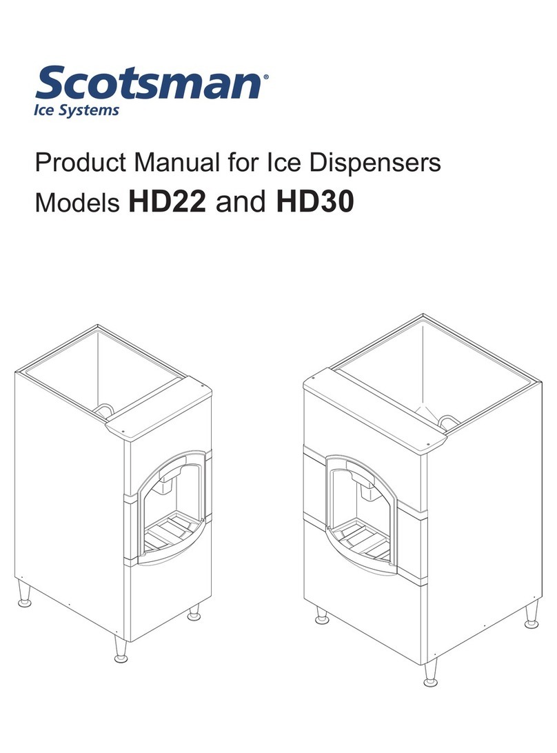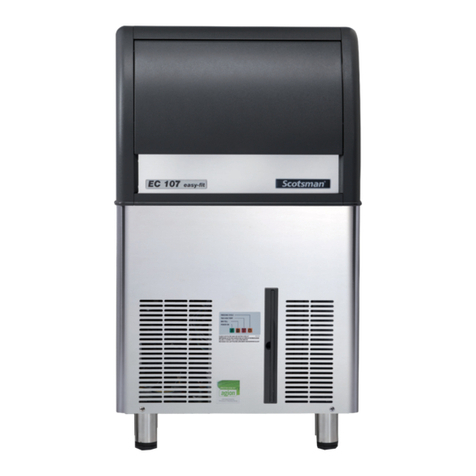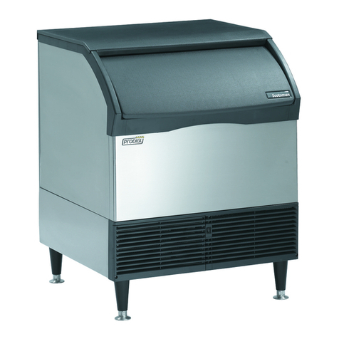
Models
The Basic version is constructed to deliver ice when the ice chute is pushed in, and it continues to vend ice as long
as the ice chute is held in.
Product Description
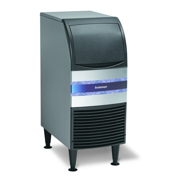
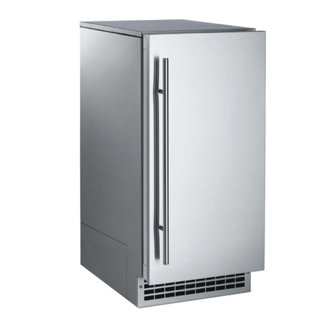
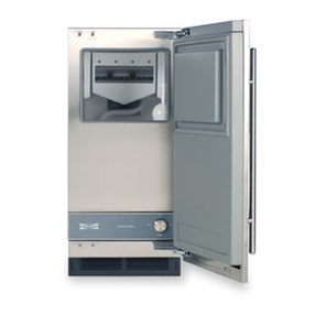
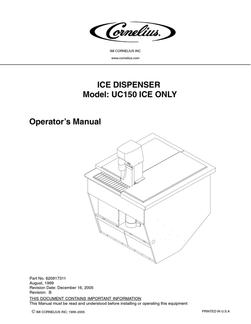
All models consist of a plastic lined, insulated hopper mounted to a metal base. The hopper contains a 15 blade
plastic dispense wheel and a stainless steel sweep arm. The top front of the hopper has a removable door to facilitate
maintenance and cleaning by the technician only of the hopper without removal of the ice machine.
The dispense wheel and sweep arm rotate when the dispense drive motor is actuated. The drive motors actuation is
controlled by the agitation timer or the vend switch. When the ice dispense chute is pushed back it moves the
actuation lever up. The actuation lever releases the chute door and pushes the vend switch arm up. When the vend
switch arm has moved a preset distance the vend switch contacts close, providing power to the dispense drive motor.
Ice is delivered to the top end of the ice chute by the dispense wheel and it slides down the chute to the container
below. The container rests on a grill, the grills openings are over the ice catch pan, and any spilled ice goes there.
The grill has a flange at the front to help contain the ice if it spills during vending. After the ice dispense chute is
released, the ice chute door closes to stop ice flow. Ice in the chute will eventually melt. Melted ice water is routed
to the drain through a hose attached to the bottom of the chute. Spilled ice is contained in an insulated ice catch pan.
Melted ice water from the ice catch pan is routed to the drain. User debris is kept away from the drain in the catch
pan by a slotted shield.
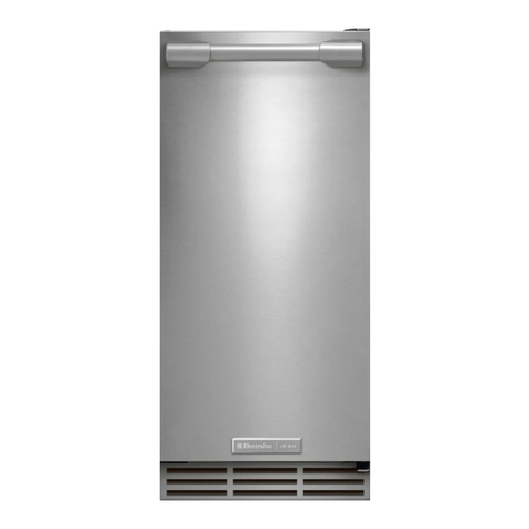
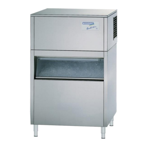
The side and front exterior panels are stainless
steel. The vending area and top panel are made
of plastic.
Unpacking
After removing the carton, check for the
loose-shipped parts packed in the storage bin.
The parts will include a carton with four legs.
Remove the leg carton and any other
loose-shipped items.
To remove the skid, place part of the carton
behind the unit and tip the unit on its back.
Remove the bolts holding the skid to the base
of the HD dispenser and separate the skid from
the unit.
Install the legs into the base of the unit, using
the holes where the skid bolts were. Turn the
leg leveler part of the legs in all the way,
adjust them later after the unit is in its final
installed position.
Move the dispenser to an upright position and
set it in the location where it will be installed.
Note where drain lines and electrical
connections will be made.
Installation - Plumbing
Drain:
4
