TO THE OWNER OR USER:
The service manual you are reading is intended to
provide you, and the maintenance or service
technician, with the information needed to install,
start up, clean, maintain and service this ice
system.
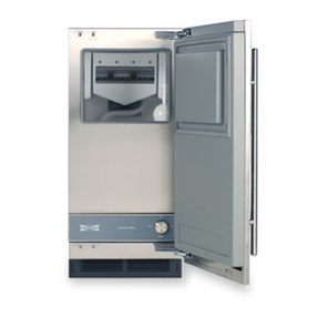
The is the freezer portion of a commercial ice
machine. It is designed to be connected to the
condensing section of a refrigeration system,
specifically a supermarket system.
Table of Contents
FOR THE INSTALLER: Specifications . . . . . . . . . . . . . . . . . . . . . . . . . . . Page 2
FOR THE INSTALLER . . . . . . . . . . . . . . . . . . . . . . . . . . . . . . . . . . . Page 3
FOR THE ELECTRICIAN . . . . . . . . . . . . . . . . . . . . . . . . . . . . . . . . . . Page 4
FOR THE PLUMBER . . . . . . . . . . . . . . . . . . . . . . . . . . . . . . . . . . . . Page 5
FOR THE INSTALLER: Final Check List . . . . . . . . . . . . . . . . . . . . . . . . . . Page 6
INITIAL START UP . . . . . . . . . . . . . . . . . . . . . . . . . . . . . . . . . . . . Page 7
COMPONENT IDENTIFICATION . . . . . . . . . . . . . . . . . . . . . . . . . . . . . . Page 8
COMPONENT DESCRIPTION: Control Box . . . . . . . . . . . . . . . . . . . . . . . . Page 9
COMPONENT DESCRIPTION: Evaporator . . . . . . . . . . . . . . . . . . . . . . . . . Page 10
ELECTRICAL SEQUENCE . . . . . . . . . . . . . . . . . . . . . . . . . . . . . . . . . Page 11
OPERATION . . . . . . . . . . . . . . . . . . . . . . . . . . . . . . . . . . . . . . . . Page 12
OPERATION: Refrigeration . . . . . . . . . . . . . . . . . . . . . . . . . . . . . . . . . Page 13
MAINTENANCE AND CLEANING . . . . . . . . . . . . . . . . . . . . . . . . . . . . . Page 14
MAINTENANCE . . . . . . . . . . . . . . . . . . . . . . . . . . . . . . . . . . . . . . . Page 15
CLEANING . . . . . . . . . . . . . . . . . . . . . . . . . . . . . . . . . . . . . . . . Page 16
SERVICE DIAGNOSIS: Condition - No Ice Being Produced . . . . . . . . . . . . . . . . Page 17
REMOVAL AND REPLACEMENT . . . . . . . . . . . . . . . . . . . . . . . . . . . . . Page 18
REMOVAL AND REPLACEMENT: Bearing And Breaker . . . . . . . . . . . . . . . . . . Page 19
REMOVAL AND REPLACEMENT . . . . . . . . . . . . . . . . . . . . . . . . . . . . . Page 20
REMOVAL AND REPLACEMENT . . . . . . . . . . . . . . . . . . . . . . . . . . . . . Page 21
REMOVAL AND REPLACEMENT: Evaporator . . . . . . . . . . . . . . . . . . . . . . . Page 22
REMOVAL AND REPLACEMENT: Gearmotor . . . . . . . . . . . . . . . . . . . . . . . Page 23
CIRCUIT BOARD TESTING . . . . . . . . . . . . . . . . . . . . . . . . . . . . . . . . Page 24
Parts lists and wiring diagrams are in the center of this manual, printed on yellow paper.
This manual was printed on recycled paper, keep
it for future reference.
Note the Warning symbol where it appears. It
marks a potential hazard.
Double System RL
March 1997
Page 1
