Page 7
Page 7
9. See data plate on the rear side of the unit
and check that local main voltage corresponds
with the voltage specified on it.
CAUTION. Incorrect voltage supplied to
the icemaker will void your parts
replacement program.
10. Remove the manufacturer’s registration
card from the inside of the User Manual and fill-
in all parts including: Model and Serial Number
taken from the data plate.
Forward the completed self-addressed
registration card to Frimont factory.
11. On ACM 55, if necessary, fit the four legs
into their seats on the machine base and adjust
them to the desired level.
C. LOCATION AND LEVELLING
WARNING.This IceCuberis designedfor
indoorinstallationonly.Extendedperiods
of operation at temperatures exceeding
the following limitations will constitute
misuseunderthetermsoftheSCOTSMAN
Manufacturer’sLimitedWarrantyresulting
in LOSS of warranty coverage.
1. Position the unit in the selected permanent
location.
Criteria for selection of location include:
a)Minimumroomtemperature10°C(50°F)
and maximum room temperature 40°C (100°F).
b) Water inlet temperatures: minimum 5°C
(40°F) and maximum 40°C (100°F).
c) Well ventilated location for air cooled
models.
d) Service access: adequate space must
beleftforallserviceconnectionsthroughtherear
of the ice maker. A minimum clearance of 15 cm
(6")mustbeleftatthesidesoftheunitforrouting
cooling air drawn into and exhausted out of the
compartment to maintain proper condensing
operation of air cooled models.
2. Level the unit in both the left to right and
front to rear directions.
D. ELECTRICAL CONNECTIONS
See data plate for current requirements to
determine wire size to be used for electrical
connections.AllSCOTSMANicemakersrequire
a solid earth wire.
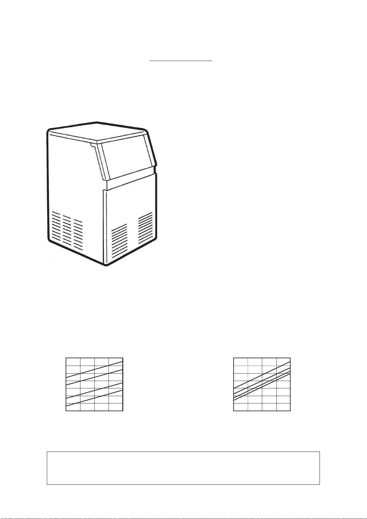
A. INTRODUCTION
This manual provides the specifications and the
step-by-stepproceduresfortheinstallation,start-
up and operation, maintenance and cleaning for
theSCOTSMANACM45andACM55icemakers.
The Electronic Cubers are quality designed,
engineered and manufactured.
Their ice making systems are thoroughly tested
providing the utmost in flexibility to fit the needs
of a particular user.
This product qualifies for the following listings:
These icemakers have been engineered to our
own rigid safety and performance standards.
NOTE
.Toretainthesafetyandperformance
built into this icemaker, it is important that
installation and maintenance be conducted
in the manner outlined in this manual.
B. UNPACKING AND INSPECTION
1. CallyourauthorizedSCOTSMANDistributor
or Dealer for proper installation.
2. Visually inspect the exterior of the packing
and skid. Any severe damage noted should be
reportedtothedeliveringcarrierandaconcealed
damageclaimformfilledinsubjettoinspectionof
the contents with the carrier’s representative
present.
3. a)Cutandremovetheplasticstripsecuring
the carton box to the skid.
b) Remove the packing nails securing the
carton box to the skid.
c)Cutopenthetopofthecartonandremove
the polystyre protection sheet.
d) Pull out the polystyre posts from the
corners and then remove the carton.
4. Remove the rear panel of the unit and
inspectforanyconcealeddamage.Notifycarrier
ofyourclaimfortheconcealeddamageassteted
in step 2 above.
5. Remove all internal support packing and
masking tape.
6. Check that refrigerant lines do not rub
againstor touchother linesor surfaces,and that
the fan blade moves freely.
7. Check that the compressor fits snugly onto
all its mounting pads.
8. Use clean damp cloth to wipe the surfaces
inside the storage bin and the outside of the
cabinet.
GENERAL INFORMATION AND INSTALLATION