TABLE OF CONTENTS – INDICE – TABLE DES MATIERES
ENGLISH
Table of Contents...............................................................................................................................................................................Page 1
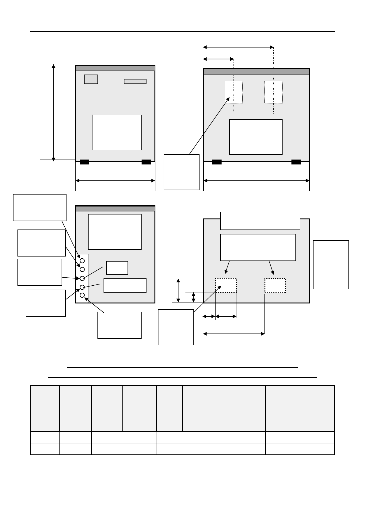
Specifications..............................................................................................................................................................................................2
Technical Specifications..............................................................................................................................................................................2
Unpacking and Inspection...........................................................................................................................................................................3
Location and Levelling ................................................................................................................................................................................3
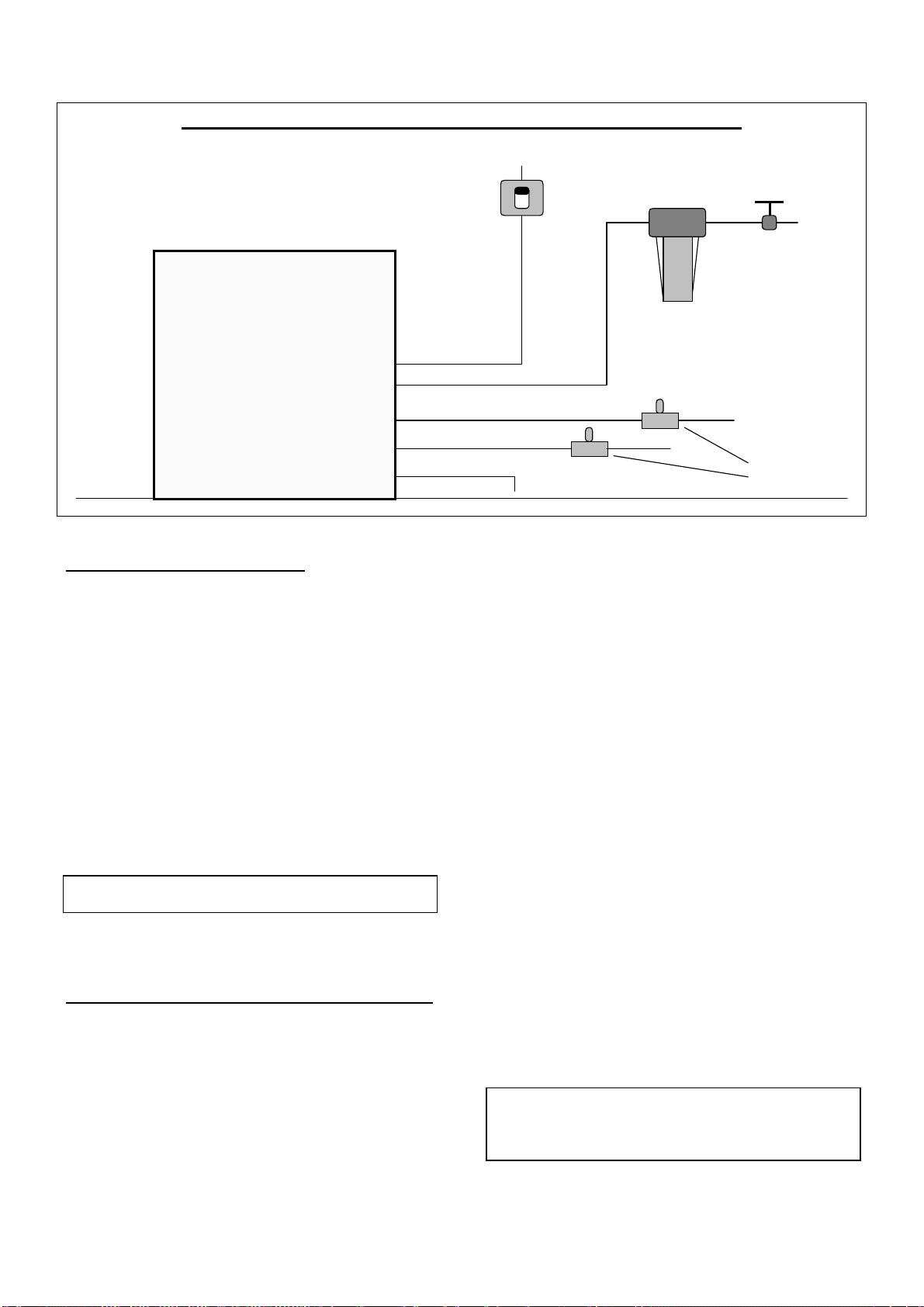
Typical Installation on Refrigerant Plant .....................................................................................................................................................4
Electrical Connections.................................................................................................................................................................................4
Water Supply and Drain Connections.........................................................................................................................................................4
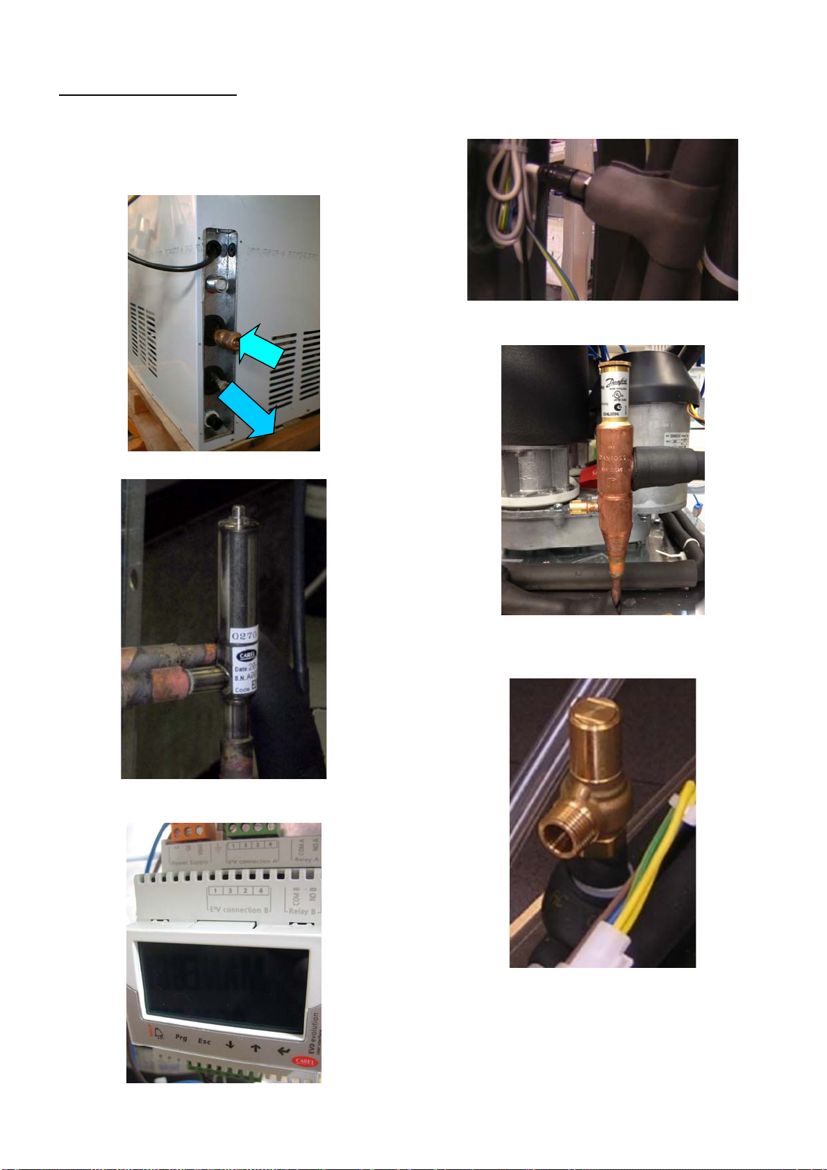
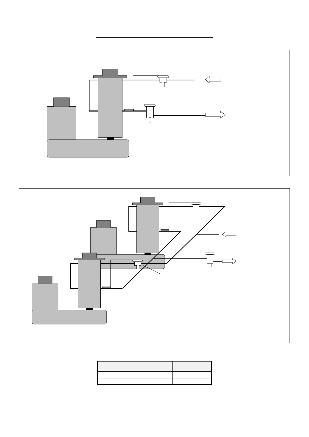
Refrigerant System .....................................................................................................................................................................................5
Refrigerant System Scheme.......................................................................................................................................................................6
Electrical System.........................................................................................................................................................................................7
PC Board and sensors................................................................................................................................................................................7
MF 59 - Driver configuration/setting procedure...........................................................................................................................................9
MF 69 – Driver configuration/setting procedure........................................................................................................................................12
Wiring Diagram MF 59..............................................................................................................................................................................46
Wiring Diagram MF 69..............................................................................................................................................................................47
ITALIANO
Indice...............................................................................................................................................................................................Pagina 1
Specifiche....................................................................................................................................................................................................2
Specifiche tecniche.....................................................................................................................................................................................2
Disimballaggio ed Ispezione .....................................................................................................................................................................17
Posizionamento e Livellamento ................................................................................................................................................................17
Istallazione Tipica su un Impianto Frigorifero ...........................................................................................................................................18
Collegamenti Elettrici ................................................................................................................................................................................18
Alimentazione Idrica e Scarico Acqua.......................................................................................................................................................18
Circuito Frigorifero.....................................................................................................................................................................................19
Schema del Circuito Frigorifero.................................................................................................................................................................20
Circuito Elettrico........................................................................................................................................................................................21
Scheda Elettronica e Sensori....................................................................................................................................................................21
MF 59 - Procedura configurazione Driver.................................................................................................................................................23
Mf 69 - Procedura configurazione Driver ..................................................................................................................................................26
Schema Elettrico MF 59............................................................................................................................................................................46
Schema Elettrico MF 69............................................................................................................................................................................47
FRANÇAIS
Table des matières.............................................................................................................................................................................Page 1
Spécifications..............................................................................................................................................................................................2
Caractéristiques techniques........................................................................................................................................................................2
Déballage et inspection.............................................................................................................................................................................32
Emplacement et mise à niveau.................................................................................................................................................................32
Installation frigorifique traditionnelle..........................................................................................................................................................33
Raccordement électrique..........................................................................................................................................................................33
Arrivée d’eau et vidange ...........................................................................................................................................................................33
Système frigorifique ..................................................................................................................................................................................34
Schéma du système frigorifique................................................................................................................................................................35
Circuit électrique .......................................................................................................................................................................................36
Carte de régulation électronique et capteurs............................................................................................................................................36
MF 59 - Procedure configuration Driver....................................................................................................................................................38
MF 69 - Procedure configuration Driver....................................................................................................................................................41
Schéma électrique MF 59.........................................................................................................................................................................46
Schéma électrrique MF 69........................................................................................................................................................................47