Screen Excellence REFERENCE User manual

1
REFERENCE
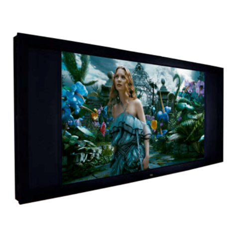
Fixed Frame Projection Screen
ASSEMBLY INSTRUCTIONS

Copyright Screen Excellence Ltd. 2017, Version 2.0 2
Caution: preliminary notice
Assembling this screen and installing it requires some professional know how. You will need 2
persons, as the screen is too heavy and bulky to be handled by a single person. You will need
to be able to evaluate a totally safe way to fix the provided brackets to the wall where it is to
be installed, and to provide it. It can be rubber, steel or plastic wall plugs, or hollow wall
anchors.
REFERENCE COMPONENTS LIST
Main frame 1. Top profile – Quantity 1 or 2 (or 3 for screens >200”)
2. Bottom profile – Quantity 1 or 2 (or 3 for screens >200”)
3. Side profiles – Quantity 2
4. Mitre angle brackets – Quantity 4
5. “Prolongator” horizontal profiles joining brackets – Quantity 2 (for screens larger
than 96”) or 4 (for screens larger than 200”)
Wall Brackets: 6. Frame Z-Brackets – Quantity 2 or 4 (for screens over 160”)
7. Wall Z-Brackets – Quantity 2 or 4 (for screens over 160”)
8. Wall snap-in bracket - Quantity 2 or 4 (for screens over 160”)
Fabric: 9. Enlightor (white) - supplied in cardboard tube
10. Black backing fabric – supplied folded
Tools: 11. Spatula – Quantity 1
13. Hex key – Quantity 2
14. Plastic foil (dust protector)– Quantity 1
Only >96” 15. Stiffening bars – Quantity 2 or 4 (for screens larger than 180”)
16. Corner support plate with bolts and nuts – Quantity 4
(optional for screens over 180”)
17. Gloves – Quantity 1 pair
You will also need the following items:
Tape measure, spirit level, sharp scissors, screws and wall plugs for fixing to wall.
The following diagram shows the parts with their corresponding item numbers.
Copyright Screen Excellence Ltd. 2017, Version 2.0 3
The following pictures shows the parts with their corresponding item numbers.
A – for screens 100” and over
B – for screens 96” and less
For screens over 200” we increase quantity of horizontal profiles to 6 and prolongators to 4.
A
B

Copyright Screen Excellence Ltd. 2017, Version 2.0 4
ASSEMBLY ADVICE
Ø Clear a space sufficiently larger than the external dimensions of the screen with access to all
sides – ideally this should be a clean, flat surface to protect the screen from damage.
Ø Carefully remove all of the components from the packaging and check them against the
components list.
Ø Locate the plastic sheet and spread it out onto your clean assembly surface.
Ø Determine the positions of the wall screws (1/4” or 6mm). The lateral position of the frame
brackets (item 6) can be changed by loosening the retaining screws and sliding the brackets to
the required position. Use wall plugs of suitable size and strength for the screen.
Ø Minimum distance of wall bracket from edge of frame should be more than 100 mm.

Copyright Screen Excellence Ltd. 2017, Version 2.0 5
ASSEMBLY ADVICE
1. Place the protective sheet on a wide, clean surface sensibly larger than the complete screen.
Place all profiles on the protective sheet. The black velvet side must be face down.
2. If you install screen with size under 100” go to page 6
3.
• Slide other ½horizontal frame (make sure all pins are in the right position)
• Tighten all screws

Copyright Screen Excellence Ltd. 2017, Version 2.0 6
4.

Copyright Screen Excellence Ltd. 2017, Version 2.0 7
For screens over 180”
5.

Copyright Screen Excellence Ltd. 2017, Version 2.0 8
6. Select the type of wall brackets between 2 solutions:
• 2 x “Z” brackets (coming as couple) and 2 x snap-in brackets: this is the standard and
simplest solution. It will apply in most cases
• 4 snap-in brackets: this is a fixing solution to install the screen in a recessed place where it
cannot be lifted to be hanged

Copyright Screen Excellence Ltd. 2017, Version 2.0 9
7. Fix 2 wall brackets (Z or snap-in) onto the wall.
If you use the “Z” brackets:
• Install frame Z brackets in position you determine
• Clip two snap-in brackets at the bottom of the frame
• Hang screen on the wall and check the final position. Adjust if needed
• Draw precisely the contour of each bottom bracket leaving them clipped in the frame groove
• Unhook the frame, unclip bottom brackets
• Place each one of the brackets in the corresponding contour line and draw a mark for each
hole
• Fix the two bottom brackets to the wall
• Hook the frame onto the wall to check position

Copyright Screen Excellence Ltd. 2017, Version 2.0 10
a. If you use the clipping snap-in brackets:
8. Remove the frame from the wall

Copyright Screen Excellence Ltd. 2017, Version 2.0 11
9. Place the frame on the protective sheet; unroll the white and black fabrics. Beware not to stain
on the white fabric. Insert the fabric into the groove of the Gripfix profile with the provided
spatula. Start by the middle of the four sides (the large sides first), and then progress towards
the corners.
Spatula Gripfix profile
It is safer to perceive the insertion position by simply inserting the tool once in the profile without the
fabric. Then remove it, place the fabric over the profile and insert it inside.

Copyright Screen Excellence Ltd. 2017, Version 2.0 12
Note:
Start from here
4 3 2 1 5 6 7 8
1) Use the spatula to insert fabric into the groove of the Gripfix from the centre to the left
2) Use the spatula to insert fabric into the groove of the Gripfix from the centre to the right
3) Place temporary the first stiffening bar just at the right of the centre
4) Use the spatula to insert fabric into the groove of the Gripfix from the centre to the left
5) Place temporary the second stiffening bar just at the left of the centre
6) Slide the first stiffening bar to the right
7) Use the spatula to insert fabric into the groove of the Gripfix from the centre to the right
a. Use the spatula to insert fabric into the groove of the Gripfix from the centre to the top
b. Do this same in the other side
c. Use the spatula to insert fabric into the groove of the Gripfix from the centre to the bottom
d. Do this same in the other side
e. If needed cut the excess fabric
10. Once the white fabric is stretched, check the evenness of the surface. The tension is not to be
excessive. In case of a problem, release locally the fabric from the profile, and insert it again.
11. Insert the Black Backing fabric the same way in the same groove as the Enlightor fabric.
Stretch it evenly.

Copyright Screen Excellence Ltd. 2017, Version 2.0 13
1) If needed cut the excess black fabric
2) Install definitely the first stiffening bar about ⅓of the total width (position usually marked)
3) Slide the pointed nut/screw next to the stiffening head and tighten them
4) Install definitely the second stiffening bar about ⅓of the total width (position usually marked)
5) Slide the pointed nut/screw next to the stiffening head and tighten them
12. Screen is fully assembled.
13. Fix the complete assembly onto a wall by hanging the two Z-brackets fixed on the screen into
the wall Z-brackets, then inserting the bottom pi-grips of the lower wall brackets into the
corresponding grooves of the screen.
If you have only snap-in brackets (when a vertical displacement is not possible), then insert the
4 wall bracket pi-grips into the screen groove by pushing it until it clips on the 4 brackets.

Copyright Screen Excellence Ltd. 2017, Version 2.0 14
Contact:
Screen Exellence Ltd.
Unit 136 Bentwaters Parks
Rendlesham
Suffolk England
IP12 2TW
www.screenexcellence.com
Telephone: +44 1394 420 220
Fax: +44 1394 420 203
twitter.com/ScreenExcel
Table of contents
Other Screen Excellence Projection Screen manuals