Stumpfl MAGNUM 210 User manual
08HW
MAGNUM 210
MAGNUM 300
MANUAL FOR ROLL UP SCREENS

2
INDEX
GENERAL INFORMATION............................................................................... 3
SAFETY INSTRUCTIONS .................................................................................. 5
MAGNUM 210 .................................................................................................. 8
Cross Section MAGNUM 210 Casing
Dimensions of the projection screen
MAGNUM 300 ................................................................................................11
Cross Section MAGNUM 300 Casing
Dimensions of the projection screen
ELECTRICAL INSTALLATION.........................................................................14
EMERGENCY LIMIT SWITCHES....................................................................16
Motor Left/ screen material back...............................................................................16-18
Motor right/ screen material front.............................................................................19-21
OPERATION LIMIT SWITCHES .....................................................................22
Motor Left/ screen material back...............................................................................22-24
Motor right/ screen material front.............................................................................25-27
ACCESSORIES..................................................................................................28
TENSIONING UNIT.........................................................................................30
DECLARATION OF CONFORMITY...............................................................31

3
ROLL-UP PROJECTION SCREEN MAGNUM
Roll-up screens MAGNUM 210 and MAGNUM 300 are permanently installed projection screens
consisting of a roll-up tube that is attached to a drive system (asynchronous tube motor) on one side
and and pivoted on the opposite.
The safety devices according to DIN 56950-1 consists of a mechanical safety brake unit and a
rotary limit switch with two adjustable emergency stop positions. Both safety devices are
connected to the winding shaft. The lateral bearing positions are connected to a two-part screen
casing made of aluminum sheet (protective casing). The projection material is rolled up on the winding
The winding tube maintains the height and the projection material is unrolled downwards.
The drive (tubular motor) can be exchanged without dismantling the projection screen if necessary.
MAGNUM projection screens can be mounted to the ceiling or to the wall via a separate bearer
construction on site.
Detail information on the roll-up screen and the serial number VAT can be found on the type plate on
the back of the screen material in the bottom left corner and at the top of the protective casing.
The screen material corresponds to a building material class in accordance with DIN 4102-1, NFPA 701
or EN 13501-1and is in line with the limit values for waviness according to ÖNORM A 2115.
corresponding product data sheet. www.AVstump.com/projectionmaterials
GENERAL INFORMATION

4
QUALITY AND SAFETY
The roll-up projection screen is in line with the applicable European guidelines and standards
(incomplete excerpt):
Directive 2006/42/EC on Machinery
Low Voltage Directive 2014/35/EU
Electromagnetic Compatibility Directive 2014/30/EU
DIN 19045-2 Projection of still pictures and motion pictures - Part 2: Screens
DIN 56950-1 Entertainment Technology - Machinery Installations - Part 1: Safety requirements and
inspection
DIN 56950-4 Entertainment Technology - Machinery Installations - Part 4: Safety requirements for
serially manufactured projection screens
DECLARATION OF CONFORMITY
According to the EU-Machinery Directive (2006/42/EG) the roll up screen MAGNUM is a machine.
WARRANTY
The roll up screen MAGNUM may only be used as a projection screen.
No persons are allowed to stay in the operation area. For all damages to persons and property
which occur from inappropriate use the warranty will be invalid and the manufacturer cannot be
held responsible. The intended use also includes the observance of all instructions and information
contained in this operating manual.
regulations with media control panel operation on page 14.
The general terms and conditions are available at www.AVstump.com/generalterms
UNAUTHORIZED MODIFICATIONS
warranty claims.
CHANGING THE IMAGE HEIGHT - WARRANTY OF FLATNESS
and for maintenance work.
5
SAFETY INSTRUCTIONS
cases of transport damage is provided on the info sheet IMPORTANT INFORMATION.
Before assembly make sure that the wall or the ceiling is able to carry the load. Choose the screws/
attachment material in accordance with the weight of the projection screen and the condition of wall
or ceiling. The permissible loads on walls, fastenings, connecting and transmission elements must not
exceed the maximum holding force and catch torque.
radiators, ventilation and air condition systems. To ensure safe and trouble-free operation make sure
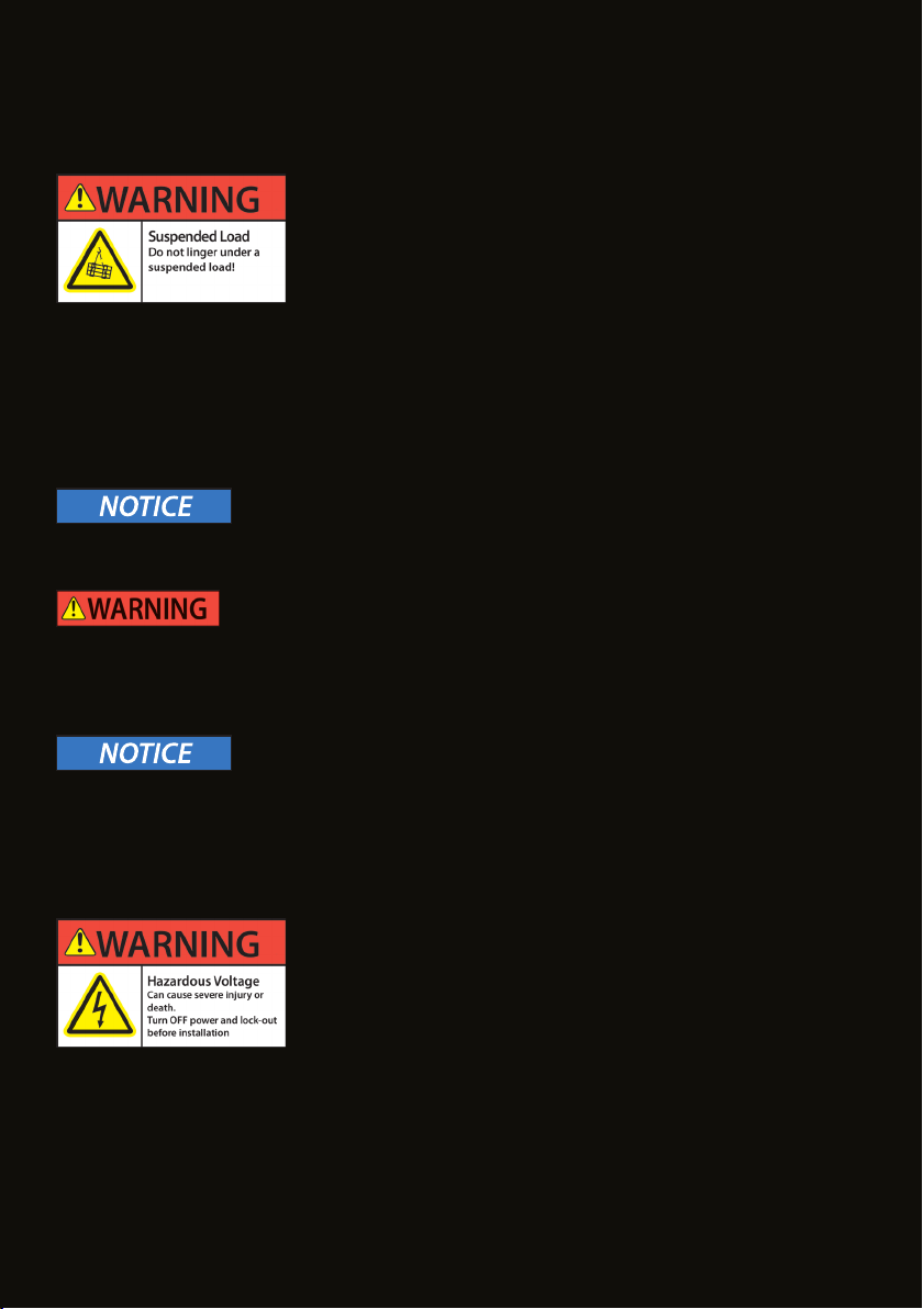
The roll-up screen must be secured during transport and assembly
in accordance with the total weight. During lifting work, no person
must remain in the danger zone below the suspended load
The total weight is displayed on the roll-up screen type plate or on the packaging. For mounting use
hoisting equipment which is approved for the weight of the roll up screen. Make sure the roll-up
screen is transported and mounted horizontally and torsion-free to prevent the safety brake from
engaging. Do not put additional mechanical load on the lightweight aluminium casing.
MECHANICAL MOUNTING
TRANSPORT – MOUNTING
The electrical installation is to be performed by a trained electrician
from a licensed expert company only. Please hand over this manual
and the connection directions that are supplied separately with every
motor or switch or control unit to the executing expert.
The electrical installation must only be carried out in a voltage-free and secured against
Prior to the installation check the isolation of the connecting cable and the cable feedthrough at the
casing for damage. Check that there is no ohmic continuity between the connecting cable and the roll-
up screen casing so that any danger by indirect contact is excluded. Control units must not be installed
in the operating area of the roll-up screen.
ELECTRICAL INSTALLATION

6
FIRST-TIME OPERATION
are signs of danger or danger situations roll-up screen operation must be stopped immediately.
During the test run the operator must always have full and direct sight of the roll-up screen.
in the roll-up screen casing during transport or assembly and that the screen material can unwind
OPERATION
The operator must undergo a training regarding the technical construction and operating principle to
ensure safe operation. The operator must have basic knowledge of the industry safety standards.
Take appropriate measures to ensure that the roll up screen cannot be operated by untrained
persons or activated unintentionally.
The projection screen must only be operated in a well lit environment so as to recognize any danger
situations that might occur. During operation the operator must always have full and direct sight of the
roll-up screen so as to be able to stop it immediately when a danger situation occurs.
Supervision by adults is required when putting the roll-up screen into operation.
During operation the movement range and the immediate area of the roll-up screen must be
Before winding up the screen check the bottom bar and the screen material for damage and remove
any possible obstacles within the movement range. No additional loads must be attached to / or lifted
by the bottom bar.
In the case of recognizable damage to the roll-up screen it must immediately be taken out of service. It
can only be put back into service after being repaired and checked/cleared for use by an expert.
MAINTENANCE TIPS - CLEANING
During work at the roll-up screen make sure that it cannot be started accidentally.
Protect the screen material from soiling. If necessary clean it with a slightly damp and soft cloth.
Do not use any aggressive cleaning agents, such as acetone, terpentine, cellulose thinners or ethyl
alcohol or similar substances.
7
MAINTENANCE
Drives, bearings and other rotating parts of the roll-up screen are permanently lubricated and are
maintenance-free. The roll-up screen must be protected from soiling.
Maintenance and repair work must only be carried out be authorized experts.
SAFETY INSPECTION
MAGNUM roll-up screens must undergo annual safety inspection.
In case of visible damage or unusual noises during the operation the roll-up screen must
immediately be taken out of service. It must only be returned to service upon successful repair
and inspection/clearance for use by an expert.
national legal regulations (installing person/company, TÜV, consulting engineer).
The inspection must be performed in accordance with DGUV 17 (BGV C1) and the regulations
according to DIN 56950-1 Appendix A and the applicable national regulations.
We recommend performing the following measures:
•
• Perform a test run
• Visual inspection of winding behavior
• Check for operating noises at the bearing locations
• Check operating limit switches (stop point of upper and lower limit switches)
• Check function of the emergency limit switch (by mechanical triggering or triggering by previous
adjustment of the operating limit switches)
• Visual inspection of the connection between bottom bar and screen material
• Check electrical control unit and safety installations
• Check “dead man’s control” for screens with more than 5 m width or height
DISASSEMBLY
For disassembly the same safety instructions apply as listed for TRANSPORT - MOUNTING on page 5.
DISPOSAL
At the end of its lifetime this product must not be disposed of with normal household waste but needs
to be taken to a collection site for recycling.
Disassembly of a MAGNUM roll-up screen takes a few steps only and by separate disposal of the waste
you can make an important contribution towards environmental protection.
In separated form the materials can be recycled.
Casing components and bottom bar are made of aluminum and the lateral bracktes are made of steel.
For the projection screen material refer to the type plate.
The motor drive is to be disposed of at a collection center for electric devices.
Contact your local disposal company for the address of a collection center.

8
26,5154
34
207
207
29
40
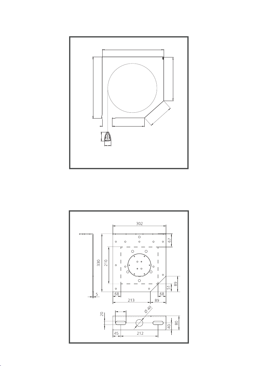
CROSS SECTION MAGNUM 210 CASING
UNIVERSAL MOUNTING BRACKET
FOR CEILING MOUNTING
9
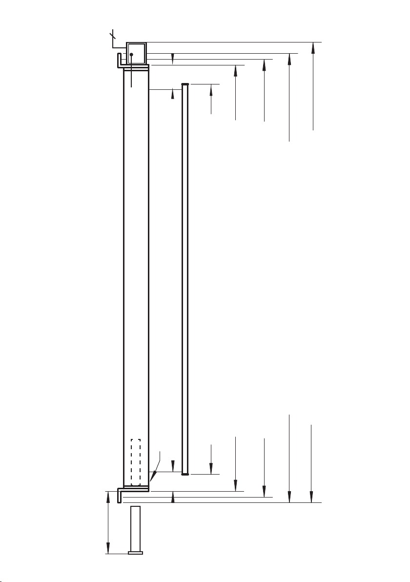
MAGNUM 210
Dimensions of the projection screen
* For servicing and adjusment of the rotary limit switch and safety catch the casing must be accessible
at least from the front and the bottom.
8x 0,75²
~61mm ~61mm
Fabric
length of bottom bar = fabric width +26mm
MAGNUM 210 casing
casing length = fabric width +123mm
hole center distance = fabric width +159mm
overall length mounting brackets = fabric width +195
overall length: +/- 5mm
overall length = fabric width +360
connecting cable : length 5m, gray
Casing for rotary limit
switch with safety catch*
Service area for motor
exchange min. 800mm
Stop position adjustment

10
170
197,5
MAGNUM 210
fabric front
Dimensions of the projection screen
* For servicing and adjusment of the rotary limit switch and safety catch the casing must be accessible
at least from the front and the bottom.
8x 0,75²
~61mm ~61mm
Fabric
length of bottom bar = fabric width +26mm
MAGNUM 210 casing
casing length = fabric width +123mm
hole center distance = fabric width +159mm
overall length mounting brackets = fabric width +195
overall length: +/- 5mm
overall length = fabric width +360
Casing for rotary limit
switch with safety catch*
Stop position adjustment
connecting cable : length 5m, gray
Service area for motor
exchange min. 800mm
11
300
214
300
125
157
49
40
29
60
CROSS SECTION MAGNUM 300 CASING
MOUNTING BRACKET MAGNUM 300
FOR CEILING MOUNTING

12
8x 0,75²
215
210
MAGNUM 300
Dimensions of the projection screen
* For servicing and adjusment of the rotary limit switch and safety catch the casing must be accessible at least from the front and the
bottom.
~75mm ~72mm
Fabric
length of bottom bar = fabric width +26mm
MAGNUM 300 casing
casing length = fabric width +146mm
hole center distance = fabric width +216mm
overall length = fabric width +440mm
overall length: +/- 5mm
overall length mounting brackets = fabric width +296mm
connecting cable : length 5m, black
Casing for rotary limit
switch with safety catch*
Service area for motor
exchange min. 800mm
Stop position adjustment

13
* For servicing and adjusment of the rotary limit switch and safety catch the casing
must be accessible at least from the front and the bottom.
8x 0,75²
~72mm ~75mm
Fabric
length of bottom bar = fabric width +26mm
MAGNUM 300 casing
casing length = fabric width +146mm
hole center distance = fabric width +216mm
overall length = fabric width +440mm
overall length: +/- 5mm
overall length mounting brackets = fabric width +296mm
Casing for rotary limit
switch with safety catch*
Stop position adjustment
connecting cable : length 5m, gray
MAGNUM 300
fabric front
Dimensions of the projection screen

14
ELECTRICAL INSTALLATION
Work at mains voltage (230 V) must only be performed by a licensed
electrical company. Please hand over this manual and the connection
directions that are supplied separately with every motor or switch
or control unit to the executing expert.To get further important
instructions refer to chapter SAFETY INSTRUCTIONS on page 4:
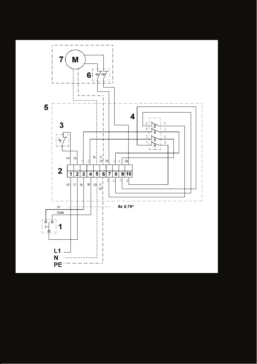
INDIVIDUAL CONTROL - 230 V
(See circuit diagram)
Incorrect control of the tube motor results in electrical overload on the limit switches and may change
the set stop positions. In extreme cases permanently welded contacts of the the limit switches can
occur. This causes the motor to be permanently activated and the projection screen to be damaged.
IN ORDER TO AVOID AN ELECTRICAL OVERLOAD OF THE LIMIT SWITCHES IN THE TUBE MOTOR,
THE WIRING AND THE CONTROL COMMANDS ‚ MUST COMPLY WITH THE FOLLOWING
REGULATIONS:
1. Do not run two or more motors in parallel from one output.
A separate contact must be available for every drive and running direction.
2. switches and controls must not allow simultaneous UP-and DOWM commands.
Simultaneous up and down commands cause a short-circuit of the operating capacitor.
For that reason only electrically or mechanically locked single switches (no light switches) must
be used.
3. The CHANGEOVER-DELAY BETWEEN UP AND DOWN COMMAND MUST BE 500ms at least.
Switching periods under 0,5s results in extremely high currents, which may result in the limit switches
being welded together and therefore the projection screen being damaged.
OPERATION VIA A MEDIA CONTROL SYSTEM (DRY CONTACT)
Any damage to the motor and consequential damage caused by non-integration of a motor control
unit are excluded from the warranty.
Motor control unit-> See chapter “Accessories”
ELECTRIC SUPPLY
230VAC 50Hz. Line circuit breaker 10 A. Motor cable 4x0,75mm²
Tubular motors are not suitable for continuous operation and have a duty cycle of 3-4 minutes. If the
roll-up screen is operated for a longer period of time, a thermal protection relay switches the motor
15
ELS - UP (6-5)
OLS - UP (1-3)
OLS - DOWN (2-4)
ELS - DOWN (7-8)
3- SAFETY CONTACT - SAFETY BRAKE
WIRING SCHEME
GEAR LIMIT SWITCH WITH 4 CONTACTS
16
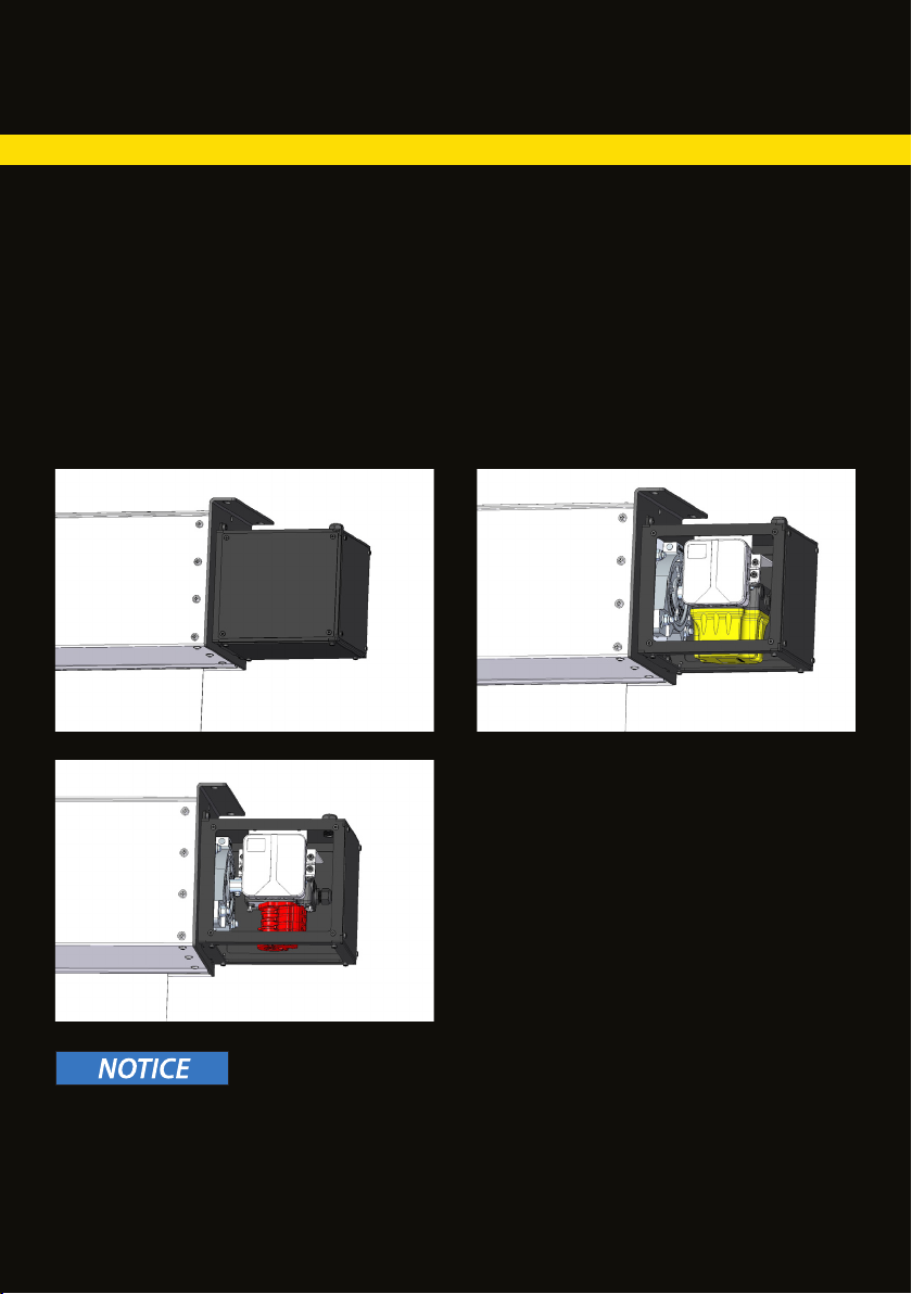
1 2
3
EMERGENCY LIMIT SWITCH
MOTOR LEFT/ SCREEN MATERIAL BACK
The movement range of a MAGNUM 210 and 300 roll-up screen is additionally limited by a gear-type
limit switch with emergency limit switches for both stop positions.
The emergency limit switches and operating limit switches are factory-set according to the ordered
image size.
If the installation situation requires a reduction of the movement range, the emergency limit switches
must be adjusted before setting the operating limit switches.
see chapter Adjustment of stop positions (page 22-24)
Do a test run.
1-2 Start by removing the front and lower casing
cover (2,5mm hexagonal Allen key).
2-3In order to get access to the cam unit, (red)
remove the cover (yellow) of the gear limit
switch. (Phillips or slot screwdriver).
LOSS OF WARRANTY
The projection screen is factory set according the dimensions orderedand the gear limit switch is
sealed.
Damage and consequential damage due to incorrect limit switch adjustment are not covered by
warranty.

17
4
ADJUSTING THE UPPER EMERGENCY LIMIT SWITCH
In order to ensure safe operation of the roll-up screen the stop point of the upper emergency limit
screen is pulled into the screen casing and consequently falls down.
The bottom bar falling down may cause serious injuries to persons within the danger area below the
projection screen.
4 The stop point for the upper emergency limit switch is set by means of the set screw at the top
switching cam (red).
Turning the screw clockwise moves the stop point UP.
CAUTION: There is a danger that the bottom bar of the projection screen is pulled into the
screen casing and consequently falls down.
Turning the screw counter-clockwise moves the stop point DOWN.
Proceed by doing a test run.
Then set the upper operating limit switch. (See chapter operating limit switch on page 23)
EMERGENCY LIMIT SWITCH
MOTOR LEFT/ SCREEN MATERIAL BACK

18
5
EMERGENCY LIMIT SWITCH
MOTOR LEFT/ SCREEN MATERIAL BACK
Turning the screw clockwise moves the stop point UP.
Turning the screw counter-clockwise moves the stop point DOWN.
The screen material falling down may cause severe injuries to persons within the danger area below
the projection screen.
ADJUSTING THE LOWER EMERGENCY LIMIT SWITCH
5The stop point for the lower emergency limit switch is set by means of the set screw at the lower
switching cam (red).
Proceed by doing a test run.
Then set the lower operating limit switch. (See chapter operating limit switch on page 24)

19
1 2
3
MOTOR RIGHT/ SCREEN MATERIAL FRONT
EMERGENCY LIMIT SWITCH
The movement range of a MAGNUM 210 and 300 roll-up screen is additionally limited by a gear-type
limit switch with emergency limit switches for both stop positions.
The emergency limit switches and operating limit switches are factory-set according to the ordered
image size.
If the installation situation requires a reduction of the movement range, the emergency limit switches
must be adjusted before setting the operating limit switch.
see chapter operating limit switches (page 25-27)
Do a test run.
1-2 Start by removing the front and lower casing
cover (2,5mm hexagonal Allen key).
2-3In order to get access to the cam unit,
(green) remove the cover (yellow) of the gear
limit switch. (Phillips or slot screwdriver).
LOSS OF WARRANTY
The projection screen is factory set according the dimensions orderedand the gear limit switch is
sealed.
Damage and consequential damage due to incorrect limit switch adjustment are not covered by
warranty.

20
4
MOTOR RIGHT/ SCREEN MATERIAL FRONT
4The stop point for the upper emergency limit switch is set by means of the set screw at the top
switching cam (red).
Turning the screw clockwise moves the stop point DOWN.
Turning the screw counter-clockwise moves the stop point UP.
(CAUTION: There is a danger that the bottom bar of the projection screen is pulled into the
screen casing and consequently falls down.)
Proceed by doing a test run.
Then set the lower operating limit switch. (See chapter operating limit switch on page 24)
EMERGENCY LIMIT SWITCH
ADJUSTING THE UPPER EMERGENCY LIMIT SWITCH
In order to ensure safe operation of the roll-up screen the stop point of the upper emergency limit
screen is pulled into the screen casing and consequently falls down.
The bottom bar falling down may cause serious injuries to persons within the danger area below the
projection screen.
This manual suits for next models
1
Table of contents
Other Stumpfl Projection Screen manuals


Popular Projection Screen manuals by other brands

Rehau
Rehau Relazzo R24600 Screen technical information

SCREENLINE
SCREENLINE COPERNICO BIFORMAT instructions

DecisionVision
DecisionVision DV-15 Operator's manual

AVstumpfl
AVstumpfl MONOBLOX 32 instructions

Screen Int
Screen Int FLAT ELASTIC VELVET CURVED installation manual

Stewart Filmscreen
Stewart Filmscreen RP-1013 owner's manual


Avtek
Avtek FOLD user manual

Elite Screens
Elite Screens EDGE FREE Aeon Series user guide

Elite Prime Vision
Elite Prime Vision EPVMAX series user guide

Draper
Draper Signature E Series Installation & operating instructions

Topcon
Topcon CC-100 Series Quick manual

Elite Screens
Elite Screens MicroFlip Screen user guide