Screen Int SI-H XL 500 User manual

1
MOTORIZED PROJECTOR LIFT
MOD. SI-H XL 500 (version OCT-2021)
INSTALLATION MANUAL
Thank you for purchasing the new SI-H XL 500 Projector Lift.
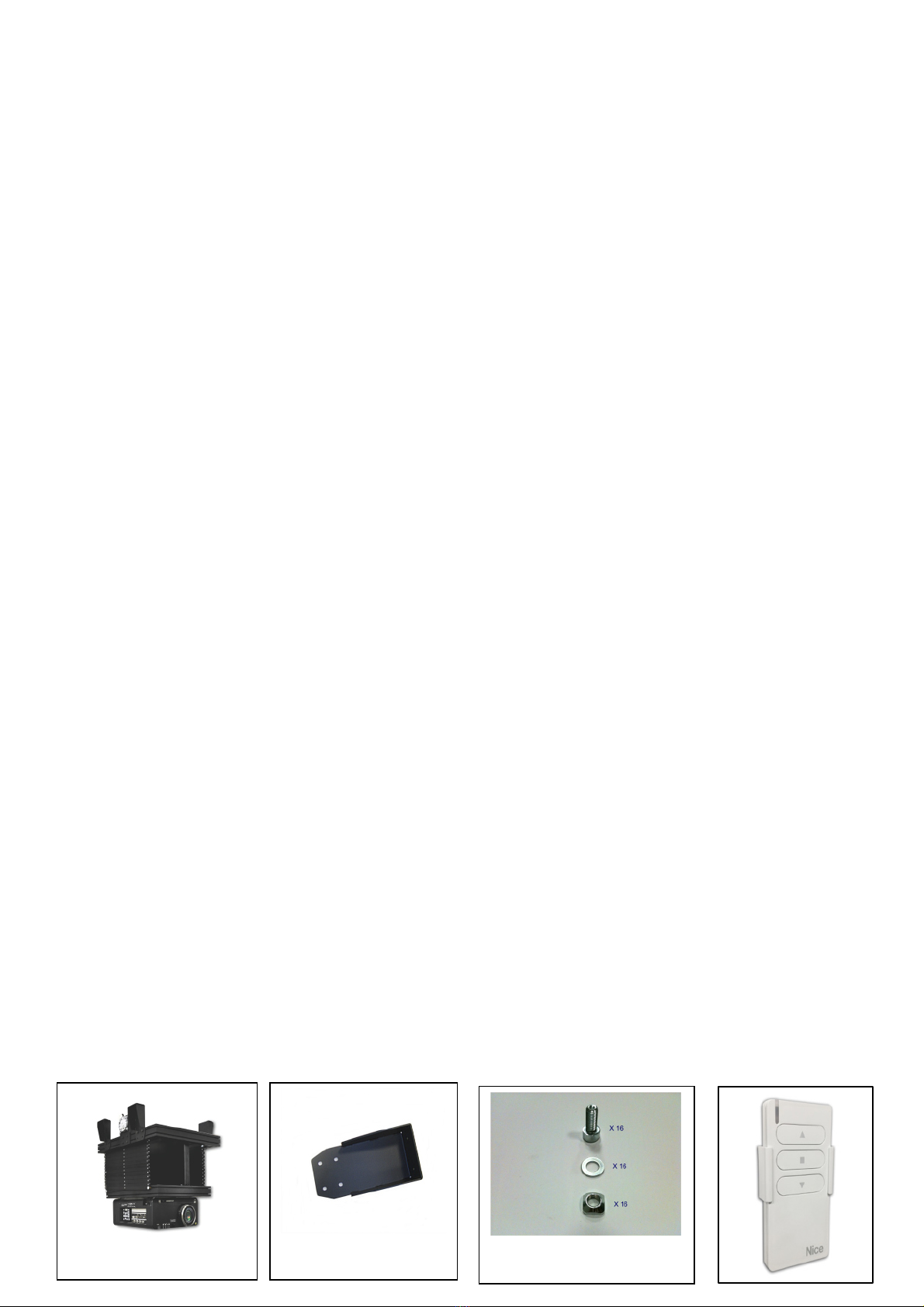
The SI-H XL 500 is supplied with a set of components and accessories that make it suitable for installation for
the majority of standard AV applications, but note must be made of the restrictions that apply to the weight
capability of this unit and not exceeded.
BEFORE INSTALLING THE LIFT, PLEASE READ THE FOLLOWING INSTRUCTIONS CAREFULLY. Please, always
keep these instructions so that anyone can read them when needed.
THE MANUFACTURER DOES NOT TAKE RESPONSIBILITY FOR ANY DAMAGE TO PROPERTY OR PERSONAL
INJURY IF THE PROJECTOR LIFT IS USED OUTSIDE OF RECOMMENDED SPECIFICATIONS OR IN CASE OF
INCORRECT INSTALLATION.
Before installing the projector lift, please read the following instructions carefully:
•The projector lift must be used INDOORS ONLY.
INSTALLATION OF SI-H XL 500 PROJECTOR LIFT HAS TO BE CARRIED OUT FROM
QUALIFIED PERSONNEL ONLY.
•IT IS FORBIDDEN TO STAY UNDER THE LIFT AND WITHIN A RANGE OF 3 MT. FROM THE
LIFT.
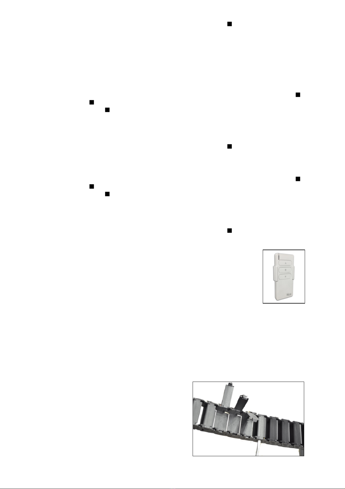
•NEVER CONNECT MORE THAN ONE MOTOR TO THE SAME SWITCHER. USE THE
SUPPLIED REMOTE CONTROL ONLY.
•IN CASE OF MAINTENANCE, UNPLUG THE POWER SUPPLY.
•Please conrm that your projected image width will t your screen from your proposed
mounting location prior to installation.
•Incorrect use of the lift, including exceeding the maximum lifting weight, will be
dangerous. The manufacturer does not take responsibility for any damage o property or
personal injury if the lift is used outside of recommended specications.
•Incorrect use of the projector lift, including exceeding the maximum lifting weight of 95
kg., would be dangerous and invalidates the warranty.
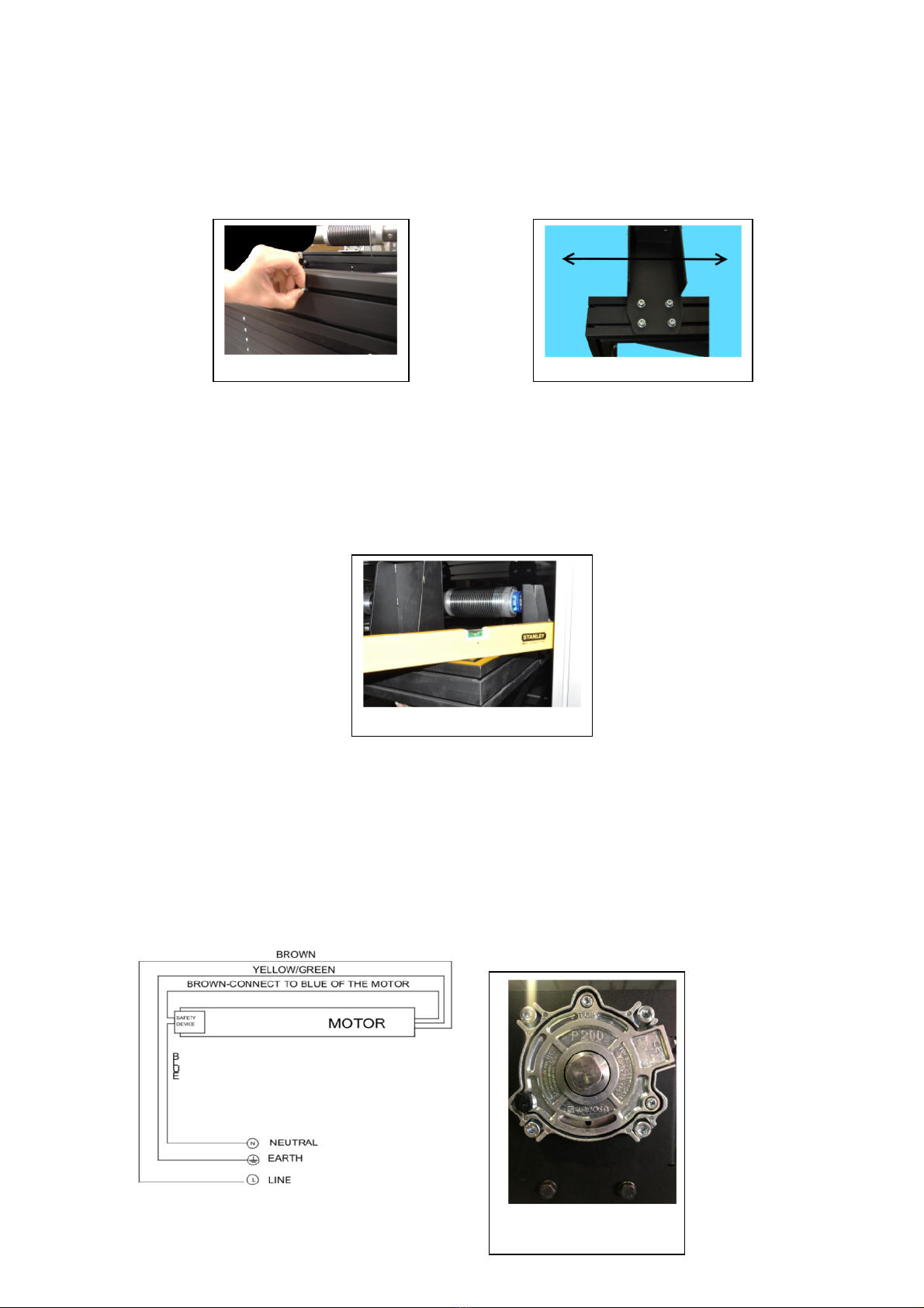
•This product uses a 230V AC Motor. DO NOT attempt to service the motor. Incorrect
servicing could lead to risk of electric shock.
•For any repairing, please contact directly the dealer you purchased the unit from.
•DO NOT try to disassemble the lift or to paint the structure, as these operations will
invalidate the warranty.
•Half-yearly and yearly the screen winch system has to be checked. Please see check
register at page 8 of this document.
•In addition to manufacturer inspection guidelines, we recommend you check your
countries own legal obligations for checking and testing of lifting equipment.
The manufacturer and his agents do not take responsibility for any damage to property
or personal injury if the winch is installed/used outside of recommended
specications.
This product uses a 230 V AC motor. DO NOT attempt to carry out repairs to
the motor, there are no user serviceable parts.
Incorrect servicing could lead to risk of electric shock. In the event of a
fault, please contact the dealer /supplier you purchased the lift from.
Warranty is 24 months Return To Base.
The projector lift SI-H XL 500 is certied.

2
WARRANTY CONDITIONS
This projector lift is guaranteed 2 years from the purchase date for manufacturing defects and
5 years on motor defects.
Responsibility is limited to repairing or substitution of the defected components and without any
other charge at our expense.
Warranty is ofcially voided if the lift has been dismantled or it is returned with collision damage
or defective due to incorrect installation. Repairs must be carried out by an Approved ScreenInt
Certied Engineer.
Warranty is ofcially voided if (all the following cases are including but not limited):
1) defects not due to deciencies in the material or workmanship;
2) amendments, alterations, repairs or disassembling of the Product not previously
authorized in writing by Screenint;
3) installation, use or maintenance of the Product not in compliance with Screenint ‘s
instructions as set forth in this Installation Manual and/or in any other technical documentation
supplied together with the Product;
4) bad and/or improper and/or not in compliance installation, maintenance, negligence,
improper use;
5) use of non-original spare parts or not authorized in writing by Screenint;
6) normal wear and tear;
7) the motor is removed / dismantled;
8) the projector lift has been damaged in transit;
9) the instructions regarding the electrical connections have not been followed;
10) the products have to be installed following the electric regulations (CEI) and the other
local specic laws;
11) in the installation are used electric interfaces that does not allow the correct time lapse
between up and down operation (complete cut down of electric power on both phases for one
second)
12) electrical accessories have been used that are incompatible with the lift motor causing
damage to its internal components;
13) the sticker regarding the serial number of the product has been altered, deleted, removed
or tampered.
SUPPLIED EQUIPMENT LIST
When you open the packaging, please CHECK that it contains ALL the components below listed. In case one
or more components are missed, please refer to the dealer you purchased the product from.
A) 1 MECHANIC PROJECTOR LIFT SI-H XL 500
B) 4 METAL BRACKETS FOR CEILING MOUNTING
C) 16 SOCKET HEAD SCREWS 8X20
D) 16 M8 WASHERS
E) 16 M8 CROWNED NUTS
F) RF REMOTE CONTROL
G) INSTALLATION MANUAL
BC D E
A
F

3
CEILING MOUNTING
- In order to mount the four metal brackets shown on Fig. “B” above on the upper aluminium frame of the
SI-H XL 500, please use screws, washers and crowned nuts mentioned on “C, D, E” of the supplied
equipment list; put inside the groove of the aluminium frame the crowned nut as shown on Fig. 1A;
connect the ceiling bracket to the prole by the socket head screws and the crowned nuts, move the
ceiling bracket along the prole in order to position it where needed (Fig. 1B); now rmly tighten the
screws of the four brackets.
- Note: the four ceiling mounting brackets can be mounted in two different ways on the upper frame of
the lift:
1- Brackets mounted towards outside – Fig. 8A – page 7
2- Brackets mounted towards inside – Fig. 8B – page 7
- Once the four brackets have been mounted on the upper frame of the lift, mount the lift to the ceiling
using wall plugs and screws (NOT supplied) specic for the type of material to drill. During the installation
pay attention that the lift is perfectly levelled both on the width and on the depth. (See Fig. 2).
ELECTRIC CONNECTION
- The motor has the possibility to be controlled via the supplied handheld RF remote control or via wired
low voltage contact closures.
- The motor has a six-core power cable. NEVER CONNECT THE MAINS TO THE WIRES WHITE, WHITE-
BLACK, WHITE-ORANGE.
- Once the lift is mounted to the ceiling, connect the wires brown, blue and yellow/green to the mains,
following the scheme shown in Fig. 3A;
- The lift is supplied with a safety mechanism (Fig. 3B) with a double security system: rst - this is a
mechanic safety system that prevents the steel cable to unroll when the speed has reached 50 rpm, second
– this is an electrical security system that disconnect the electrical connection of the motor if the force
driven on the steel cable, caused by the falling
down, is more than 503 Nm.
Fig. 1B
Fig. 1A
Fig. 2
Fig. 3A
Fig. 3B

4
FIXING THE PROJECTOR TO THE LIFT
- Roll down the SI-H XL 500 by pushing ▼button on the remote control (Fig. 7A) in order to lower the lift
till the lower end-stop (SERVICE mode), preset in the factory at 2,5 mt. ca. In case you wish to modify
the lower end-stop (SERVICE mode), please refer to instructions at page 4 and 5.
In order to x the projector under the lift, position the splines of the three proles of the lower lift frame,
to match the anchoring points on the projector (Fig. 4A).
Unloose the four screws as shown on Fig. 4B and position the three proles where needed (Fig. 4C).
Once you have aligned the splines of the proles with the anchoring points on the projector, tighten the
screws and the bolts of the proles following a cross scheme.
Repeat this step until all the screws on the three proles will be very well tightened.
Insert the screws for mounting the projector in the milling of the proles (milling depth 10 mm) and
tighten the screws to the anchoring points of your projector.
ADJUSTMENT OF PITCHING AND ROLLING OF THE PROJECTOR
Projectors have not a regular distribution of the weight on their surface but tent to have unbalancing caused
by the lamp, by the optical system and so on.
Unbalancing could lead to either a right and left rolling or a pitching of the lower lift frame - projector.
The SI-H XL 500 have been developed to solve these problems and allow to adjust the lift in order to get a
perfect balance of the entire lifting system.
In order to adjust PITCHING, please move the motor along the prole where the motor itself is xed, by
loosing the screws as shown on Fig. 5A and 5B and move the motor left or right until the lower frame will be
perfectly balanced (Fig. 5C).
PLEASE, PROCEED WITH THIS STEP, AFTER HAVING LAYED THE PROJECTOR MOUNTED ON THE
FRAME ON A SUPPORT SURFACE, IN ORDER TO LIGHTEN THE MOTOR FROM THE WEIGHT.
Now loose the screws on Fig. 5D and using a rubber hammer, move the prole of Fig. 5E, left or right in
order that the steel cables are perpendicular both to the upper part and to the lower part of the lift (see Fig.
5F). At the end of the adjustment, tighten the screws rmly (Fig. 5D).
Fig. 4A
Fig. 5A Fig. 5B Fig. 5C
Fig. 4B Fig. 4C

5
In order to adjust ROLLING, please tighten or unloose the nuts that act on the tension of the steel cables.
(Fig. 6A)
ADJUSTMENT OF THE END STOPS
PLEASE READ CAREFULLY
The SI-H XL 500 motorized lift is supplied with a remote control that allows to set three positions:
1- CLOSED LIFT: preset by the factory, in closed upper position. WARNING: in case the installer
needs to modify this end-stop, it is ONLY allowed to lower the upper end-stop position. Do not try
to raise the upper end-stop because this will cause severe damages to the product and
this operation will invalidate the warranty.
2- PROJECTION MODE: intermediate stop position, NOT preset by the factory.
3- SERVICE MODE: lower end-stop position, preset by the factory at 2,5 mt. circa.
How to modify the end-stops:
A- SETTING OF THE LOWER END STOP (SERVICE MODE)
- Lower down the lift till half stroke, pressing the remote control button ▼and stop it with button .
- Press the button (for 5 secs) till the motor swivels 2 times.
- Press again the button (for 5 sec) till the motor swivels 4 times.
- Press the button ▼(for 5 sec) till the motor swivels 2 times.
- Press and hold the buttons ▼or ▲in order to the reach the desired position of the lift. Warning: during
this programming operation you have to keep the buttons ▼or ▲pressed in order to reach the
desired position.
Fig. 6A
Fig. 5D Fig. 5E Fig. 5F

6
- Once this position is reached, in order to memorize it press the button (for 5 sec) till the motor
swivels 3 times.
B- SETTING OF THE UPPER END STOP
WARNING: in case the installer needs to modify this end-stop, it is ONLY allowed to lower the upper end-
stop position. Do not try to raise the upper end-stop because this will cause severe damages to
the product and this operation will invalidate the warranty.
- Lower down the lift till half stroke, pressing the remote control button ▼and stop it with button .
- Press the button (for 5 secs) till the motor swivels 2 times.
- Press again the button (for 5 sec) till the motor swivels 4 times.
- Press the button ▲(for 5 sec) till the motor swivels 2 times.
- Press and hold the buttons ▼or ▲in order to the reach the desired position of the lift. Warning: during
this programming operation you have to keep the buttons ▼or ▲pressed in order to reach the
desired position.
- Once this position is reached, in order to memorize it press the button (for 5 sec) till the motor
swivels 3 times.
C- SETTING OF THE INTERMEDIATE STOP (PROJECTION MODE)
- Lower down the lift till half stroke, pressing the remote control button ▼and stop it with button .
- Press the button (for 5 secs) till the motor swivels 2 times.
- Press again the button (for 5 sec) till the motor swivels 4 times.
- Press simultaneously the buttons ▲+▼(for 5 sec) till the motor swivels 2 times.
- Press and hold the buttons ▼or ▲in order to the reach the desired position of the lift. Warning: during
this programming operation you have to keep the buttons ▼or ▲pressed in order to reach the
desired position.
- Once this position is reached, in order to memorize it press the button (for 5 sec) till the motor
swivels 3 times.
D- USE OF THE REMOTE CONTROL
- Press the button ▼in order to reach the lower-end stop (SERVICE mode).
- Press the button ▲in order to reach the upper-end stop.
- Press simultaneously the buttons ▲+▼in order to reach the intermediate
stop (PROJECTION mode).
E – CONNECTION OF LOW VOLTAGE CONTACTS TO REACH THE DIFFERENT END-STOPS.
- Close the connection, for at least 1 second, between the white-black and white-orange wires in
order to reach the LOWER end stop (SERVICE mode).
- Close the connection, for at least 1 second, between the white-black and white wires in order to
reach the UPPER end stop.
- Close the connection, for at least 1 second, simultaneously between the white-black, white-orange
and white wires in order to reach the INTERMEDIATE stop (PROJECTION mode).
The SI-H XL 500 projector lift includes a CABLE MANAGEMENT
SYSTEM.
In order to t in the power and signal cables of the projector
Move the lift in the lower end stop position (SERVICE MODE),
and open the small doors, as shown in Fig. 7B.
Fig. 7B
Fig. 7A

7
TECHNICAL DETAILS
POWER SUPPLY 230 V 50HZ
CONSUMPTION 360 W
TORQUE 80 Nm
MOTOR SPEED 12 rpm
ROLL UP/DOWN SPEED 17 sec./metre
TERMICAL STOP after 4 minutes of operation
NET WEIGHT LIFT SI-H XL 500 kg. 78
MAXIMUM LOAD OF THE PROJECTOR kg. 95
DIMENSIONS SI-H XL 500 CLOSED 790x716x890 (WxHxD in mm.)
DIMENSIONS SI-H XL 500 OPENED 790x5716x890 (WxHxD in mm.)
Fig. 8
B
A

8
PROJECTOR LIFT SI-HXL300/SI -HXL500-CHECKREGISTER
In addition to manufacturer inspection guidelines, we recommendyou check your countries own legal obligations
for checking and testing of lifting equipment.
PROJECTOR LIFT SI-HXL300/SI-HXL500 PURCHASE DATE:
HALF-YEARLY CHECK
DATE
YEARLY CHECK
DATE
CHECKRESULT
(POSITIVE -NEGATIVE) NOTES
HALF-YEARLYCHECK Checkifrolling upand rolling downis workingproperly, without frictions or decelerations.
Checkthat if youcan hear the ticking noiseof the safety brake ispresent.
YEARLYCHECK Checksteel cables covered by blackPVC– nosteel wires have to be visible outside the black PVCscabbard.
Checkof the ceiling fixingbrackets of the projector lift
Checkthat the upper endstopisset properly, sothat it is avoidedthat the motor remainsin traction before reaching the
upper end stop.
Avoidthat when the lift reaches the upperendstop,it hits an obstacle(ex. upperframe structure of the lift itself or the
ceiling tile holder hitsthe false ceiling).
Checkthat boltsonthe bottom endsof the steel cables are tightly fixed.
Checkthat the bolts ofthe anchoring pointsof the projector are tightly fixed.
Checkif rolling upand rolling downis workingproperly, without frictions or decelerations.
Checkthat if youcan hear the ticking noiseof the safety brake ispresent.
Table of contents
Other Screen Int Projector Accessories manuals
Popular Projector Accessories manuals by other brands

InFocus
InFocus SP-LAMP-080 Replacement instructions

Extron electronics
Extron electronics PMP Series Specifications

Linksys
Linksys WPG12 - Wireless Presentation Player Specifications

Elite Screens
Elite Screens VMAX113XWS Specifications

Navitar
Navitar 373MCZ125 installation instructions

Duronic
Duronic FPS manual