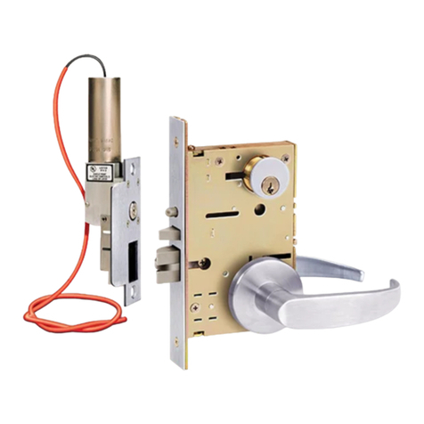
SDC ZY7500 Series User manual

P:\INST INSTRUCTIONS\ELECTRIFIED LOCKSETS\INST-ZY7500 REV B 05-22 Page 1
Any suggestions or comments to this instruction or
product are welcome. Please contact us through
our website or email engineer@sdcsecurity.com
A. Door Preparation:
1. Measure desired height from finished floor, mark a horizontal line on door and door edge.
2. Align template on edge of door with applicable horizontal at height line. Check the chart for drilling trim
holes on template and mark only holes for lock function being installed.
3. Mortise door edge according to measurements on installation template and drill proper holes for trim.
4. Recess for face plate, the dimension is:
L 8-1/32" x W 1-5/16" x D 7/32".
Height
line
C
L of lever
7/32"
ZY7500 SERIES
SOLENOID FRAME ACTUATOR
CONTROLLED MORTISE LOCKSET
of cylinder
of lockcase
of lever rose shown
Vertical centerline
C
Installation
template
C
L
C
L
C
L
L of door edge
INSTALLATION INSTRUCTIONS
SECURITY DOOR CONTROLS ■ WWW.SDCSECURITY.COM
[t] 800.413.8783 ■ 805.494.0622 ■ E-mail: [email protected] ■ 801 Avenida Acaso, Camarillo, CA 93012 ■ PO Box 3670, Camarillo, CA 93011
Note:
Rose door prep shown as example.
Escutcheon door prep would differ.

P:\INST INSTRUCTIONS\ELECTRIFIED LOCKSETS\INST-ZY7500 REV B 05-22 Page 2
B. Install Lockcase
Make sure the lock hand matches the door hand, use the following diagram to determine the hand of door.
1. Change latchbolt handing
If the hand of the latchbolt doesn’t match the door hand, remove the fixing screw and pull the latchbolt out from
lock case. Turn the latchbolt 180 ° to change the handling. Position latchbolt back, into case and fasten it.
Instructions for changing lock hand:
Remove
screw
Pull out and
turn
2. Change hand of lock
For RH and RHRB, the catch screw will be on the lock case side. For LH and LHRB, the catch screw will be on the
lock cover side.
SECURITY DOOR CONTROLS ■ WWW.SDCSECURITY.COM
[t] 800.413.8783 ■ 805.494.0622 ■ E-mail: [email protected] ■ 801 Avenida Acaso, Camarillo, CA 93012 ■ PO Box 3670, Camarillo, CA 93011
LH
Left Hand
LHRB
Left Hand
Reverse Bevel
INSIDE OF DOOR
OUTSIDE OF DOOR
RH
Right Hand
RHRB
Right Hand
Reverse Bevel
INSIDE OF DOOR
OUTSIDE OF DOOR

P:\INST INSTRUCTIONS\ELECTRIFIED LOCKSETS\INST-ZY7500 REV B 05-22 Page 3
SECURITY DOOR CONTROLS ■ WWW.SDCSECURITY.COM
[t] 800.413.8783 ■ 805.494.0622 ■ E-mail: [email protected] ■ 801 Avenida Acaso, Camarillo, CA 93012 ■ PO Box 3670, Camarillo, CA 93011
1. Insert spindles as shown
D. Install lever trim
1. Place the reversible spring cage onto the ferrules with arrow pointing in direction of lever rotation.
2. Install outside trim with mounting posts through door and position lever onto the spindle.
3. Install inside spring cage onto the spindle with the arrow pointing in the direction of inside lever rotation.
4. Install inside mounting plate onto spindle. Tighten with provided screw.
5. Cap inside rose over mounting plate.
C. Install Spindles
Reversible spring
cage
Ferrule
Mounting
post
Into Mounting post
B. Install Lockcase (Continued)
6. Screw inside lever into position and tighten lever collar with supplied spanner wrench.
Spanner wrench
Spanner wrench
3. Connect wires as shown on the lock cover diagram (Or refer to page 6 of
instructions.)
4. Insert lockcase into mortise cut-out and fasten screws to door.

P:\INST INSTRUCTIONS\ELECTRIFIED LOCKSETS\INST-ZY7500 REV B 05-22 Page 4
SECURITY DOOR CONTROLS ■ WWW.SDCSECURITY.COM
[t] 800.413.8783 ■ 805.494.0622 ■ E-mail: [email protected] ■ 801 Avenida Acaso, Camarillo, CA 93012 ■ PO Box 3670, Camarillo, CA 93011
E. Install for 07 lever trim
F. Install Cylinder and Armor Face Plate
Spanner
wrench
FACE PLATE
Collar
Spring
Outside Lever Assy
Spindle
Mounting
Plate
Rose
Inside Lever
Spring Cage
Spring
1. Place the spring, collar and then reversible spring cage onto the outside lever assembly with arrows pointing in
direction of lever rotation. Insert spindle into hub of lock case.
2. Install outside lever assembly with mounting posts through door and position lever assembly onto the spindle.
3. Install inside spring cage onto the spindle with the arrows pointing in the direction of inside lever rotation.
4. Install inside mounting plate over spindle and onto the mounting posts of outside assembly. Tighten with provided
screws.
5. Cap inside rose over mounting plate and insert second spring.
6. Screw inside lever into position and tighten lever collar with the supplied spanner wrench.
1. Screw cylinder into threaded hole of the lock case.
2. Tighten the set screw against cylinder(s) by turning clockwise as shown.
3. Install face plate onto the lock case and fasten with supplied screw.
Use standard straight
cam (863G), or
equivalent (863M).

P:\INST INSTRUCTIONS\ELECTRIFIED LOCKSETS\INST-ZY7500 REV B 05-22 Page 5
For the frame portion (electric actuator) read these instructions carefully.
To insure a neat and easy installation of the electric actuator into the frame back box when making long wire runs, the heavier gauge
wire can be terminated in a junction box above the door. At this point a smaller gauge wire cable may be run from the junction box to
the frame electrical black box. This provides for easier insertion of the electric actuator.
For proper operation the voltage as indicated on the lock solenoid must be at the lock location with the load on.
1. The wiring assignments are shown on page 6
as well as on the electric actuator. The lock is supplied with
6" wire leads and will require a min. 10" leads from the conduit.
2. Insert wires into the jamb carefully so they do not interfere with
proper positioning of the lock in the cut-out.
3. Insert lock and secure with screws provided.
4. While the actuator is energized, verify that the appropriate function
is working properly. The actuator is factory set for a 1/8” door clearance.
If the clearance between the door and jamb is more or less than 1/8”
then the following adjustment must be made (refer to Fig. 2).
A. Loosen the Allen screw in the plunger.
B. Remove plunger head.
C. Turn each adjustment screw equally in desired direction.
Counter-clockwise for wide gaps – clockwise for narrow gaps.
IMPORTANT:
ADJUSTMENT SCREWS MUST BE TURNED EQUALLY TO OPERATE FREELY.
D. Replace plunger head and test lock. Lever should lock
when actuator is energized.
5. If ordered with Latch position sensor, then adjustment is factory set for 1/8” door
clearance and is adjustable for wide and narrow door gaps. If adjustment is required
please follow steps A, B & C.
Refer to Fig. 2.
A. Loosen the two screws on the side of the dust box.
B. Move the switch assembly forward or back to desired position.
Example: For 3/16” door gap move the switch assembly forward 1/16”.
C. Tighten screws.
Strike Plate Dimensions
For Metal Frames: 4-7/8” x 1-1/4” x .0937" Standard ANSI
For narrow metal frames: 8-1/2” x 1-1/4” x 1/8”
ID Requirements
Standard Actuator: 12" x 2-1/2” x 1-3/4”
Narrow Backset Actuator: 12" x 2-1/2” x 1-1/4”
Fail Safe: Continuous duty – locked when energized
UL Listed: Electrically controlled single point locks or latches
SECURITY DOOR CONTROLS ■ WWW.SDCSECURITY.COM
[t] 800.413.8783 ■ 805.494.0622 ■ E-mail: [email protected] ■ 801 Avenida Acaso, Camarillo, CA 93012 ■ PO Box 3670, Camarillo, CA 93011
FRAME ACTUATOR
INSTALLATION GUIDE
Electric Actuator.
Solenoid points down.
FIG. 1
FIG. 2
DOOR
ELECTRICAL
BACK BOX
FRAME
LATCH STATUS
ADJUSTMENT
MOVE FORWARD FOR
WIDE DOOR GAP
ADJUSTABLE
SCREWS MOVE
OUT FOR WIDE
DOOR GAP
ACTUATOR
PLUNGER
HEAD

P:\INST INSTRUCTIONS\ELECTRIFIED LOCKSETS\INST-ZY7500 REV B 05-22 Page 6
SECURITY DOOR CONTROLS ■ WWW.SDCSECURITY.COM
[t] 800.413.8783 ■ 805.494.0622 ■ E-mail: [email protected] ■ 801 Avenida Acaso, Camarillo, CA 93012 ■ PO Box 3670, Camarillo, CA 93011
Important Note:
Because of design, field OHM tests of AC solenoids may
produce erratic readings and cannot be used to determine
the solenoids condition.
RED
WHT
BLU/BLK
YEL/BLK
ORG/BLK Indicates Door Opened
Common
Indicates Door Latched
BLU/BLK
YEL
ORG Indicates door unlocked
Common
Indicates door secure
Optional (S) Latch & Locked Status
SPDT 5 Amps @ 125VAC
Optional (L) Latch Status Sensor
SPDT 5 Amps @ 125VAC
Voltage and current rating stamped on solenoid
Ground screw is provided on 115 VAC locks
Standard wiring
Optional: SC-10 - 10ft Cable, Input Power Socket Connector
+
-
COM
N/C
N/O
Optional: SC-10-5 - 10ft Cable, Input Power & Monitoring Socket Connector
RESISTANCE IN
OHMS 5%
+
-
AMPS
24VDC
54.5
.44
24VAC
13.6
.45
115VAC
293
.20
VOLTAGE
+
-
RED
BLK
+
-
RED
WHT
COM
N/C
N/O
BLK
BRN
GRN
Common
Indicates Door Opened
Indicates Door Latched
Indicates Door Unlocked
Indicates Door Secure
Common
Optional (L) Latch Status Sensor
SPDT 5 Amps @ 125VAC
Optional (S) Latch & Locked Status
SPDT 5 Amps @ 125VAC

The 7500 Series is a Electric Power to Lock Unit which is failsafe in that it unlocks when power is removed. The most commonly used function is the
7550 model which is locked when energized on the outside and free on the inside egress. Models 7530 & 7560 are locked on both sides.
(1) Power on controller plunger does not
throw.
1A Insufficient voltage 1A Check voltage with a meter at the lock
farthest from source with all locks
energized. Meter should indicate the
same voltage stamped on the solenoid
body. If voltage is low, either too small of
a wire gauge was used or there is too
great of a load on the line.
1B Binding caused by uneven plunger
adjustment.
1B Adjust plunger evenly (Refer to Fig 2).
1C Electric portion wired wrong. 1C Review wiring diagram on side of lock &
instruction sheet.
(2) Latch bolt throws only part way, lock
chatters or buzzes.
2A Door alignment does not permit
latch bolt to enter strike
2A Proper alignment must be achieved by
correctly hanging the door in a properly
installed frame. Modifying the lock and
strike will not remedy the problem.
Modification will void UL listing and
warranty.
(3) Inside lever is locked, outside is free. 3A Incorrect handing 3A Remove mortise lock and reverse hand.
(4) Latch position switch does not signal
properly.
4A Adjustment is off. 4A Adjust sensor. See Step 5 of instructions.
SOLUTIONSCAUSEPROBLEM
TROUBLE SHOOTING HiTower® 7500 SERIES
FUNCTIONS
7530
Mortise is locked while energized
and is unlocked by a remote
switch or by means of a key from
either side.
Suggested: communicating locks,
man trap
7550
Mortise is locked while energized
and is unlocked by remote switch
or by means of an outside key or
by rotating the inside lever.
Suggested: stair tower doors,
classrooms, laboratories, offices,
man trap.
7560
Mortise is locked and is unlocked
when energized by a remote
switch or by means of a key from
either side.
Suggested: communicating locks,
man trap
7570
Mortise is locked is unlocked
when energized by remote switch
or by means of an outside key or
by rotating the inside lever.
Suggested: stair tower doors,
classrooms, laboratories, offices,
man trap.
SECURITY DOOR CONTROLS ■ WWW.SDCSECURITY.COM
[t] 800.413.8783 ■ 805.494.0622 ■ E-mail: [email protected] ■ 801 Avenida Acaso, Camarillo, CA 93012 ■ PO Box 3670, Camarillo, CA 93011
P:\INST INSTRUCTIONS\ELECTRIFIED LOCKSETS\INST-ZY7500 REV B 05-22 Page 7
Table of contents
Other SDC Controllers manuals
Popular Controllers manuals by other brands

Danfoss
Danfoss 101N0715 operating instructions

Interactive Technologies
Interactive Technologies CueServer 2 user manual

Munters
Munters TRIO User and installation manual

Zennio
Zennio FANinBOX 110V 1CH Technical documentation

Samson
Samson 3374 Mounting and operating instructions

Eltek
Eltek Smartpack S user guide