Sea Recovery SRC Aqua Matic 450-1 User manual

Aqua Matic
Model 450-1800
Owner’s Manual
Rev. A - 29 October 2008
Manual PN B651120002A
Sea Recovery Corp.
19610 S. Rancho Way
Rancho Dominguez, Ca 90220
www.searecovery.com • sales@searecovery.com
SRC Aqua Matic 450-1
SRC Aqua Matic 700-1
SRC Aqua Matic 900-1
SRC Aqua Matic 900-2
SRC Aqua Matic 1400-2
SRC Aqua Matic 1800-2
FOR SYSTEM V3.00-MAY 2007


Aqua Matic 450-1800 Rev. A
TABLE OF CONTENTS
SECTION CONTENTS PAGE
Table of Contents i - iv
Copyright v
Terms and Conditions v
Patent Notification v
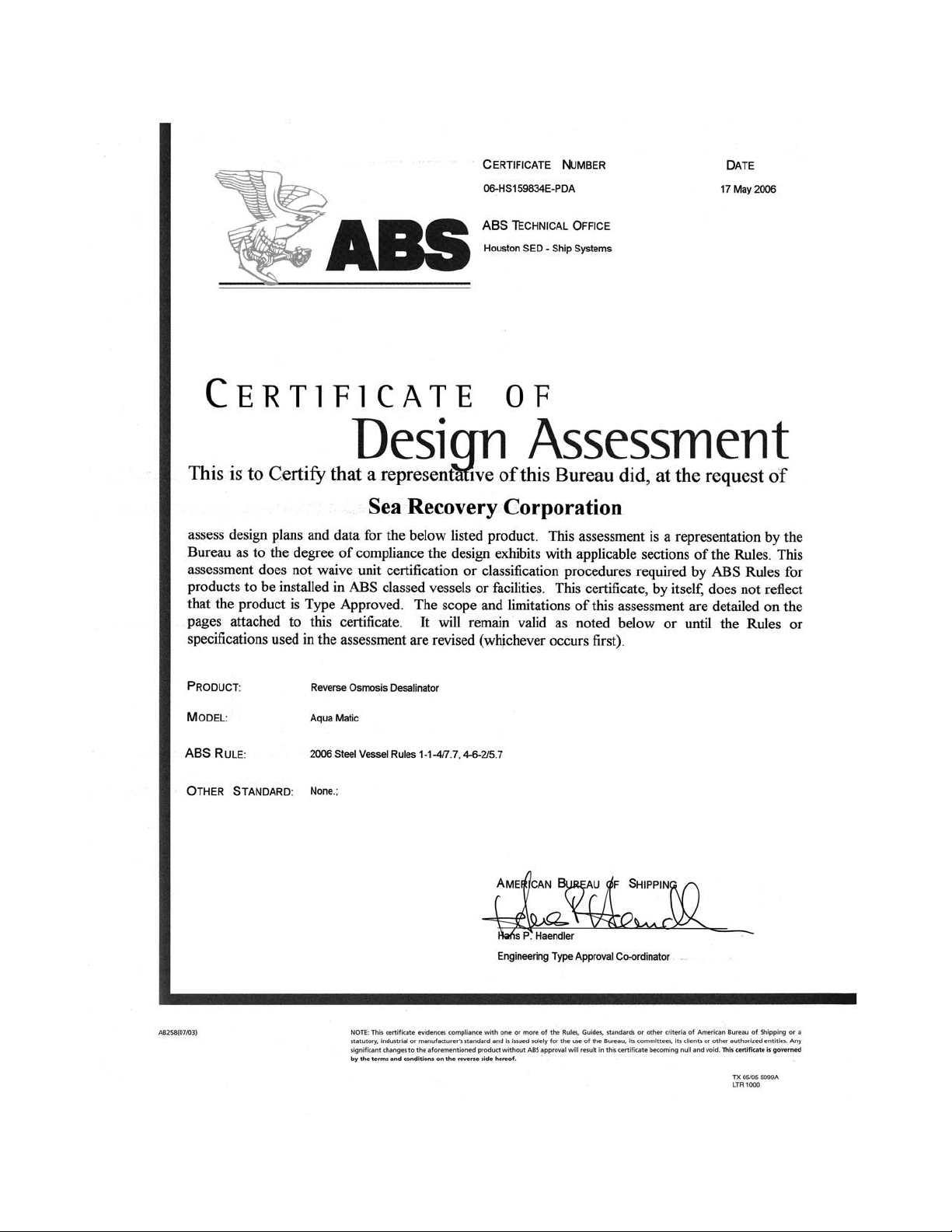
Approvals vi - ix
American Bureau of Shipping Type Acceptance vi - vii
Federal Communications Commission Compliance viii
Conformité Européne CE Compliance viii
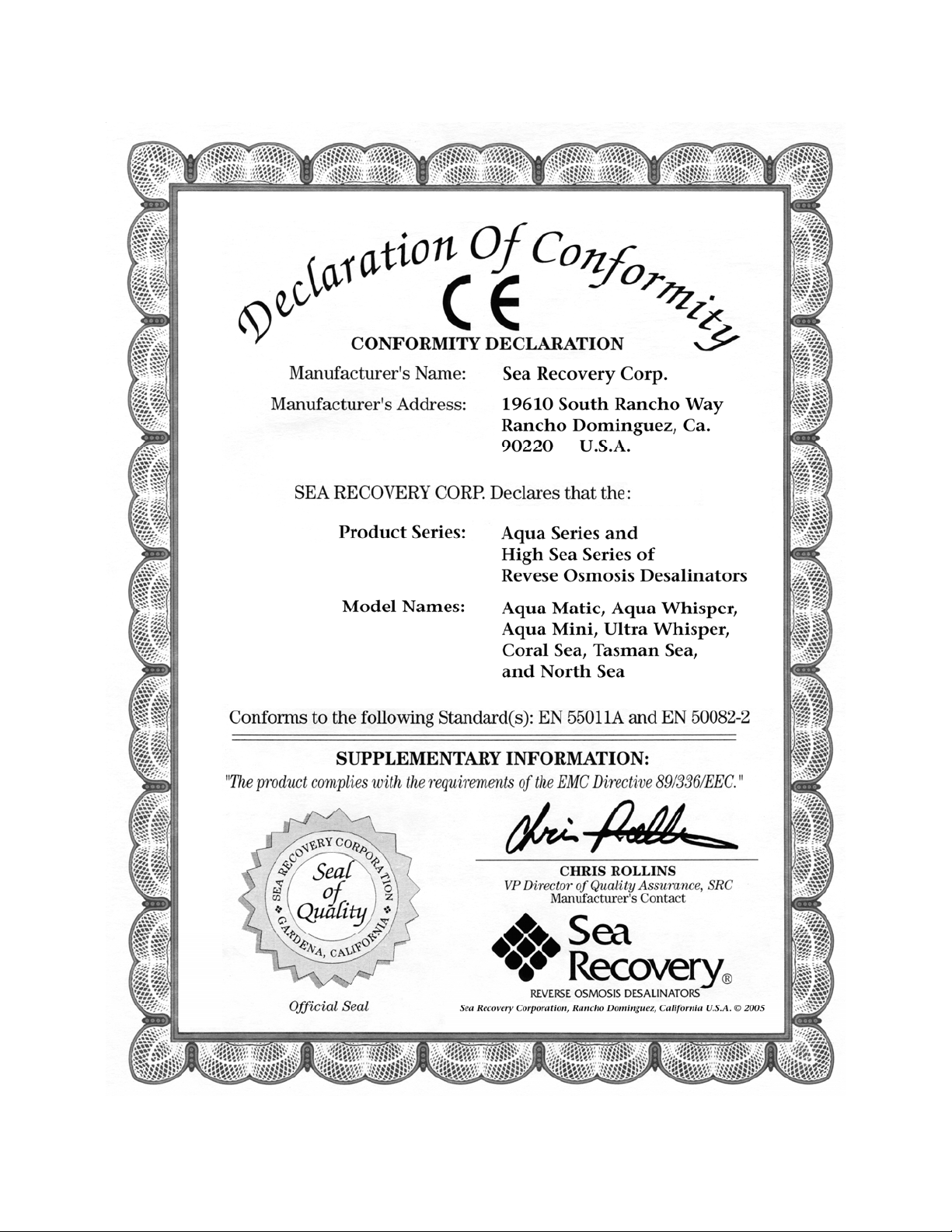
CE Declaration of Conformity ix
Limited Warranty x
Warranty Registration Form xi - xii
System Identification Information Form xiii
Preface xiv
System Information Screen xv
Specifications xvi - xviii
1 Section 1
INTRODUCTION, COMPONENT IDENTIFICATION & EXPLANATION 1 - 20
Sea Recovery’s Approach to Desalination 3
Osmosis & Reverse Osmosis 3
Spiral Wound Reverse Osmosis Membrane Element 3
Anatomy of a Reverse Osmosis Membrane Element 4
Introduction to the System & Component Descriptions 5
Component Identification Piping and Interconnect Diagram (P&ID) 6
Component Location Illustration, Aqua Matic Compact Style 7
Component Location Illustration, Aqua Matic Modular Style 8
Component Descriptions 9 - 19
Helpful Terms 20
2 Section 2
PRE-INSTALLATION R.O. MEMBRANE CARE, SYSTEM INSTALLATION, and LAND INSTALLATION
Installation of the Aqua Matic and Membrane Care prior to installation 1 - 56
System Storage and Installation Precautions and Information 3
Storage Prior to Uncrating 3
Reverse Osmosis Membrane Element Susceptibility to Chemical Attack 3
Installation Competency 3
Installation Cautions 3
Special Considerations 4 - 5
Installation Cautions 4
Connection Line Cautions 4
Accessibility Cautions 4
Electrical Power Requirements 5
Distance Between Components 5
Tools Required For Installation 5
Components Supplied by Installer or Owner 5 - 6
Visual Packing List Aqua Matic Compact Style 7
Visual Packing List Aqua Matic Modular Style 8
Visual Packing List Aqua Matic Optional Accessories 9
Dimensions Aqua Matic Compact Style 10
Dimensions Aqua Matic Modular Style 11
Dimensions Aqua Matic Modular Optional Accessories 12
Piping and Interconnect Diagrams 13 - 17
i

Aqua Matic 450-1800 Rev. A
Prefiltration Interconnect Diagrams 18 - 19
Explanation of Pressure Transducers 20
Prefiltration Configurations 21 - 25
Reverse Osmosis Membrane Element Note 25
Installation of and specific to Aqua Matic Compact Style 26 - 37
Placement and securing the main system frame 27
Component mounting 27 - 33
Tubing and Hose precautions 34
Interconnecting components with supplied hose 35 - 36
Customer supplied fresh water tank high and low level switches, and alarm 36 - 37
Remote Control installation 37
Electrical connection notes and cautions 37
Installation of and specific to Aqua Matic Modular Style 38 - 53
Component mounting 38 - 47
Tubing and Hose precautions 48
Interconnecting components with supplied hose 49 - 51
Customer supplied fresh water tank high and low level switches, and alarm 51 - 52
Remote Control installation 52
Electrical connection notes and cautions 53
Land Installation Illustrations 54 - 55
3 Section 3
AQUA MATIC FEATURES SET-UP, PROGRAMMING THE SYSTEM, CALIBRATIONS, and FUNCTION
TESTS
Features Set Up of the Aqua Matic System (user programming) 1 - 12
Features Set-Up and Programming the Control Logic explanation 3
Programming the Aqua Matic computer logic 4 - 10
Screen Contrast 4
U.S. Standard or metric standard measurements 4
Diversion valve set point 4
Model setup 5
Fresh water flush option setup 6 - 7
Differential Pressure Transducer 8
Salinity Calibration 8
Brine Water and Product Water Flow Meter Calibration 8
Detect Remote 9
Function Tests of Electric Components 10
• Booster Pump Electric Motor
• High Pressure Pump Electric Motor
• Diversion Valve energize solenoid
• Fresh Water Flush Valve
• Back Pressure Regulator Electric Motor Actuator
• U.V. Sterilizer Ballast and Lamp
System Information Screen 11
4 Section 4
NEW SYSTEM COMMISSIONING
Commissioning of a New Aqua Matic System 1 - 16
System Commissioning Notes 3
Installation Check 3
Reverse Osmosis Membrane Element notes 3 - 4
ii

Aqua Matic 450-1800 Rev. A
Commissioning and Start-Up Procedure of a New System 4 - 14
New System Initial Readings Log 15 - 16
5 Section 5
SYSTEM OPERATION
Operating the Aqua Matic 1 - 18
Notes Regarding the Automated Operational Sequence 3
Reverse Osmosis Membrane Element Warning 4
Automatic Mode WITHOUT the Fresh Water Flush option 5 - 7
Automatic Mode WITH the Fresh Water Flush option 8 - 10
Manual Mode 11 - 14
Daily System Readings Logs 15 - 18
6 Section 6
SYSTEM STORAGE AND R.O. MEMBRANE ELEMENT CLEANING
Aqua Matic Storage and Membrane Care 1 - 18
R.O. Membrane Element Handling & System Storage Cautions 3
Once Through Rinse and Closed Loop Configuration Illustrations 4
Once Through Rinse and Closed Loop Configuration Simplified Illustrations 5
Once Through Rinse preparation 6
Closed Loop preparation 6
Short Term Shutdown 7 - 8
Long Term Shutdown 9 - 11
R.O. Membrane Element Cleaning 12 - 18
7 Section 7
TROUBLE SHOOTING ABNORMALITIES
System and Component Troubleshooting 1 - 42
Troubleshooting notes and Cautions 3
System Information Screen 4
Troubleshooting Fault Screens 5 - 8
Troubleshooting Error Screens 9
Troubleshooting by Component ID Numbers 10 - 32
Control Sequence and Process 33 - 37
Electrical and Electronic Troubleshooting 38 - 42
8 Section 8
MAINTENANCE & REPAIR
System and Component Maintenance and Repair 1 - 30
System Information Screen 3
Maintenance & Repair Notes 4
Operator Maintenance Intervals 5
Individual Component Maintenance & Repair 6 - 30
Listed in order of I.D. number
9 Section 9
ELECTRICAL DIAGRAMS & INFORMATION AND TOUCH SCREEN SHOTS
Electrical Information 1 - 36
Electrical Requirements & Information 3
Electrical Motor Power Specifications 4
Recommended Circuit Breaker Amperage Rating 4
Recommended Wire Sizes 4 - 5
Wire insertion into terminal strips 5
Wire Size Cross Reference American Wire Gauge (AWG) vs Metric Wire Sizes 6
iii

Aqua Matic 450-1800 Rev. A
Aqua Matic COMPACT Style System Electrical 7 - 21
Aqua Matic Compact Style Electrical Wire Routing & Connection Illustrations 8 - 12
Strain Relief Identification 9
Connecting Optional Differential Pressure Transducer 10
Connecting Fresh Water Flush 10
Connecting U.V. Sterilizer 11
Connecting Remote Touch Screen 12
Aqua Matic Compact Style Electrical Line Drawings 13 - 17
Electric Motor Windings and Wiring Diagrams 14 - 15
Three Phase Power Transformer 16
Logic Controller Board 17
Aqua Matic Compact Style Wiring Diagrams 18 - 21
Single Phase without Soft Motor Starter 19
Single Phase with Soft Motor Starter 20
Three Phase 21
Aqua Matic MODULAR Style System Electrical 22 - 35
Aqua Matic Modular Control Panel Strain Relief Identification 23
Connecting Low Pressure and Optional Differential Pressure Transducers 24
Connecting Fresh Water Flush 25
Aqua Matic Compact Style Electrical Line Drawings 26 - 31
Electric Motor Windings and Wiring Diagrams 27 - 28
Three Phase Power Transformer 29
Logic Controller Board 30
Electrical Chassis Component Identification 31
Aqua Matic Compact Style Wiring Diagrams 32 - 35
Single Phase without Soft Motor Starter 33
Single Phase with Soft Motor Starter 34
Three Phase 35
10 Section 10
EXPLODED PARTS VIEWS & PART NUMBERS
Exploded Parts Views with Part Numbers, Descriptions and Technical Notations 1 - 82
System Information Screen 3
Common to both the Compact and Modular Style 3 - 26
Specific only for the Compact Style 27 - 56
Specific only for the Modular Style 57 - 82
11 Section 11
CONVERSION CHARTS
Conversion Charts & Cross Reference Information 1-10
Micron / Inch / Mesh Comparison Measurements 3
Temperature Celsius vs Fahrenheit Conversion Chart 3
Temperature Effect Comparison Chart 4
Seawater Temperature & Pressure Effects Chart 5
Water Comparison Chart Gallons / Volume / Weight 6
PPM (Parts Per Million) Conversion Chart 7
Pressure Comparison 8
Metric / U.S. Customary Unit Equivalents 8
Wire Size Cross Reference Chart 9
iv

Aqua Matic 450-1800 Rev. A
© COPYRIGHT NOTIFICATION
© 2005 Sea Recovery Corporation. AQM System V3 May 2007. Revision October 2008.
The name “Sea Recovery®” is a U.S. Registered Trademark and belongs to Sea Recovery Corporation with all rights
reserved.
The Sea Recovery®logo mark is a U.S. Registered Trademark and belongs to Sea Recovery Corporation with all rights
reserved.
All content included within this Owner’s Manual, such as text, graphics, logos, and images, is the property of Sea
Recovery Corporation and protected by U.S. and international copyright laws. The compilation (meaning the
preparation, collection, arrangement, and assembly) of all content within this Owner’s Manual is the exclusive property
of Sea Recovery Corporation and protected by U.S. and international copyright laws. All software used in the design
and manufacture of the Sea Recovery Reverse Osmosis Desalination System is the property of Sea Recovery
Corporation and protected by U.S. and international copyright laws. All computer and logic programming used in the
design and manufacture of the Sea Recovery Reverse Osmosis Desalination System the property of Sea Recovery
Corporation and protected by U.S. and international copyright laws. All touch screen images used in the design and
manufacture of the Sea Recovery Osmosis Desalination System is the property of Sea Recovery Corporation and
protected by U.S. and international copyright laws.
The content of this Owner’s Manual and the software, programming, and touch screen graphic designs used in the
design and manufacture of the Sea Recovery Reverse Osmosis Desalination System is for the purpose of operation,
maintaining, and repair of the Sea Recovery Reverse Osmosis Desalination System. Any other use, including the
reproduction, modification, distribution, transmission, republication, display, or performance, of the content within this
Owner’s Manual is strictly prohibited.
Terms and Conditions
Your use of this Owner’s Manual acknowledges acceptance of the terms and conditions provided herewith and your
agreement to comply with all applicable laws and regulations pertaining to the use of this Owner’s Manual.
In addition, you agree not to use Sea Recovery’s trademarked name or Sea Recovery’s trademarked logo mark in any
form or manner except with Sea Recovery Corporation’s written permission. Sea Recovery Corporation holds all rights
to its copyrights and trademarks, and to the material contained in this Owner’s Manual. Any use of such requires the
written permission from Sea Recovery Corporation.
PATENT NOTIFICATION
Certain aspects of the Sea Recovery Aqua Matic Reverse Osmosis Desalination System are protected by U.S. Patent
Laws. Sea Recovery has applied for a Patent relating to aspects of the Sea Recovery Aqua Matic Reverse Osmosis
Desalination System.
v

Aqua Matic 450-1800 Rev. A
Sea Recovery’s Reverse Osmosis Desalination Systems
are Type Accepted by the American Bureau of Shipping, ABS.
ABS
American Bureau of Shipping.
Safety, Service, Solutions
These three goals define the activities of ABS. They are the bedrock upon which the American Bureau of
Shipping’s commitment to set standards of excellence as one of the world’s leading ship classification societies is
founded.
From its inception in 1862, setting safety standards for the marine industry has been the core commitment of ABS.
This is achieved through the establishment and application of technical standards, known as Rules, for the design,
construction and operational maintenance of ships and other marine structures. Classification is a process that
certifies adherence to these Rules.
The core competencies of this worldwide network of ABS professionals lie in the fields of survey, engineering and
auditing. Backing these field representatives is an unequivocal commitment to research and development.
The ABS Type Approval Program
The ABS Type Approval program has existed in some form since 1983. Today it is formalized in the Rules. Two
basic processes and certificates establish the validity of a product and all other certificates that may be issued in the
program. The format imitates the format of the European Marine Equipment Directive (MED).
•Satisfactory evaluation of a product to a set of Rules or standards is recorded in the issue of a “Product
Design Assessment (PDA)” certificate. The process is the same as would be followed for an ABS Design
Review Letter. It imitates the Module B category of the MED.
•Satisfactory evaluation of the manufacturing (Works) facility to confirm their ability to consistently
manufacture the product in accordance with the PDA is recorded in the issue of a “Manufacturing
Assessment (MA)” certificate. This was previously known in ABS as the MMEC program. This imitates the
modules D and E of the MED.
The IACS Ad-Hoc Committee for the Certification of Materials and Components have consensus that Type
Approval requires; 1) an evaluation of the product including prototype tests (if necessary), 2) a witness of the
manufacture of the product (type test), and 3) an assessment of the manufacturer’s ability to consistently
manufacture the product in accordance with the approved specifications. There are a multitude of derivations of
this process; following is an abbreviated outline of the basic certificates:
A Type Approved Product has satisfied the processes of:
1. An Engineer's evaluation of a design to determine conformance with specifications. The manufacturer
should submit sufficient information to allow ABS to determine if the product meets specification. This results
in a Product Design Assessment Certificate (PDA).
2. Witnessing manufacture and testing of a type of the product to determine compliance with the specification
3. A Surveyor's evaluation of the manufacturing arrangements to confirm that the product can be consistently
produced in accordance with the specification. This results in the issue of a Manufacturing Assessment
Certificate
vi
Aqua Matic 450-1800 Rev. A
vii

Aqua Matic 450-1800 Rev. A
Sea Recovery’s Reverse Osmosis Desalination Systems
comply with FCC FCC § 15.105
United States Federal Communications Commission Compliance
FCC § 15.105
This equipment has been tested and found to comply with the limits for a Class A digital device, pursuant to Part
15 of the FCC Rules. These limits are designed to provide reasonable protection against harmful interference when
the equipment is operated in a commercial environment. This equipment generates, uses, and can radiate radio
frequency energy and, if not installed and used in accordance with the instruction manual, may cause harmful
interference to radio communications. Operation of this equipment in a residential area is likely to cause harmful
interference in which case the user will be required to correct the interference at his own expense.
__________________________________________________________________
Sea Recovery’s Reverse Osmosis Desalination Systems
have been independently tested and determined to be in compliance
with European CE (Conformité Européne)
The CE Mark ('Trade Passport to Europe') is a visible declaration by the manufacturer (or his representative,
importer, etc.) that the equipment which is marked complies with all the
requirements of all the applicable directives. This mark allows manufacturers and exporters to circulate products freely
within the 15 European Union (EU) members. Having ensured that the equipment does indeed meet all these
requirements (including all the administrative requirements involved in being able to demonstrate compliance), the CE
Mark may then be affixed and the product released.
The letters, "CE", indicate that the manufacturer has undertaken all assessment procedures required for the product.
The CE mark indicates conformity to the legal requirements of the EU Directives.
The "CE" mark is now mandatory for regulated products sold in the European Union.
viii
Aqua Matic 450-1800 Rev. A
ix

Aqua Matic 450-1800 Rev. A
Sea Recovery Aqua Matic 450 - 1800 LIMITED WARRANTY
Sea Recovery warrants that the Sea Recovery Desalination System performs according to specifications for a period of twelve (12) months from the
date of shipment. Sea Recovery’s liability under this warranty is limited to repair or replacement of the Aqua Matic Desalination System at Sea
Recovery’s discretion. Under no circumstances is Sea Recovery liable for consequential damages arising out of or in any way connected with the
failure of the system to perform as set forth herein. This limited warranty is in lieu of all other expressed or implied warranties, including those of
merchantability and fitness for a particular purpose.
Warranty Period starts from the date of original shipment by Sea Recovery, or with proof of purchase from the date of sale to
the original retail purchaser:
1. System and accessories: 1 (one) year
2. Repairs made by Sea Recovery after the original warranty period has expired: 3 (three) months
Normal reoccurring user maintenance listed below is not covered by this or any Sea Recovery limited warranty:
1. Sea Strainer Element 3. Fuses 5. Instrument Calibration
2. Cartridge Filter Elements 4. Centrifugal Pump Seal Assemblies
This or any Sea Recovery limited warranty does not cover installation components not supplied by Sea Recovery.
Improper installation resulting in the Sea Recovery System or component failure or decline in performance is not covered by this or any Sea Recovery
limited warranty.
The Sea Recovery Reverse Osmosis Membrane Element is guaranteed to be cleanable for a minimum of one year from date of shipment, providing
cleaning periods are adhered to, and fouling is acid soluble metal hydroxides and calcium carbonates or alkaline soluble organic, inorganic substances
and microbiological slimes. The Sea Recovery R.O. Membrane Element is not guaranteed against iron fouling (rust), chemical or petroleum products
attack, extreme temperatures (over 120°F/under 32°F), drying out, or extreme pressures (over 1000 psig).
In the event of a defect, a malfunction, or failure specifically covered by this warranty and during the warranty period, Sea Recovery will repair or
replace, at its option, the product or component therein which upon examination by Sea Recovery appears to be defective.
To obtain warranty service, the defective product or part must be returned to an authorized Sea Recovery Service Center or direct to Sea Recovery.
An updated listing of Sea Recovery Factory Service Centers can be found on the Sea Recovery web site at http://www.searecovery.com. The purchaser
must pay any transportation or labor expenses incurred in removing and returning the product to the service center or to Sea Recovery.
The limited warranty does not extend to any system or system component which has been subjected to alteration, misuse, neglect, accident, improper
installation, inadequate or improper repair or maintenance or subject to use in violation of instructions furnished by Sea Recovery, nor does the
warranty extend to components on which the serial number has been removed, defaced, or changed.
Sea Recovery reserves the right to make changes or improvements in its product, during subsequent production, without incurring the obligation to
incorporate such changes or improvements on previously manufactured equipment.
The implied warranties, which the law imposes on the sale of this product, are expressly LIMITED in duration to the time period above. Sea
Recovery shall not be liable for damages, consequential or otherwise, resulting from the installation, use, and/or operation of this product or from the
breach of this LIMITED WARRANTY.
CAUTION: Use of non Sea Recovery supplied parts and accessories, including but not limited to, maintenance parts, pre-filter elements, cleaning and
storage chemical, spare parts, replacement parts, system components, installation components and/or system accessories, shall void all warranty
expressed or implied.
Sea Recovery Corporation
P.O. Box 5288
Carson, California 90745-5288 U.S.A.
Tel: 1-310-637-3400 • Fax: 1-310-637-3430
x

Aqua Matic 450-1800 Rev. A
Sea Recovery®
Aqua Matic™450 - 1800
System Warranty Registration
INSTRUCTIONS: At the time of purchase of the Sea Recovery Reverse Osmosis water maker, please complete
the warranty information listed below. After completing this form, please make a copy, and mail it to the
address provided at the bottom of this form.
System Information: Aqua Matic 450 - 1800
Model Number:
Aqua Matic _____450-1; _____700-1, _____900-1; _____900-2; _____1400-2; _____1800-2
Model Style: _____ Compact; _____ Vertical; _____ Modular
Serial Number: __________________________
Operating Voltage:
Single Phase: ___ 110/115 VAC or ___ 220/230 VAC Cycles: ___50 Hz or ___ 60 Hz
Three Phase: ___ 220 VAC; ___ 380 VAC; ___ 415 VAC; or ___ 460 VAC Cycles: ___50 Hz or ___ 60 Hz
Date Purchased: _____________________________
Date Commissioned: _________________________ (First tested or operated)
Dealer Information:
Dealer's Name: _______________________________________________________________
Address: _____________________________________________________________________
City: _______________________________ State: _____________________________
Country: ____________________________ Postal Code: _______________________
Dealer's Invoice Number: _________________________
Customer Information:
Customer’s Name: ___________________________________________________________
Address: _____________________________________________________________________
City: _______________________________ State: _________________________
Country: ____________________________ Postal Code: __________________
Telephone Number: ________________________ E-Mail Address: ________________
If Vessel Installation:
Boat’s Manufacture: ___________________________
Boat’s Model: __________________________, Length: ______ Feet or ______ Meters.
Boat’s Name: ________________________________________________________________
Mail a copy to:
Sea Recovery Corporation
P.O. Box 5288
Carson, California 90745-5288 U.S.A.
Attention: Warranty Registration
Tel: 1-310-637-3400 • Fax: 1-310-637-3430
xi

Aqua Matic 450-1800 Rev. A
Customer’s comments: ____________________________________________________________
___________________________________________________________________________________
___________________________________________________________________________________
___________________________________________________________________________________
___________________________________________________________________________________
___________________________________________________________________________________
___________________________________________________________________________________
___________________________________________________________________________________
___________________________________________________________________________________
___________________________________________________________________________________
___________________________________________________________________________________
___________________________________________________________________________________
___________________________________________________________________________________
___________________________________________________________________________________
___________________________________________________________________________________
___________________________________________________________________________________
___________________________________________________________________________________
___________________________________________________________________________________
___________________________________________________________________________________
___________________________________________________________________________________
___________________________________________________________________________________
___________________________________________________________________________________
___________________________________________________________________________________
___________________________________________________________________________________
___________________________________________________________________________________
___________________________________________________________________________________
Mail a copy to:
Sea Recovery Corporation
P.O. Box 5288
Carson, California 90745-5288 U.S.A.
Attention: Warranty Registration
xii

Aqua Matic 450-1800 Rev. A
Sea Recovery®
Aqua Matic™450 - 1800
System Identification Information
INSTRUCTIONS: It is important that this form is completely filled in by the owner at the time of purchase of
the Sea Recovery Reverse Osmosis Desalinator. This information will be requested by our Service
Department and Parts Order Desk whenever contacting Sea Recovery for technical assistance or by the Sales
Department whenever ordering parts.
System Information: Aqua Matic 450 - 1800
Model Number:
Aqua Matic _____450-1; _____700-1, _____900-1; _____900-2; _____1400-2; _____1800-2
Model Style: _____ Compact; _____ Vertical; _____ Modular
Serial Number: __________________________
Operating Voltage:
Single Phase: ___ 110/115 VAC or ___ 220/230 VAC Cycles: ___50 Hz or ___ 60 Hz
Three Phase: ___ 220 VAC; ___ 380 VAC; ___ 415 VAC; or ___ 460 VAC Cycles: ___50 Hz or ___ 60 Hz
Date Purchased: _____________________________
Date Commissioned: _________________________ (First tested or operated)
Dealer Information:
Dealer's Name: _______________________________________________________________
Address: _____________________________________________________________________
______________________________________________________________________________
City: _______________________________ State: _____________________________
Country: ____________________________ Postal Code: _______________________
Telephone Number: ___________________________________________________________
Dealer's Invoice Number: _________________________
Sea Recovery Corporation
P.O. Box 5288
Carson, California 90745-5288 U.S.A.
Tel: 1-310-637-3400 • Fax: 1-310-637-3430
xiii

Aqua Matic 450-1800 Rev. A
PREFACE
Thank you for your purchase of a Sea Recovery Aqua Matic Reverse Osmosis Desalination System.
This manual contains instructions for the installation, operation, maintenance, and repair of the Sea
Recovery Desalination System. This information is provided to ensure extended life and safe
operation of your Sea Recovery system.
Please read this manual thoroughly before installation or operation, and keep it for future reference.
A better understanding of the system ensures optimum performance and longer service life.
Sea Recovery’s Reverse Osmosis Desalination Systems are designed and engineered to function as a
complete working unit. Generally speaking, the performance of each component within the System
is dependent on the component prior to it and governs the performance of all components after it.
Proper performance of the system is thus dependent upon proper operation of every single
component within the system.
The intent of this manual is to allow the operator to become familiar with each component within
the Sea Recovery system. By understanding the function, importance, and normal operation of
each component within each subsystem of the unit, the operator can readily diagnose minor
problems, which if detected early are usually easily corrected. However, if left unattended, a
problem in one component eventually affects the rest of the system and leads to further repairs.
The manual is divided into sections that address different subject matter. Each section should be
reviewed before operating the Reverse Osmosis Desalination system.
The major documented cause of failures and problems are from the use of third party, non Sea
Recovery, parts, from improper installation, and from improper operation:
The use of third party, non Sea Recovery, consumables, spares, and assemblies have, can, and
will damage the Sea Recovery system and/or specific components within the system. Do not use
parts, components, consumables, or assemblies from any source other than Sea Recovery. Use of
third party, non Sea Recovery, components, consumables, or assemblies will void any and all
warranty of the system and/or the effected component within the system.
Sea Recovery maintains inventory for immediate shipment and our Service Dealers throughout
the world maintain stock of Sea Recovery parts. Always insist on Sea Recovery supplied parts
for your system in order to avoid failures, eliminate problems, and maintain your Sea Recovery
Warranty.
Follow the Installation Instructions within this Owner’s Manual.
Follow the Operation Instructions within this Owner’s Manual.
xiv
Aqua Matic 450-1800 Rev. A
From time to time, Sea Recovery may make programming changes to the Control Logic (CONTROL VER), Display
Logic (DISPLAY VER), and the Display Operating System (DISPLAY OS).
Other physical production changes may also be made from time to time and are tracked by Sea Recovery through the
System Serial Number.
Troubleshooting and repair methods and results can vary depending on the information that is displayed at the
SYSTEM INFORMATION screen.
When requesting assistance from Sea Recovery or one of Sea Recovery’s service dealers,
ALWAYS PROVIDE ALL INFORMATION DISPLAYED AT THE SYSTEM INFORMATION SCREEN.
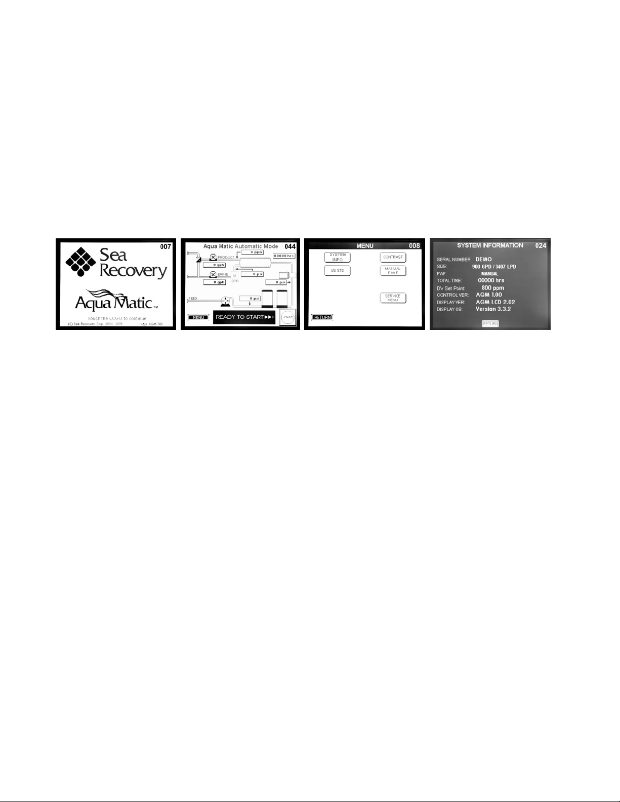
1st Screen007 2
nd Screen044 3
rd Screen008 4
th Screen024
Touch the Logo Touch MENU Touch INFORMATION
SYSTEM INFO
SERIAL NUMBER helps us to determine the latest physical version and configuration of your system which is necessary
to ensure that we provide you with the correct information or parts.
SIZE tells us the production capacity of your system which gives us a bench mark in diagnosing product water flow and
pressure concerns.
FWF tells us if you have installed and are utilizing the Fresh Water Flush feature.
TOTAL TIME assists us in diagnosing abnormalities that can occur at given operational time intervals such as required
pump maintenance, or R.O. Membrane Element condition.
DV Set Point helps us to determine if the R.O. Membrane Element is losing its rejection capabilities or if the 3-Way
Product Water Diversion Solenoid Valve Set Point is simply adjusted too high or too low.
CONTROL VER allows us to determine the specific sequential operation of the system based on the version of the
programmed control logic.
DISPLAY VER and DISPLAY OS assists us in diagnosing problems associated with the Main and Remote Touch
Screen(s).
Notes: __________________________________________________________________________________________
___________________________________________________________________________________________________
___________________________________________________________________________________________________
___________________________________________________________________________________________________
___________________________________________________________________________________________________
___________________________________________________________________________________________________
xv

Aqua Matic 450-1800 Rev. A
SPECIFICATIONS
PERFORMANCE:
PRODUCT WATER PRODUCED PER HOUR AND PER DAY OF OPERATION:
( +-15% at 850 psig / 56 BAR, 77°F / 25°C & 35,000 PPM TDS Feed Water Salinity )
Model Number per 1 hour of operation: per 24 hours of operation:
U.S. Gallons / Liters U.S. Gallons / Liters
SRC Aqua Matic 450-1 18.8 71 450 1703
SRC Aqua Matic 700-1 29.2 110.4 700 2650
SRC Aqua Matic 900-1 37.5 142 900 3407
SRC Aqua Matic 900-2 37.5 142 900 3407
SRC Aqua Matic 1400-2 58.3 220.8 1400 5300
SRC Aqua Matic 1800-2 75 283.9 1800 6814
SALT REJECTION (CHLORIDE ION): 99.4%
PRODUCT WATER TEMPERATURE: Ambient to feed water temperature
SPECIFICATIONS:
SALINITY MONITORING: Automatic computer controlled electronic monitoring. The salinity monitoring
components of the system give a continuous readout in micromhos per cubic centimeter, are temperature
compensated and of a fail-safe design.
SALINITY RANGE OF FEED WATER:
Seawater up to 50,000 PPM TDS (NaCl) (typical seawater salinity is 35,000 PPM)
TEMPERATURE RANGE: Max. 122°F / 50°C, Min. 33°F / .5°C
SYSTEM FEED WATER:
Alternating Current 50 Hz Alternating Current 60 Hz
Feed Water Flow Per Hour: 225 U.S. Gallons / 852 Liters 270 U.S. Gallons / 1,022 Liters
REVERSE OSMOSIS MEMBRANE:
TYPE: Specifically selected High Rejection / High Yield aromatic tri-polyamide, thin film composite, spiral wound,
single pass reverse osmosis membrane element.
CHLORINE TOLERANCE: 0.1 PPM.
pH RANGE: 3-11 (typical seawater pH is 8)
SYSTEM PRESSURE:
FEED WATER: Minimum 6 psi / .42 Kg/cm2. / 41.4 kPa Maximum 40 psi / 2.8 Kg/cm2/ 275.8 kPa
OPERATION: Seawater @ 35,000 PPM & 77°F / 25 C: Nominal 800 psi / / 56.25 Kg/cm2/ 5516 kPa
EXTERNAL INSTALLATION WATER CONNECTIONS:
Pipe sizes to be supplied by the installer for connection of the Sea Recovery supplied components
Aqua Matic
Feed Inlet: 3/4” MNPT Male National Pipe Thread U.S. Standard
Brine Discharge 3/4” MNPT Male National Pipe Thread U.S. Standard
Product 1/2” FNPT Female National Pipe Thread U.S. Standard
xvi

Aqua Matic 450-1800 Rev. A
WEIGHT:
MODEL
Compact Style Vertical Style Modular Style
Aqua Matic 450-1 159 lbs / 72 kg 164 lbs / 74 kg 149 lbs / 67 kg
Aqua Matic 700-1 162 lbs / 73 kg 167 lbs / 75 kg 152 lbs / 68 kg
Aqua Matic 900-1 171 lbs / 77 kg 176 lbs / 79 kg 161 lbs / 73 kg
Aqua Matic 900-2 171 lbs / 77 kg 176 lbs / 79 kg 161 lbs / 73 kg
Aqua Matic 1400-2 177 lbs / 80 kg 182 lbs / 82 kg 167 lbs / 75 kg
Aqua Matic 1800-2 182 lbs / 82 kg 187 lbs / 84 kg 172 lbs / 78 kg
ELECTRICAL MOTOR SPECIFICATIONS:
(H.P. = Horse Power; RPM = Revolutions Per Minute; FLA = Full Load Amperes; LRA = Locked Rotor Amperes @
Start Up)
ALTERNATING CURRENT SYSTEMS:
Single Phase Alternating Current:
High Pressure Pump Motor Booster Pump Motor
VAC Hz H.P RPM FLA LRA H.P RPM FLA LRA
110 50 3 2850 23 89 .5 2850 7.4 20
220 50 3 2850 11.5 44 .5 2850 3.7 10
115 60 3 3450 25.4 86 .5 3450 9.4 20
230 60 3 3450 12.7 43 .5 3450 4.7 10
Three Phase Alternating Current:
High Pressure Pump Motor Booster Pump Motor
VAC Hz H.P RPM FLA LRA H.P RPM FLA LRA
220 50 2.5 2850 7.9 24.9 .5 2850 2.5 8.2
380 50 2.5 2850 4.6 14.4 .5 2850 1.5 4.7
230 60 3 3450 7.6 23.8 .5 3450 2.4 7.9
460 60 3 3450 3.8 11.9 .5 3450 1.2 3.9
RECOMMENDED CIRCUIT BREAKER SUPPLYING POWER TO SYSTEM AMPERAGE RATING:
Operating Recommended
AC Voltage Phase Circuit Breaker
110 - 115 VAC Single 50 Ampere
220 - 230 VAC Single 25 Ampere
220 VAC Three 15 Ampere
380 VAC Three 10 Ampere
460 VAC Three 10 Ampere
RECOMMENDED POWER WIRE SIZE TO Aqua Matic SYSTEM:
Operating Phase Maximum Recommended Minimum Wire Size for Length of run
Voltage Load
10 Ft / 3 meter 25 Ft / 8 meter 50 Ft / 15 meter
110-115 VAC Single 34.8 Ampere 10 AWG / 6 mm28 AWG / 10 mm28 AWG / 10 mm2
220-230 VAC Single 17.4 Ampere 12 AWG / 4 mm212 AWG / 4 mm212 AWG / 4 mm2
220-230 VAC Three 10.4 Ampere 14 AWG / 2.5 mm214 AWG / 2.5 mm214 AWG / 2.5 mm2
380 VAC Three 6.1 Ampere 14 AWG / 2.5 mm214 AWG / 2.5 mm214 AWG / 2.5 mm2
460 VAC Three 5 Ampere 14 AWG / 2.5 mm214 AWG / 2.5 mm214 AWG / 2.5 mm2
xvii

Aqua Matic 450-1800 Rev. A
xviii
RECOMMENDED POWER WIRE SIZE TO Aqua Matic BOOSTER PUMP:
Operating Phase Maximum Recommended Minimum Wire Size for Length of run
Voltage Load
10 Ft / 3 meter 25 Ft / 8 meter 50 Ft / 15 meter
110-115 VAC Single 9.4 Ampere 14 AWG / 2.5 mm214 AWG / 2.5 mm214 AWG / 2.5 mm2
220-230 VAC Single 4.7 Ampere 14 AWG / 2.5 mm214 AWG / 2.5 mm214 AWG / 2.5 mm2
220-230 VAC Three 2.5 Ampere 16 AWG / 1.5 mm216 AWG / 1.5 mm216 AWG / 1.5 mm2
380 VAC Three 1.5 Ampere 16 AWG / 1.5 mm216 AWG / 1.5 mm216 AWG / 1.5 mm2
460 VAC Three 1.2 Ampere 16 AWG / 1.5 mm216 AWG / 1.5 mm216 AWG / 1.5 mm2
RECOMMENDED POWER WIRE SIZE TO Aqua Matic HIGH PRESSURE PUMP:
Operating Phase Maximum Recommended Minimum Wire Size for Length of run
Voltage Load
10 Ft / 3 meter 25 Ft / 8 meter 50 Ft / 15 meter
110-115 VAC Single 25.5 Ampere 12 AWG / 4 mm210 AWG / 6 mm210 AWG / 6 mm2
220-230 VAC Single 12.7 Ampere 14 AWG / 2.5 mm212 AWG / 4 mm212 AWG / 4 mm2
220-230 VAC Three 7.9 Ampere 14 AWG / 2.5 mm214 AWG / 2.5 mm214 AWG / 2.5 mm2
380 VAC Three 4.6 Ampere 14 AWG / 2.5 mm214 AWG / 2.5 mm214 AWG / 2.5 mm2
460 VAC Three 3.8 Ampere 14 AWG / 2.5 mm214 AWG / 2.5 mm214 AWG / 2.5 mm2
Other manuals for SRC Aqua Matic 450-1
1
This manual suits for next models
5
Table of contents
Other Sea Recovery Marine Equipment manuals


