SEA 23105198 User manual

Sistemi Elettronici
di Apertura Porte e Cancelli
International registered trademark n. 804888
®
PUSH
(cod. 23105198)
VANDAL RESISTANT BACK-LIT
WEATHERPROOF ACCESS CONTROL KEYPAD
For electric lock, inter-lock and security system installations
English
Rev. 01 - 05/201167411245
SEA S.p.A.
Zona industriale 64020 S.ATTO Teramo - (ITALY)
Tel. +39 0861 588341 r.a. Fax +39 0861 588344
www.seateam.com

Sistemi Elettronici
di Apertura Porte e Cancelli
International registered trademark n. 804888
®
PUSH
TABLE OF CONTENTS
English
Rev. 01 - 05/2011674112452
INTRODUCTION.........................................................................................................................................................3
FEATURES..................................................................................................................................................................3
SPECIFICATIONS.......................................................................................................................................................3
INSTALLATION............................................................................................................................................................4
Precautions......................................................................................................................................................4
Package Contents............................................................................................................................................4
CONNECTION TERMINALS.......................................................................................................................................4
The On-Board LED Indicators...........................................................................................................................6
The Pacier Tones & The LED Signals................................................................................................................6
The Jumper for Back-Lit Selection....................................................................................................................6
FEATURE PROGRAMMING & OPERATION INSTRUCTIONS...................................................................................7
Set System in Programming Mode with The Master Code.................................................................................7
Direct Access to Programming Mode with The “DAP” Code – 8 0 8 0..................................................................7
Refresh The System with The “Refreshing Code” --- 9 9 9 9...............................................................................8
The Default Values of The Keypad....................................................................................................................8
KEYPAD PROGRAMMING MAKE SIMPLE – For General Users.................................................................................9
FEATURE PROGRAMMING -- KEY INAND STORE THE DESIRED VALUES.............................................................10
Programming Criteria for Codes.......................................................................................................................10
Record A Master Code......................................................................................................................................11
Record A Super User PIN..................................................................................................................................11
Operation And Functions of The Super User PIN...................................................................................11
Record-Delete PINs for Output 1, 2, & 3............................................................................................................12
Examples – Programming And Operation.............................................................................................12
Visitor Codes (For Output 1 Only).....................................................................................................................14
Duress Codes (For Outputs 1, 2 & 3).................................................................................................................15
The Operation And Function of The Duress Code.................................................................................16
Conguration of The Output Modes for Output 1, 2 And 3....................................................................................16
Personal Safety And System Lock-Out.............................................................................................................16
User PIN Entry Mode........................................................................................................................................17
Pacier Tones On-Off Selection..........................................................................................................................17
Output Operation Announcer............................................................................................................................17
Status LED Flashing On-Off during Standby......................................................................................................18
Door Forced Open Warning & Timing................................................................................................................18
Door Propped-Up Warning & The Delay Time...................................................................................................18
Intelligent Egress Button – An Unique Feature of AContemporary Keypad........................................................19
Egress Delay , Warning And Alarm....................................................................................................................19
Congurations of The Egress WarningAnd Alarm...................................................................................19
Door OpeningAlarm & Timer.............................................................................................................................20
Close The Programming Mode.........................................................................................................................21
PROGRAMMING SUMMARY CHART.........................................................................................................................21
APPLICATION EXAMPLES.........................................................................................................................................23
Basic Wirings of A Stand Alone Door Lock.........................................................................................................23
Basic Wirings of AStandAlone Door Lock with Inhibit Authorization Code.........................................................24
Basic Wirings of An Inter-Lock System Using Two Keypads..............................................................................25
APPLICATION HINTS FOR THEAUXILIARY TERMINALS..........................................................................................26
APPENDIX...................................................................................................................................................................28

Sistemi Elettronici
di Apertura Porte e Cancelli
International registered trademark n. 804888
®
PUSH
English
INTRODUCTION
FEATURES
SPECIFICATIONS
The keypad unit comes with plenty of functions for owner’s selection via programming. Owners can take them freely to tailor the
desired features for their system. It is an ideal keypad mainly for Door Strike and Alarm Arm-disarm control. It is also a
programmable industrial timer (with the timing of 1 second to over 24 hours) for Automatic Operator Systems.
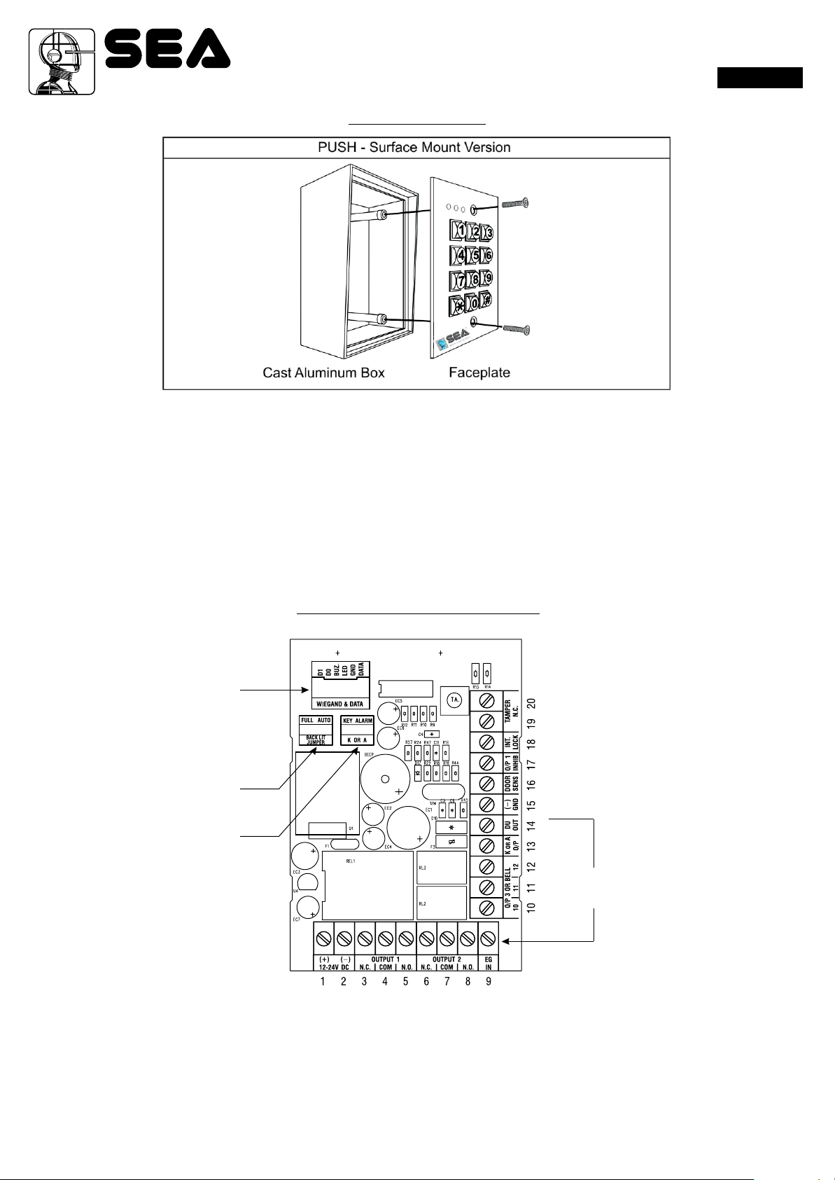
PUSH – Output Relays for Output 1, 2 and 3 (Surface Mount Version)
• Indoor or outdoor installation
• StandAlone or Inter-lock system built-in with all the required control logics
• Controls “Going in” with User PIN and “Going out” with programmable egress button
• Durable Steel housing for surface or gooseneck mounting (code: 12710208)
• Built-in Tamper Switch
• Heavy duty 1.5mm stainless steel faceplate
• Die-casting metal back-lit keyboard with dual brightness levels
• Vandal resistant and weatherproof (IP-66)
• Three outputs controlled by independent groups of codes / PINs
• Programmable Timers for Door Strike,AlarmArm-disarm Control or IndustrialAutomatic Operators.
Operating Voltage: 12V-24V DC,Auto adjusting
Operating Current: 40mA(quiescent) to 100mA(three relays active)
Operation Temperature: -20 C to +70 C
Environmental Humidity: 5-95% relative humidity non-condensing
Working Environment & Ingress Protection: All weather, IP-66
Number of Users: Output 1 – 1,000 User PINs + 50 Duress Codes
Output 2 – 100 User PINs + 10 Duress Codes
Output 3 – 100U ser PINs + 10 Duress Codes
Number of Visitor Codes: 50, programmable for one time or with the time limit
Timings for Code Entry: 10 seconds waiting for next digit entry
The Timers: Three 1-99,999 Seconds (Over 24 Hours possible) Independent Programmable Timers
for O/P 1, 2 & 3
Egress Button: Programmable for Instant, Delay with Warning and/or Alarm
Momentary or Holding Contact for the Exit Delay
Input Sensing Terminals: a) Door position, b) Egress, c) O/P 1 inhibit
Output Control Terminals : Transistor Open Collector 24VDC/100mA sink Max for the following
outputs a) Duress, b) Alarm, c) KeyActive,
d) Output 3 (Door Bell version only), e) Inter-lock
Output Contact Ratings: Output Relay 1 – N.C. & N.O. dry contacts, 5A/24VDC Max.
Output Relay 2 – N.C. & N.O. dry contacts, 1A/24VDC Max.
Output Relay 3 – N.C. & N.O. dry contacts, 1A/24VDC Max. (N.O. contact only for Door
Bell version)
Tamper Switch – N.C. dry contact, 50mA/24VDC Max.
Dimensions: PUSH – 125(H) X 79(W) X 46/54(D)mm
Weight: PUSH – 550g net
Housing: PUSH - CastAluminum, Power paint coating
Faceplate Material: 1.5mm stainless steel
Specications are subject to change for modication without notice
Rev. 01 - 05/201167411245 3
Sistemi Elettronici
di Apertura Porte e Cancelli
International registered trademark n. 804888
®
PUSH
English
WIEGAND & DATA
I/O HARNESS
BACK-LIT JUMPER
K OR A JUMPER
CONNECTION
TERMINALS
INSTALLATION
PRECAUTIONS
Please be patient to study the manual to become familiar with the specications of the system before starting the installations.
1) Do not apply power to the system while it is in installation.
2) Check carefully all the wirings are correct before applying power to the system for testing.
PACKAGE CONTENTS
• One unit Keypad
• One pack of Mounting Screws
• One Centre Pin Torx Screw Wrench
• One Wire Harness ( Six wires)
• One Programming & Installation Manual
CONNECTION TERMINALS
• 1 - 2 : 12-24V DC (Power Input Terminal)
Connect to 12-24V DC power supply. The (-) supply and the (-) GND are the common grounding points of the system.
The system accepts full input voltage range with no jumper selection.
• 3 - 4 - 5 : OUTPUT 1 (Output Relay 1)
5 Amp relay dry contact controlled by the Group 1 User PINs for Output 1, recommended for door strike. Terminal 3 is Normally
Closed (N.C.), terminal 5 is Normally Open (N.O.) and terminal 4 is the common point of the two contacts.
Use N.C. output for “Fail-safe” locking device; and N.O. output for “Fail-secure” locking device. The relay is programmable for
Start/Stop (toggle) mode or Momentary timing mode. See programming Location 51 for the details.
Rev. 01 - 05/2011674112454

Sistemi Elettronici
di Apertura Porte e Cancelli
International registered trademark n. 804888
®
PUSH
English
• 6 - 7 - 8 : OUTPUT 2 (Output Relay 2)
1 Amp relay dry contact controlled by the Group 2 User PINs for Output 2, it is an auxiliary output ideally for controlling security
system or automatic operator. Terminal 6 is Normally Closed (N.C.), terminal 8 is Normally Open (N.O.) and terminal 7 is the
common point of the two contacts. The relay is programmable for Start/Stop (toggle) mode or Momentary timing mode. See
programming Location 52 for the details.
• 9 : EG IN ( Egress Input)
A Normally Open (N.O.) input terminal referring to (-) ground. With the help of connecting a normally opened button to activate
Output 1 for door opening in the same manner of using the Group 1 User PINs. Egress button is usually put inside the house near
the door. More than one egress buttons can be connected in parallel to this terminal. Leave this terminal open if not used.
See Programming Locations 90 and 91 for more information about the Egress Button with other features.
• 10 - 11 - 12 : OUTPUT 3 (Output Relay 3)
1 Amp relay dry contact controlled by the Group 3 User PINs for Output 3, it is an auxiliary output ideally for controlling security
system or automatic operator. Terminal 10 is Normally Closed (N.C.), terminal 12 is Normally Open (N.O.) and terminal 11 is the
common point of the two contacts. The relay is programmable for Start/Stop (toggle) mode or Momentary timing mode. See
programming Location 53 for the details.
• 13 : “K” OR “A” O/P (KeypadActive Output orAlarm Output)
An NPN transistor open collector output with the maximum power rating of 24VDC/100mA sink. It is equivalent to an N.O.
(Normally Open) terminal referring to ground. It can be used to drive small power device, such as a relay or a low power control
point for other equipment. This output point is selectable to give Keypad Active Output or Alarm Output via the Selection of the “K
orA” jumper.
a) Keypad Active Output (“K”) --- It switches to ( -) ground for 10 seconds on each key touch. It can be used to turn on light,
CCTV camera, or buzzer to notify a guard. See Application Hints for more information.
b) Alarm Output (“A”) --- It switches to ( -) ground while Alarm occurs in order to trigger external alarm to give notication at
remote location.
• 14 : DU OUT (Duress Output)
An NPN transistor open collector output with the maximum power rating of 24VDC/100mA sink. It is equivalent to an N.O.
(Normally Open) terminal switching to (-) ground after the Duress Code is entered. Use it to trigger an alarm zone of a security
system, or turn on a buzzer to notify a guard.
• 15 : ( - ) GND (Common Ground)
Agrounding point of the keypad that is common to terminal 2.
• 16 : DOOR SENS N.C. (Door Position Sensing Input -- Normally Close)
A Normally Closed (N.C.) sensing point referring to ( - ) ground, with the help of a normally closed magnetic contact monitors the
open or close status of the door. It initiates the following functions for the system. Connect it with jumper to (-) Ground if not used.
a) DoorAuto Re-lock
The system immediately re-locks the door after it is re-closed before the end of the programmed time for output 1. It
prevents unwanted “tailgate” entry.
b) Door Forced Open Warning
The keypad generates “door forced open” warning and alarm instantly once the door is forced to open without a valid user
PIN or egress button. The warning lasts as long as the time programmed (1 - 999 sec). It can be stopped with an User PIN
for output 1 at anytime. See programming Location 80 for the details.
C) Door Propped-up Warning
The keypad generates propped-up warning beeps (does not activates alarm output) while the door is left open longer than
the allowable time programmed. The warning will last as long as the door is open until re-closed. See programming
Location 81 for the details.
d) Inter-lock Control
The inter-lock control output always goes to ( - ) while the door is open, which gives signal to disable the other keypad in
the inter-lock system. See the Inter-lock terminal description for more information.
e) Door OpeningAlarm
Door Opening Alarm is designed for the emergency door only. It is always given when the door is opened unless a valid
user code or card is used prior to the door is opened. See programming Location 91 for the details.
• 17 : O/P 1 INHIBIT N.O. (Output 1 Inhibit Control Input – Normally Open)
A Normally Open (N.O.) sensing input point for controlling the Output 1, with this terminal connecting to ( - ) ground, the Egress
Button, the group of User PINs for Output 1 are all disabled. It is prepared mainly for the cross wire connection with the “Inter-lock
O/P” point on the other keypad in an Inter-lock system.
NOTE: The inhibit function does not govern the Duress Codes and the Super User Codes. They are always valid.
Rev. 01 - 05/201167411245 5
This manual suits for next models
1
Table of contents
Other SEA Keypad manuals


