Seakeeper 18 User manual

December 2019, Revision 1
OPERATION MANUAL
*THIS MANUAL ALSO COVERS THE SEAKEEPER 16 MODEL*
NOTE: THIS APPLIES TO SEAKEEPER 16 MODELS AFTER SERIAL No. 16-201-XXXX or LATER

OPERATION
MANUAL
Product:
Document #:
Rev:
SEAKEEPER 16 / 18
90550
1
SEAKEEPER 16 / 18
OPERATION MANUAL
DECEMBER 2019
Contents:
Section 1 –System Overview
Section 2 –System Operation
Section 3 –Power Failures, Alarms, and Troubleshooting
Section 4 –Maintenance
Section 5 –Warranty, Limit of Liability, Property Rights
Section 6 –Specs and Summary
45310 ABELL HOUSE LANE, SUITE 350
CALIFORNIA, MARYLAND, 20619, U.S.A
PHONE: 410-326-1590
E-MAIL: contact@seakeeper.com

OPERATION
MANUAL
Product:
Document #:
Rev:
Page:
SEAKEEPER 16 / 18
90550
1
1 of 9
Section 1: SYSTEM OVERVIEW
1.0 System Overview
The Seakeeper 16/18 uses gyroscopic principles to reduce boat roll motions in waves and wakes
independent of boat speed. In multiple Seakeeper installations, the Seakeepers operate
independently of each other and therefore this manual only discusses operation of a single unit.
A Seakeeper 16/18 consists of a Gyro assembly, a CAN communications cable (30243 and
30301), and a Display (30298). Figure 1 illustrates the interconnection of these components and
their interface with the boat.
FIGURE 1 –SEAKEEPER 16/18 STABILIZATION SYSTEM COMPONENTS
Technical specifications provided in Section 6 list the power consumption, total weight, and
dimensions of the major components. Gyroscopic principals that apply to boat roll control are
discussed on Seakeeper’s web site at www.seakeeper.com. The Seakeeper website also
contains videos of Seakeeper operation and videos of several different boats operating in waves
with the Seakeeper on and off. It is recommended that the reader play these videos prior to
reading the remainder of this manual.

OPERATION
MANUAL
Product:
Document #:
Rev:
Page:
SEAKEEPER 16 / 18
90550
1
2 of 9
Section 1: SYSTEM OVERVIEW
The gimbal angle and the rate of rotation about the gimbal axis (termed precession rate) play an
important role in its operation. These parameters are illustrated in Figure 2. At zero-degree
gimbal angle, the sphere is vertical; it can precess a maximum of +/- 70 degrees about this
position. The amount of torque that the Seakeeper exerts on a boat’s hull to counter the wave
induced roll is directly proportional to the precession rate because the torque is exerted
perpendicular to axis of the flywheel. The further the Seakeeper is from vertical (zero degrees)
the lower the anti-roll torque. The vertical arrows in Figure 2 illustrate the direction of the forces
that the Seakeeper exerts on the boat’s hull to damp roll motion.
FIGURE 2 –SEAKEEPER PRECESSION
Seakeeper precession is actively controlled by an electronic controller and a hydraulic brake
throughout each roll cycle so the Seakeeper supplies the maximum anti-roll torque and does not
make mechanical contact with hard stops that limit the maximum gimbal angle travel to +/- 70o.

OPERATION
MANUAL
Product:
Document #:
Rev:
Page:
SEAKEEPER 16 / 18
90550
1
3 of 9
Section 1: SYSTEM OVERVIEW
There is a large torque about the gimbal axis when the Seakeeper is
precessing. Seakeeper cover panels are provided to prevent personnel or
equipment from contacting the Seakeeper while it is in operation. These
covers should not be stood on or have anything placed on top. The covers
should always be in place during operation. If it is ever necessary to touch
the Seakeeper while the flywheel is spinning, the Seakeeper must be
locked at the display to stop the Seakeeper from precessing. Seakeeper
maintenance should not be attempted unless the Seakeeper is locked and
the flywheel has stopped spinning.

OPERATION
MANUAL
Product:
Document #:
Rev:
Page:
SEAKEEPER 16 / 18
90550
1
4 of 9
Section 1: SYSTEM OVERVIEW
1.1 Seakeeper Assembly
The Seakeeper assembly consists of a flywheel housed in a cast aluminum vacuum-tight
enclosure. The flywheel spins about a vertical axis and is supported by upper and lower pairs of
bearings. A DC brushless motor mounted inside the enclosure spins the flywheel at high speed.
The enclosure is fastened to two gimbal shafts that are supported by gimbal bearings on either
side. These shafts establish an athwart ship gimbal axis about which the flywheel and enclosure
precess or rotate up to +/- 70 degrees during operation. The gimbal bearings are supported by a
foundation which is attached to the hull structure. This foundation transfers the loads that the
Seakeeper produces to the hull structure.
An active hydraulic brake mechanism is located on the Seakeeper assembly to regulate the
Seakeeper’s precession motions about the gimbal shaft. It includes four hydraulic cylinders and
a hydraulic manifold.
A coolant pump and heat exchanger with reservoir are located near the manifold. A glycol/water
mix is circulated through a closed loop to the motor drive box, hydraulic manifold, and the end
caps of the flywheel enclosure to remove heat.
FIGURE 3 –SEAKEEPER ASSEMBLY

OPERATION
MANUAL
Product:
Document #:
Rev:
Page:
SEAKEEPER 16 / 18
90550
1
5 of 9
Section 1: SYSTEM OVERVIEW
1.2 Display
The display shown below is the user interface to the Seakeeper 16/18 and should be mounted at
the primary helm station, unless the vessel has compatible Multi-Function Display, in which case
the Seakeeper Display can be mounted elsewhere. It is used to start, operate, monitor and
shutdown the Seakeeper. Sensors, alarms and shutdowns are provided to allow unattended
operation. However, the Seakeeper is a high-speed machine and special attention should be
paid to abnormal vibration and noise as this could be the first hint of a mechanical problem.
The display provides information in the event of an alarm. Alarms automatically cause precession
to stop (LOCK) and the Seakeeper to start coasting down (STOP).
FIGURE 4 –OPERATOR DISPLAY

OPERATION
MANUAL
Product:
Document #:
Rev:
Page:
SEAKEEPER 16 / 18
90550
1
6 of 9
Section 1: SYSTEM OVERVIEW
1.3 Drive Box
The glycol/water mix that cools the Seakeeper is also circulated through a cold plate inside the
Drive Box to remove heat from high-power electronic components.
The Motor Drive Box contains hazardous voltage and the
cover should not be removed while the flywheel is spinning,
and the AC input voltage is present. This high voltage exists
even if the flywheel is coasting down and the supply voltage
has been shut off. The flywheel must be at Zero (0000) RPM
and AC input power disconnected for at least 10 minutes
prior to any service work on the motor drive box.
FIGURE 5 –DRIVE BOX

OPERATION
MANUAL
Product:
Document #:
Rev:
Page:
SEAKEEPER 16 / 18
90550
1
7 of 9
Section 1: SYSTEM OVERVIEW
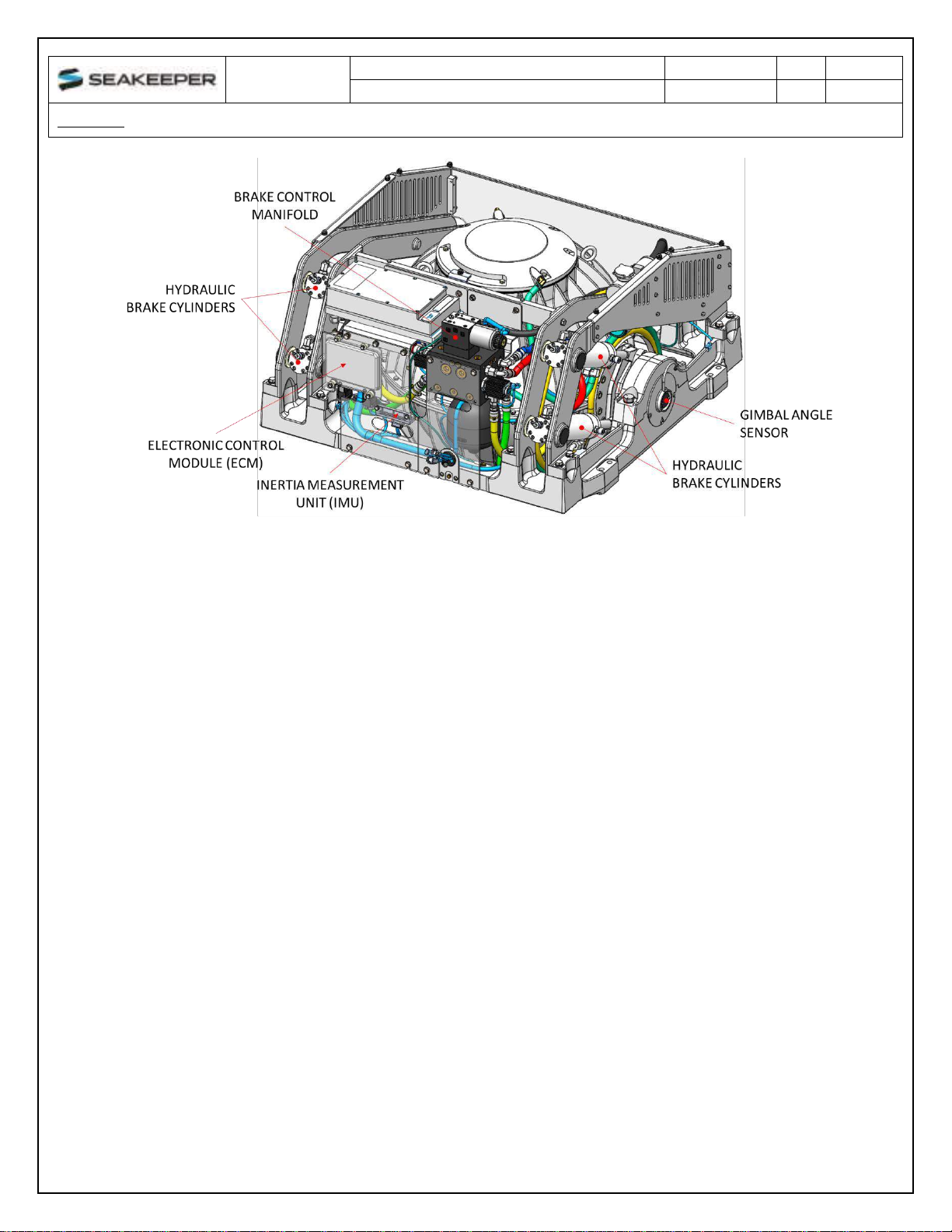
1.4 Electronic Control Module
The Electronic Control Module (ECM) monitors all the system sensors and automatically regulates
operation of the Seakeeper.
The controller commands the motor speed and regulates the Seakeeper’s precession rate and
gimbal angle. This is accomplished by commands to a high response flow control valve in the
hydraulic brake circuit that increases or decreases the brake pressure.
1.5 Inertia Measurement Unit (IMU)
The motion sensor suite in the IMU measures the angular movements of the vessel and the
vertical and lateral boat movement. These signals are communicated to the ECM through the
Seakeeper’s wiring harness.
1.6 Brake
The brake mechanism consists of four hydraulic cylinders that attach to crank arms on the
Seakeeper gimbal shafts. The Seakeeper controller modulates how fast the oil can flow through
a control valve thus controlling the precession rate of the Seakeeper.
The brake hydraulic circuit is a pre-charged closed loop system –that is, there is no pump, motor
or reservoir in the circuit. An accumulator is installed in the circuit, so the pre-charge pressure
does not increase as the fluid temperature rises due to the braking action. Locking solenoid
valves are installed in the circuit to lock the Seakeeper, so it cannot precess if there are any
alarms or a mechanical problem with the Seakeeper.

OPERATION
MANUAL
Product:
Document #:
Rev:
Page:
SEAKEEPER 16 / 18
90550
1
8 of 9
Section 1: SYSTEM OVERVIEW
FIGURE 6 –BRAKE SYSTEM COMPONENTS

OPERATION
MANUAL
Product:
Document #:
Rev:
Page:
SEAKEEPER 16 / 18
90550
1
9 of 9
Section 1: SYSTEM OVERVIEW
1.7 Cooling
The cooling circuit is a closed loop that supplies a glycol/water (50% distilled water and 50%
glycol) mix to:
•The motor drive box to remove heat from the drive electronics
•The brake manifold to remove heat from the brake hydraulic circuit
•The flywheel enclosure water jackets to remove heat from the flywheel bearings
The circuit also contains a coolant reservoir for coolant expansion and to make filling easy. The
reservoir contains a 7 psi (0.5 bar) pressure cap. The heat exchanger contains zinc anodes that
must be inspected and changed regularly to ensure maximum heat exchanger life.
FIGURE 7 –COOLING SYSTEM COMPONENTS

OPERATION
MANUAL
Product:
Document #:
Rev:
Page:
SEAKEEPER 16 / 18
90550
1
1 of 12
Section 2: SYSTEM OPERATION
2.0 Introduction
This section describes operation of the Seakeeper 16/18 system.
2.1 Display Screens: Overview
1) When 24 VDC is applied to the Seakeeper the DISPLAY will power up and initialize. The
SPLASH screen will be displayed
2) After the DISPLAY has initialized the HOME screen will be displayed

OPERATION
MANUAL
Product:
Document #:
Rev:
Page:
SEAKEEPER 16 / 18
90550
1
2 of 12
Section 2: SYSTEM OPERATION
3) The display uses a touch screen to allow users to select functions.
•Seakeeper On/Off. The button will change from grey (Seakeeper Off) to blue
(Seakeeper On)
Seakeeper Stabilize On/Off. The button will change from grey (Stabilize Off) to
blue (Stabilize On) once the flywheel reaches the stabilization RPM
Home screen view. These buttons toggle home screen between the Roll Angle
Gauge and the Roll Angle Graph as shown below.

OPERATION
MANUAL
Product:
Document #:
Rev:
Page:
SEAKEEPER 16 / 18
90550
1
3 of 12
Section 2: SYSTEM OPERATION
4) When the menu button is pressed, the menu bar will appear or disappear at the bottom
of the screen.
The menu bar is used to navigate between pages. From left to right, the available pages
are Home, Settings, Information, Service and Alarm History. The selected page is
highlighted in blue on the menu bar.
5) The Settings page allows the user to adjust the following:

OPERATION
MANUAL
Product:
Document #:
Rev:
Page:
SEAKEEPER 16 / 18
90550
1
4 of 12
Section 2: SYSTEM OPERATION
a) Increase or decrease the brightness of the display with the brightness slider.
b) Adjust the sleep timer from 1 minutes to 60 minutes or on all the time using sleep
time slider. Touching the screen will wake the display up after it has gone to
sleep.
c) Change the sign of the roll angle value displayed in the roll angle gauge so the
gauge matches the motion of the boat. This will depend on installation orientation
and will only need to be adjusted once.
•Backward Facing, Seakeeper installation orientation
•Forward Facing, Seakeeper installation orientation

OPERATION
MANUAL
Product:
Document #:
Rev:
Page:
SEAKEEPER 16 / 18
90550
1
5 of 12
Section 2: SYSTEM OPERATION
d) Change the speed of the Seakeeper between normal operation and low power
operation. The selected speed is colored blue. When power is cycled (or
Seakeeper turned Off), this speed will default back to the normal operating
speed. Speed selection buttons shown below are examples and may not match
operating speed of installed Seakeeper.
Seakeeper 18:
Seakeeper 16:
e) Change the display between day and night mode. The selected mode is colored
blue.
f) Change the units of the temperatures displayed on the service page between
degrees Celsius and degrees Fahrenheit. The selected units are colored blue.
6) The information page displays the Seakeeper model, Seakeeper serial number,
Seakeeper software versions, RUN hours, and SEA hours, and other information.

OPERATION
MANUAL
Product:
Document #:
Rev:
Page:
SEAKEEPER 16 / 18
90550
1
6 of 12
Section 2: SYSTEM OPERATION
7) The service page displays operating information from the Seakeeper.
8) The alarm history page shows what alarms have occurred in the past and the
associated run hours. The scroll bar is used to move up and down through the list.

OPERATION
MANUAL
Product:
Document #:
Rev:
Page:
SEAKEEPER 16 / 18
90550
1
7 of 12
Section 2: SYSTEM OPERATION
2.2 Start-up
1) Make sure AC and DC power are available.
2) Turn on the boat’s DC circuit breaker(s) that supplies power to the Seakeeper controls
and seawater pump.
a. In most cases, the seawater pump will be wired to turn on when the Seakeeper is
turned on. However, in some cases the seawater pump is on a separate DC
circuit breaker and it is necessary to turn it on.
3) Turn on the boat’s AC circuit breaker that supplies power to the Seakeeper.
4) When the DC power is turned on the DISPLAY will initialize, and the HOME screen will
appear. If a FAULT is present an ALARM screen will appear.
To turn the Seakeeper on, press the On/Off button, the button will turn blue. The
progress bar will appear and indicate how soon the Seakeeper will be available for
stabilization. When the Seakeeper is initialized and up to minimum operating speed the
stabilize button will appear. At this point, the Seakeeper is available for stabilization.

OPERATION
MANUAL
Product:
Document #:
Rev:
Page:
SEAKEEPER 16 / 18
90550
1
8 of 12
Section 2: SYSTEM OPERATION
5) When the Seakeeper reaches its maximum operating speed where maximum
stabilization is available, the progress bar will disappear and the Seakeeper is available
for maximum stabilization.

OPERATION
MANUAL
Product:
Document #:
Rev:
Page:
SEAKEEPER 16 / 18
90550
1
9 of 12
Section 2: SYSTEM OPERATION
2.3 Stabilization
To stabilize the boat after Seakeeper is on and above the minimum operating speed:
1) Press the stabilize button. The button will turn blue indicating that the Seakeeper is
stabilizing the roll motion. The stabilization mode starts gradually; it takes 5-10 seconds
to reach full effectiveness.
Other manuals for 18
1
This manual suits for next models
1
Other Seakeeper Industrial Equipment manuals
Popular Industrial Equipment manuals by other brands

parr
parr 1108 Operating instructions manual

KegLand
KegLand NukaTap KL21760 instruction manual

Industrial Vacuum Equipment
Industrial Vacuum Equipment HURRICANE 500 Operator's manual

schmersal
schmersal AZM201Z-I2-ST2-T-1P2PW-A Operating & assembly instructions

Siemens
Siemens LI-Z-BV Series installation instructions

Schmalz
Schmalz SSP operating manual