Procedure: ANNUAL INSPECTION INSTRUCTIONS
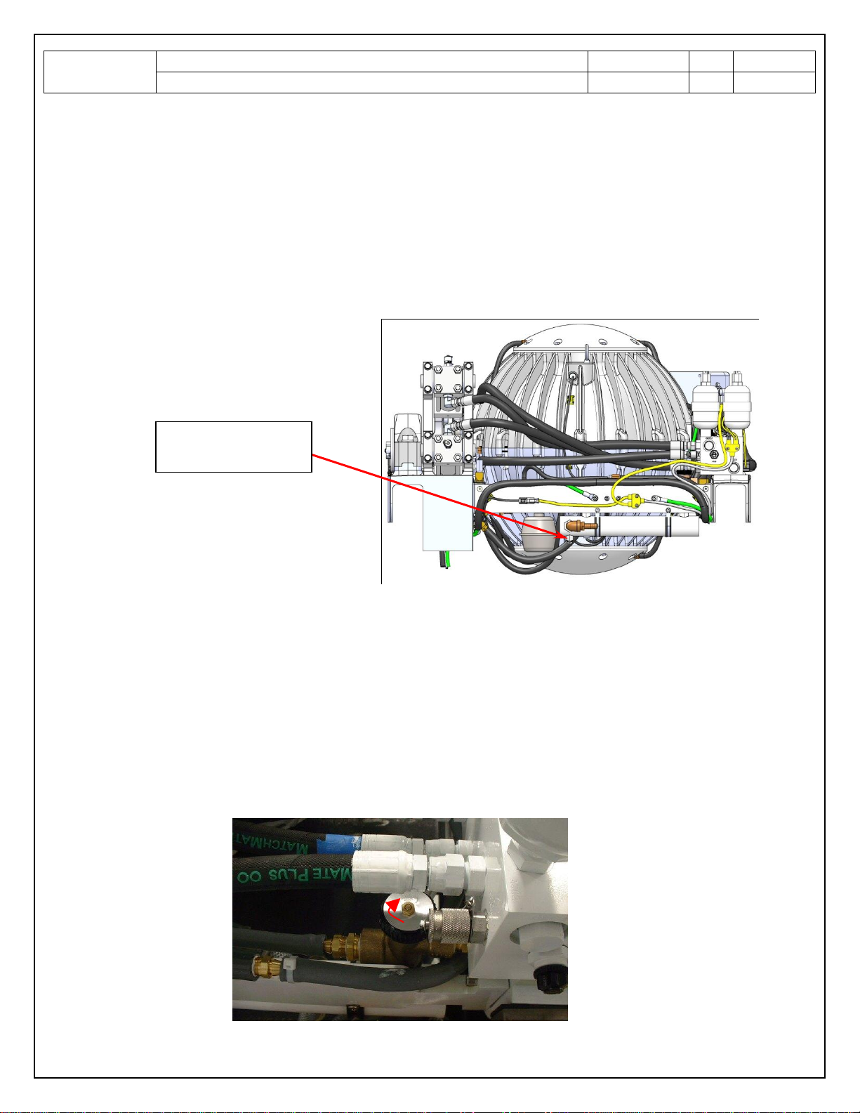
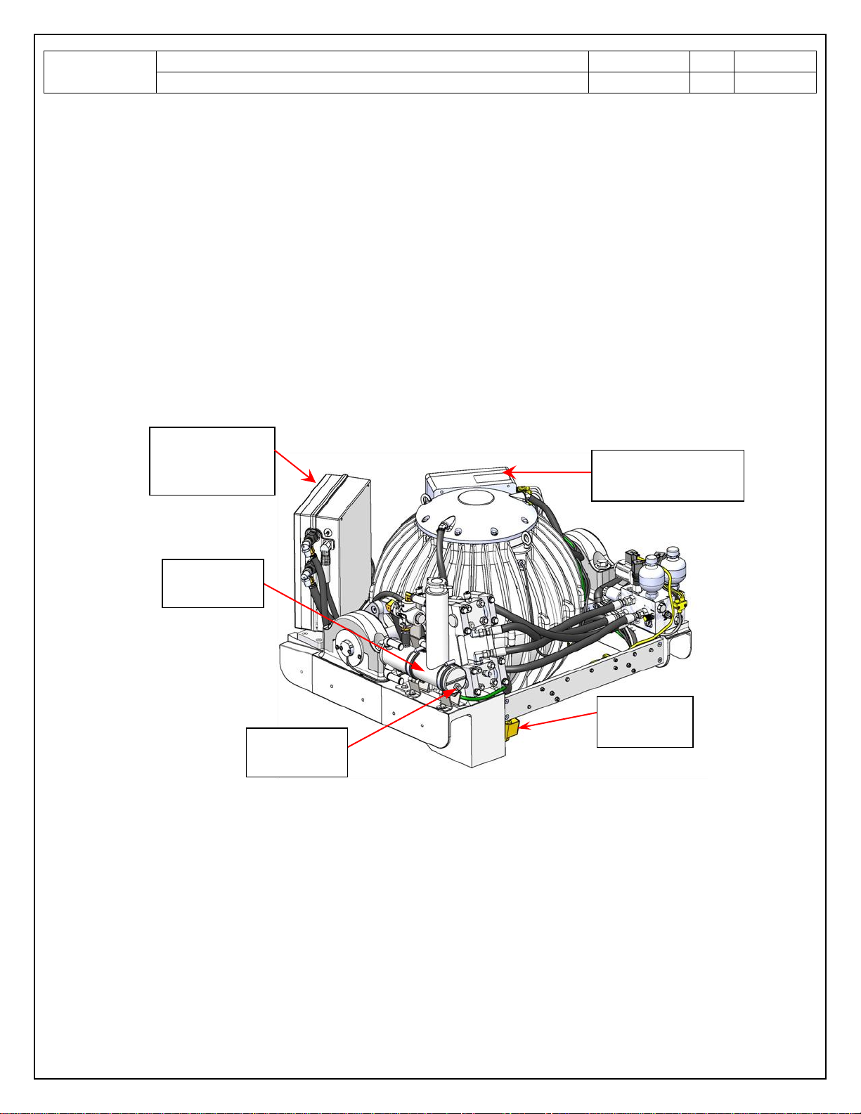
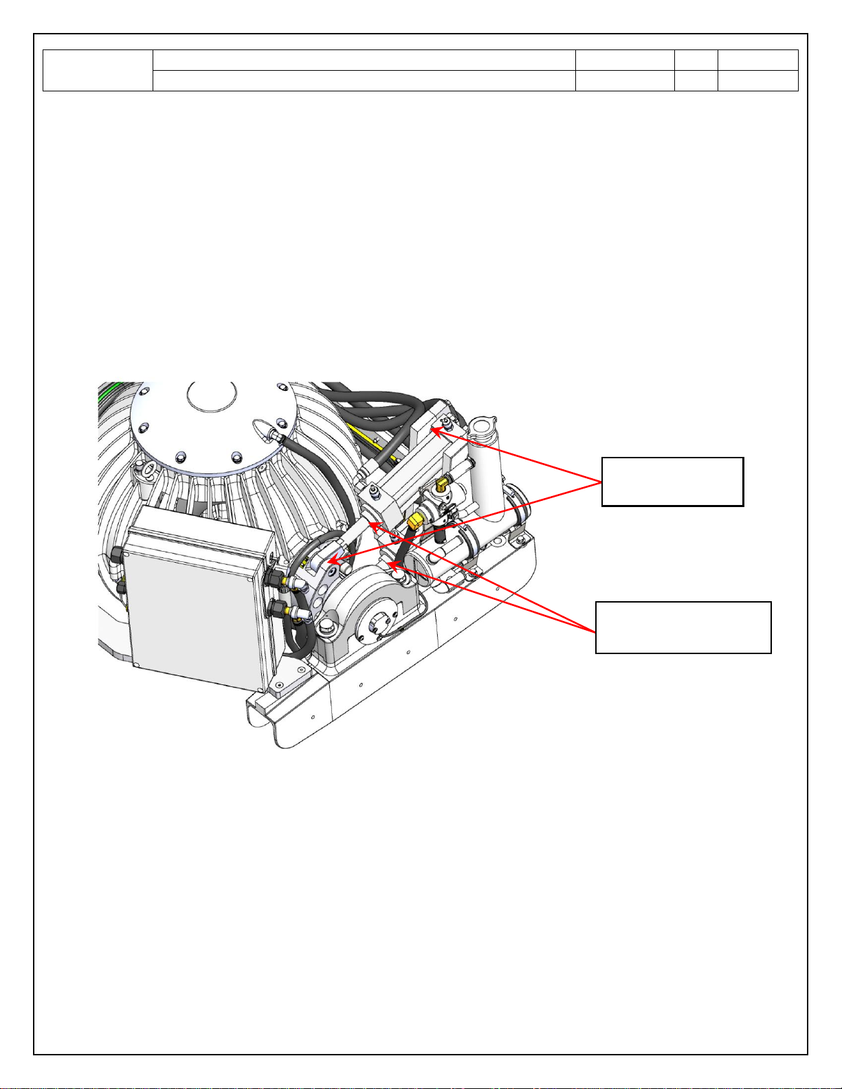
Inspect heat exchanger and fittings for any leaks or severe corrosion. The heat exchanger is
located alongside the brake cylinders on the units foundation as shown in below image. Insure
seawater cooling hoses are isolated from incoming seawater (i.e: close sea-cock) and disconnect
seawater inlet and outlet hoses. Remove plug containing zinc anode on the heat exchanger and
inspect. If erosion is estimated to be more that 50%, replace anode. If zinc anode is gone, make
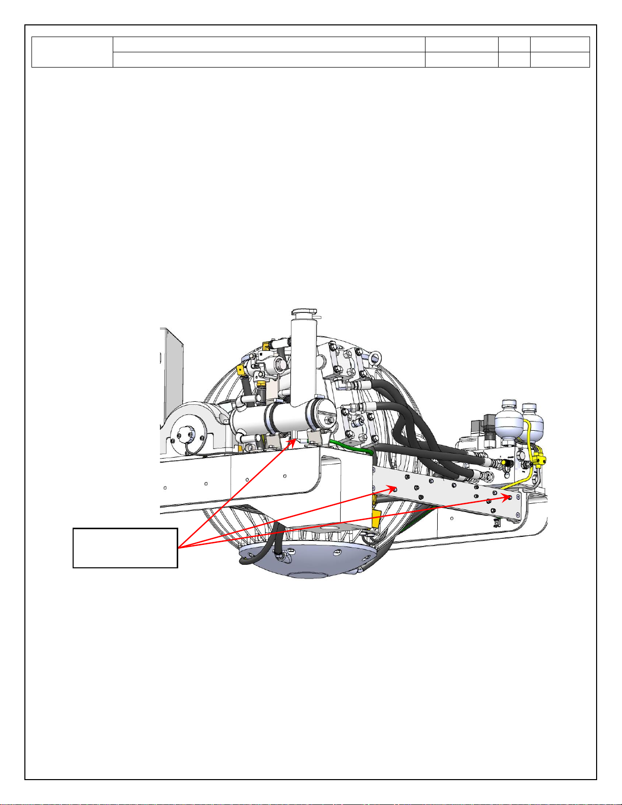
point to inspect every 2 months until erosion rate is determined. The anode is a 3/8 inch diameter x
¾ inch long pencil in a ¼” NPT plug. Contact Seakeeper Service Dept. to obtain the replacement
anodes. Apply Teflon paste pipe thread sealant or Teflon pipe thread tape to the plug threads when
re-installing.
Flush heat exchanger with fresh water to insure there are no internal blockages. Once flushing is
complete , make certain to secure seawater inlet / outlet hoses to the heat exchanger with
appropriate hose clamps and open the appropriate sea-cock for the water intake.
Inspect gyro sea water cooling pump for proper operation. Observe overboard discharge for
normal flow. Minimum required flow is 4 GPM ( 15.1 LPM) Obvious low flows may indicate flow
restrictions.
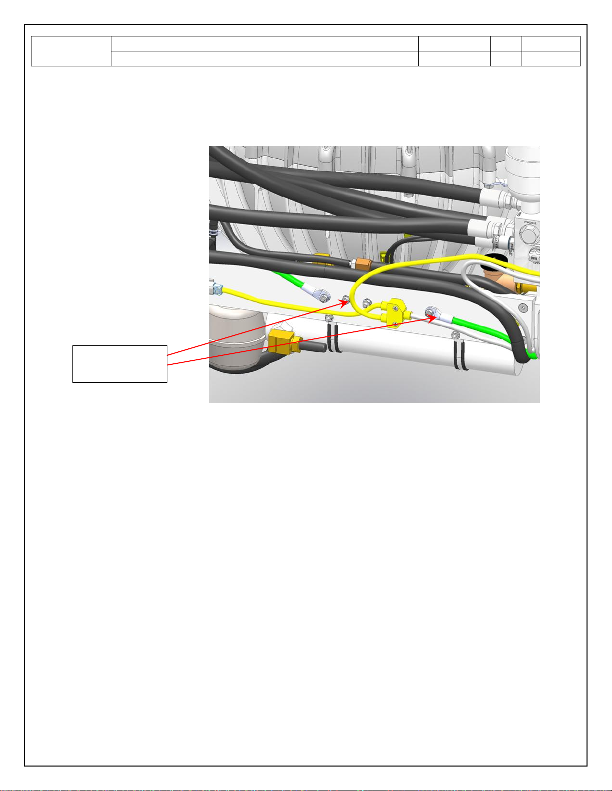
Inspect all hoses and fittings for damage / chafing –in the event a hose needs to be replaced,
contact Seakeeper Service Dept. for hose specifications and guidelines for replacing any cooling
hose.
Inspect bilge area under gyro for any indication of coolant leaks .