SealerSales W Series User manual

Pneumatic Pass Through Foot Sealers
WNC2-Series
Distributed By:
Version 1.0
Last Updated: 6/19/2020

1
Copyright © 2020 by Stephanie Hwang
All rights reserved. No part of this publication may be reproduced, distributed, or transmitted in any form or by any means, including photocopying,
recording, or other electronic or mechanical methods, without the prior written permission of the publisher, except in the case of brief quotations
embodied in critical reviews and certain other noncommercial uses permitted by copyright law. For permission requests, write to the publisher,
addressed “Attention: Permissions Coordinator,” at the address below.
Sealer Sales, Inc.
8820 Baird Avenue
Northridge, Ca 91324
www.sealersales.com
Printed in the United States of America

W N C 2 I N S T R U C T I O N M A N U A L
2
General Information
Thank you for purchasing our W-Series Pass Through Pneumatic Foot Sealers.
This owner’s manual contains information relating to your sealer. The manual will provide you
with basic information concerning both operation and maintenance of your new machine. Please
read it carefully as failure to do so may result in bodily injury and/or damage to the equipment.
Please fill in the information below. You will find the information on the machine identification
plate. You will need this information when ordering replacement parts or making technical
inquiries.
No part of this manual may be duplicated, reproduced, stored in a retrieval system, translated,
transcribed, or transmitted in any form without the express prior written permission of Sealer Sales.
E Q U I P M E N T I N F O R M A T I O N
Model #
Serial #
Purchase Date:
Reference # (found on packing slip)
Owner:

W N C 2 I N S T R U C T I O N M A N U A L
3
Safety Instructions
WARNING!
Below are general safety precautions and warnings that should be
understood prior to setting up or operating your equipment. Read and fully understand all instructions and
warnings prior to using this unit. Your safety is most important! Failure to comply with procedures may
result in serious injury or property damage. Remember:
Your personal safety is your
responsibility.
Unsafe practices or unauthorized modifications could result in accidents or property damage. Failure to
follow these safety rules and take necessary precautions can result in serious injury as well as damage to
equipment.
Never operate or service your sealer until you have read this manual completely and understand it
fully.
Plug the sealer into correct voltage wall outlet or surge protector.
Please ensure appropriate air supply (100-110psi) is available.
Do not use the sealer if the power cord, plug or any other parts are damaged. Be sure not to allow
the power cord to drape into your work area. Check that all parts are operating properly and
perform the intended functions. Check for any worn parts before starting operation. Check for all
other conditions that may affect the operation.
Reduce risk of unintentional starting. Make sure the power switch is in the "OFF" position before
connecting to the power source.
Always disconnect sealer from power source and air supply before servicing, changing accessories
or cleaning the unit.
To provide protection against the risk of electrical shock, the power connection must be properly
grounded at all times.
Do not leave the sealer unattended when in use. Disconnect the sealer from the power source
before leaving the work area.
Sealer is used solely for sealing thermoplastic materials. Using the machine for any other purpose
can cause damage to the machine and operator.
While operating machinery, wear close-fitting clothing and tie back long hair to prevent any
external items from getting caught in the machine. Do not wear jewelry when operating the sealer.

W N C 2 I N S T R U C T I O N M A N U A L
4
Never touch the heating elements with bare hand while the sealer is plugged into a power source,
in operation or just finished operation. Touching heated areas may cause fire and/or severe burns.
While machine is in operation, do not place fingers, tools, or other foreign objects on or into the
machine. Do not place hands or fingers near pinch points. Do not touch machine while it is in
operation. Perform all procedures carefully and watch where hands and fingers are at all times.
The sealer is not water resistant or water proof. Spraying down the machine will damage machine
or cause electrical shock. Do not submerge the sealer into water or liquid.
Do not operate sealer in a corrosive or humid environment.
Always keep the machine clean, lubricated and in good working condition. Follow any
maintenance and lubrication procedures outlined in this manual. Make sure unit is disconnected
from power source before cleaning.
NEVER use any accessories or parts from other manufacturers. Machine should not be altered or
modified using parts that are not genuine authorized parts. Doing so will VOID YOUR
WARRANTY.
When replacing the heating elements, always replace the PTFE adhesive under the
heating element. A worn PTFE adhesive can cause the heating element to break.
The
PTFE adhesive works as a barrier between the body of the sealer and the element. Never allow
the element to come in direct contact with the sealer's body as that will cause damage to the body
of the sealer and timer.
Never leave the sealer unattended. Be safe, disconnect the sealer from power source before
leaving work area.
Always keep out of reach of children and pets.
Close supervision is necessary when any appliance is near persons with reduced physical, sensory
or mental capabilities or lack of experience and knowledge . This sealer is NOT to be used by
children or by persons with reduced physical, sensory or mental capabilities or lack of experience
and knowledge.
DO NOT use the sealer outdoors.
DO NOT use the sealer while under the influence of drugs, medications or alcohol.
SAVE THESE INSTRUCTIONS - REFER TO THEM OFTEN AND USE THEM TO INSTRUCT OTHERS.

W N C 2 I N S T R U C T I O N M A N U A L
5
Introduction
W-Series WNC2 pass-through sealers are foot sealers ideal for high volume poly bag and other
thermoplastic sealing. The sealer allows you to keep both hands free for quicker and more accurate
sealing. Our W-Series sealers can seal polyethylene, polypropylene, saran, nylon, static shielding bags,
Mylar up to 20mil in total thickness. The open backed frame allows front to back pass through
capabilities
Features of the W-Series WNC2-Series Sealers
Your foot sealer is equipped with a wide range of standard features and capabilities.
Impulse sealing - no warm up time needed
Single or double impulse sealing
Available in wide variety of sealing lengths: 12", 18", 24", up to 40"
2.7mm, 5mm, or 10mm seal widths available
Work table included
Pneumatically operated - quieter than other sealers (air usage requirements 100PSI or 3-5CFM)
Better sealing pressure than manual sealers
Plug-in electronic timer for variable control of both sealing and congealing item
All metal construction
Heavy duty
Manufacturer spare parts kit includes: 2 heating elements
How Do W-Series Sealers Work?
Our W-Series WNC2-series impulse sealers fire a short burst of electricity through
a specially designed heating wire to weld thermoplastic materials together. The
length of the seal time will depend on the sealing characteristics of the bag being
sealed. The sealing process is simple: The operator places the bag between the
sealing jaws and presses the foot switch to activate the unit. The sealer is equipped
with a timer to adjust for sealing and cool settings. The seal process ends automatically once the preset
time is reached. The operator retrieves the sealed bag and repeats the process. Bags are sealed repeatedly
and uniformly.
Basic
Principles
Place material on lower
jaw and press foot
switch to activate
sealing process.
W N C 2 I N S T R U C T I O N M A N U A L
6
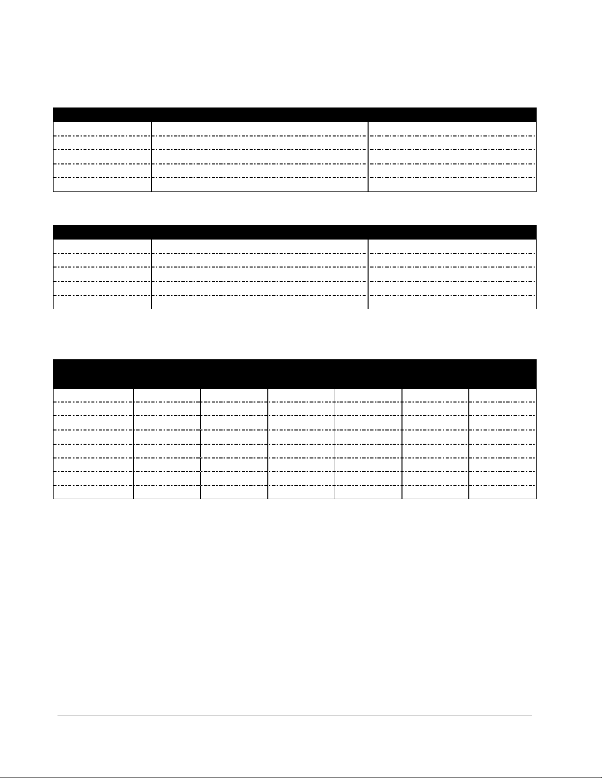
Single Impulse
Model #s
5mm Seal Width
10mm Seal Width
12" Seal Length
WNC2-305
WNC2-3010
18" Seal Length
WNC2-455
WNC2-4510
24" Seal Length
WNC2-605
WNC2-6010
30" Seal Length
WNC2-755
WNC2-7510
40" Seal Length
WNC2-1005
WNC2-1010
Double Impulse
Model #s
5mm Seal Width
10mm Seal Width
12" Seal Length
WNC2-305T
WNC2-3010T
18" Seal Length
WNC2-455T
WNC2-4510T
24" Seal Length
WNC2-605T
WNC2-6010T
30" Seal Length
WNC2-755T
WNC2-7510T
40" Seal Length
WNC2-1005T
WNC2-1010T
Model #s
Seal
Length
Seal
Width
Impulse
Voltage
Amps
Watts
WNC2-305
12"
5mm
Single
110V
8.5A
935W
WNC2-305T
12"
5mm
Double
110V
11A
1210W
WNC2-3010T
12"
10mm
Double
110V
34A
3740W
WNC2-455T
18"
5mm
Double
110V
28A
3080W
WNC2-4510T
18"
10mm
Double
110V
36A
3960W
WNC2-605T
24"
5mm
Double
110V
32A
3520W
WNC2-6010T
24"
10mm
Double
110V
40A
4400W
WNC2-755T
30"
5mm
Double
110V
46A
5060W

W N C 2 I N S T R U C T I O N M A N U A L
7
Electric Diagram - Double Impulse
W N C 2 I N S T R U C T I O N M A N U A L
8
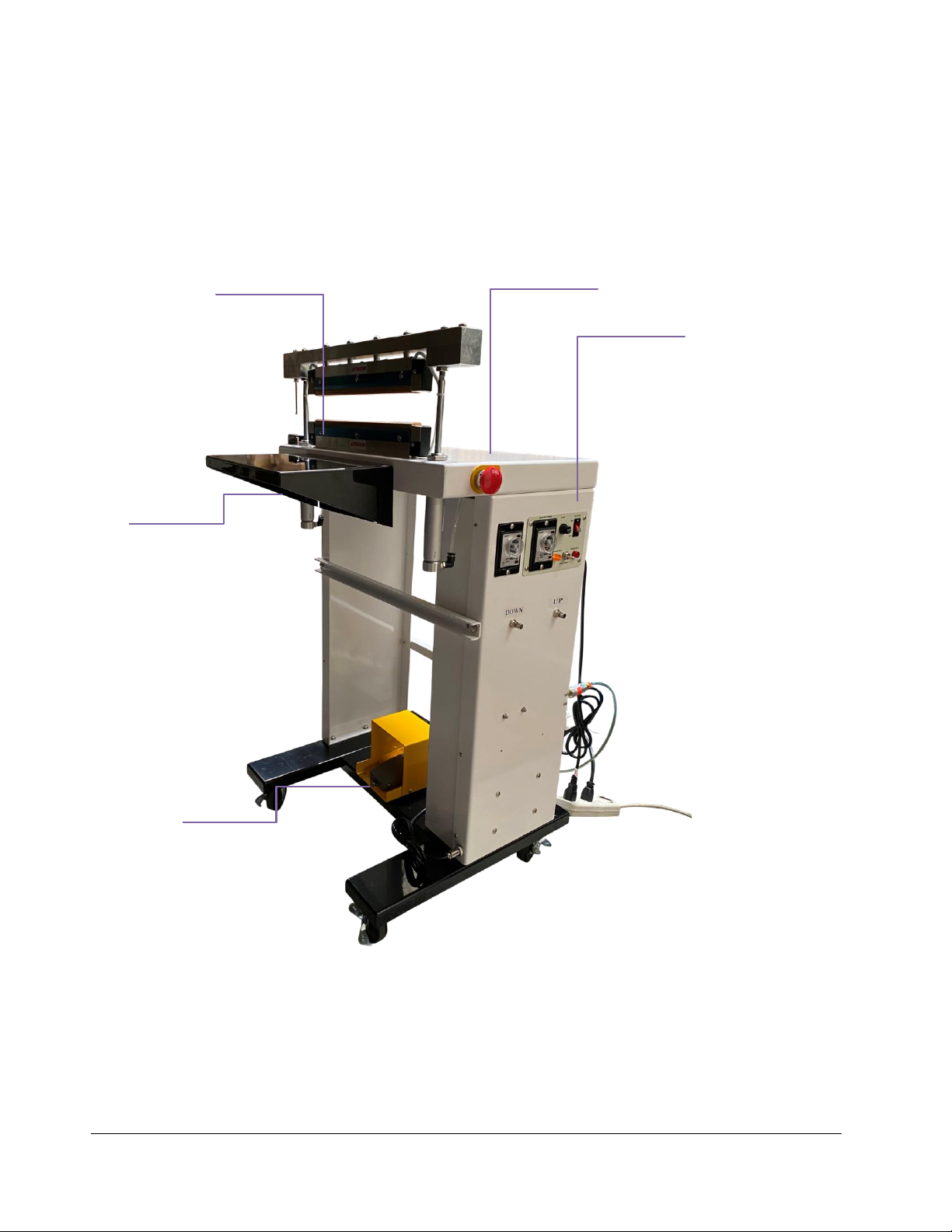
Getting to Know your Foot Sealer
W-Series Pneumatic Sealers are simple and efficient sealing machines.
Figure 1. Sealer Overview
Control Panel
Adjustable timer
for various
material
thicknesses
Seal time (0-2
seconds) and
cool timer
settings (0-6
seconds)
Foot Switch
Press down on foot
switch to activate sealing
process. Accompanied
with a foot protector
Seal Area
Place material to be
sealed on top of the
lower jaw
Working Table
Adjust work table height
as needed
Emergency Stop

W N C 2 I N S T R U C T I O N M A N U A L
9
Operating your Sealer
Important
Read this manual carefully, and make it available to everyone involved with the supervision, maintenance,
and/or operation of this machine. Additional copies are available at your request. (Contact your distributor
for this information.) Be very careful when operating, adjusting, or servicing this equipment. If in doubt, stop
and obtain qualified help before proceeding.
Installation
Place the sealer in the desired location with the required air and electrical power source available. (See power
requirements.) Make certain that proper electrical wiring is provided to guard against low voltage. If the
voltage is too low, the equipment will not function properly.
Finding the proper location is a most important function of the initial set-up. One must take several factors
into consideration:
Adequate power source
Access to compressed air set to 100-110 PSI, tubing and any fittings required to connect to the
compressed air. Please ask us about our compressed air kit.
Relationship to any conveyors necessary to remove finished product
Convenience of operator
1. Your new sealer comes wrapped on a pallet to protect it. If your machine does not arrive in this
condition, write on shipping paperwork that the box is damaged. Concealed damage may have occurred.
Figure 2. Sealer on Crate
W N C 2 I N S T R U C T I O N M A N U A L
10
2. In the package, your sealer will include
a. Operation manual
b. Sealer
c. One (1) heating element
d. One (1) Zone PTFE
e. Working table
f. Power Cord
g. Foot Switch
Assembly Instructions
1. Connect the foot switch to the sealer unit.
2. Connect the sealer to air source
a. The sealer will need air pressure at around 100PSI to work properly
b. When choosing a portable air compressor, choose one with a fifteen (15) gallon tank or
bigger. Some compressors are very loud, choose one that will give you best value
considering that the bigger the tank, the longer the air supply will last before the
compressor turns on.
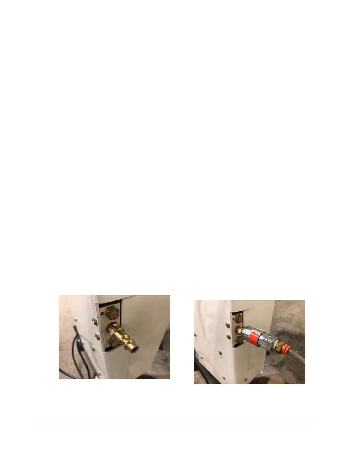
c. Install a 1/4" NPT plug to the back of the unit. Install your air tubing and hose
connection fittings to the installed 1/4" NPT plug. Our optional compressed air kit will
include 6ft tubing, coupler, and push to connect fitting.
Figure 3. 1/4" NPT fitting
Figure 4. Optional pneumatic kit includes tubing, coupler, and push to connect
fitting.

W N C 2 I N S T R U C T I O N M A N U A L
11
3. Connect the sealer to the power source. Standard 120 Volt A.C. outlet or 220-240 Volt A.C. if
your unit is made for this higher voltage. Look at the power cord tag to confirm the correct
voltage.
4. Install the working table to the sealer.
Operation
1. Before operating, check the heating element, PTFE cover, PTFE adhesive and the
silicone rubber.
2. Insert the power cord into the correct receptacle (110V).
3. Turn the power switch on.
4. Turn on the air compressor.
Figure 5. Control Panel
5. If your sealer is a double foot, select single or double impulse sealing using the switch selector.
Use double impulse sealing when sealing thicker materials
6. Set the SEALING knob to the lowest setting. Always start with a low setting and increase
gradually as needed. Thicker bags will need a higher setting.
7. Set the CONGEALING knob setting. The cooling (congeal) setting button determines the
congealing time for the sealing. For a high quality seal, seals must be able to cool under pressure.
We usually recommend a congeal setting of at least 2x that of the seal setting, but every
bag will have variations.
Thicker materials will require a longer cool (congealing) time.
8. Place material to be sealed on top of the lower jaw and press down on the foot switch. The
upper jaw will release when sealing process is complete.
Congeal Timer
Congeal should be at
least 2.5x sealtime
Seal Timer
Adjustable timer
for various
material
thicknesses
Seal time (0-2
seconds)
On/Off Switch
Single or Double Impulse Switch
Selector

W N C 2 I N S T R U C T I O N M A N U A L
12
Tips for Successful Sealing
1. If the seal is broken or damaged, decrease the sealing time.
2. If the seal is not fully welded, increase the sealing time.
3. If the sealing material sticks to the sealing pad, decrease the congealing time.
4. If the width of the seal is not perfect or does not match the size of the element, increase the
congealing time.
5. Always keep the sealer clean. Remove any residue found on the platform and PTFE cover. Silicone
spray may be used for this purpose.
6.
When replacing the heating elements, always replace the PTFE adhesive under
the heating element. A worn PTFE adhesive can cause the heating element to break.
The
PTFE adhesive works as a barrier between the body of the sealer and the element. Never allow the
element to come in direct contact with the sealer body as this will damage the timer.
7. Occasionally check the condition of the silicone rubber for wear or burns. A damaged silicone
rubber will affect the quality of the seal.
8. Be sure to turn off the power or unplug the unit before replacing any parts.
W N C 2 I N S T R U C T I O N M A N U A L
13
Maintenance
The following maintenance procedures should be followed to ensure the longevity of your W-Series
sealer.
Inspection and Cleaning
1. Inspect your machine daily.
2. Use a clean cloth to remove any plastic residue remaining on the PTFE cloth.
3. When replacing the elements, always check the condition of the bottom PTFE tape.
4. Check the condition of the silicone rubber for wear and burns. A damaged silicone rubber will
affect the quality of the seal.
Replacement Kit Instructions
Our impulse sealers will require new heating elements and PTFE from time to time. Heating elements will
break through wear and tear. A good rule of thumb is to replace the PTFE adhesive every time you change
your heating element. The PTFE cover prevents the plastic or other thermoplastic material you are sealing
from sticking to the heating element.
Replacement kits are available from your distributor. Kits include (2) heating elements, (2) 1/2" 6mil PTFE
adhesives, and (2) 3" 5mil PTFE covers.
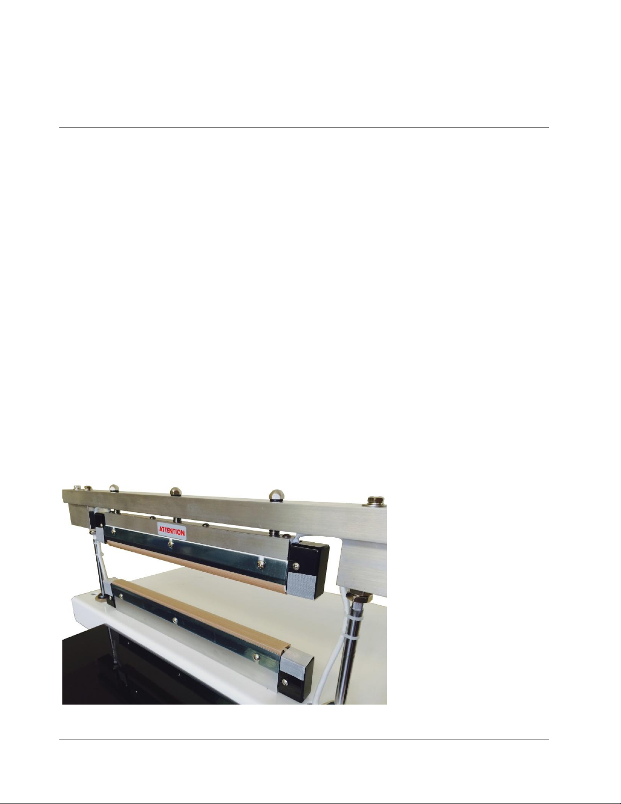
Figure 6. Consumable Parts on WNC2 sealer
Upper Seal Bar
•SiliconeRubber
•PTFETape – ½” x 6mil
•Heating Element
•PTFECloth – 3” x 5mil
LowerSeal Bar
•Fiber Plate (WHLH-49)
•PTFE Tape – ½” x 6mil
•Heating Element
•PTFECloth – 3” x 5mil

W N C 2 I N S T R U C T I O N M A N U A L
14
To install your replacement kit on your sealer, turn off power and unplug sealer.
Removing Worn Parts.
1. Loosen the screws on the PTFE cover plate.
2. Remove the terminal assembly block cover.
Figure 7. Loosen screws on PTFE plate.
Figure 8. Remove heating element cover.
3. Lift up the PTFE cover to expose the heating element.
4. Remove the heating element by unscrewing the element screw (apply pressure to the heating
element with your finger while unscrewing the screw to prevent heating element from twisting.)
5. Peel off the PTFE adhesive under the heating element.
Installing New Replacement Parts.
1. Remove the backing of the liner found on the PTFE adhesive.
2. Apply it to the sealer’s sealing platform. The PTFE adhesive must always extend past the sealing
platform by approximately ¼” to ½” on both ends. Bend down the excess on both ends. (The
PTFE adhesive acts a barrier between the metal body and the heating element. Never allow the
heating element to come in direct contact with the sealer’s body because it will damage the timer.)
3. Place a new element on top of the PTFE adhesive by screwing the element in the heating terminal
assembly block. To attach the element to the other side, lift the latch found on the heating
terminal assembly block to push the block inward and securely screw the element to the block.
Check the element to ensure it is tight and intact.

W N C 2 I N S T R U C T I O N M A N U A L
15
Figure 9. Screw element in place.
Figure 10.Lift latch on heating block to secure element in place.
4. Replace worn PTFE cover and tighten the screws to affix to the PTFE cover plate.

W N C 2 I N S T R U C T I O N M A N U A L
16
Troubleshooting
Problem Possible Causes Solution
No sealing
Timer lights off
1. Disconnected power cord
2. Power cord is broken
3. Blown fuse
4. Transformer needs replacement
5. Timer needs replacement
1. Check or change plug
2. Replace power cord
3. Replace fuse
4. Replace the transformer
5. Replace timer
No sealing
Timer lights are on
1. Heating element is broken
2. Poor contact at heating terminal
blocks
1. Replace the heating element
2. Clean, tighten or change the heating terminal
blocks
No sealing
Upper jaw does not move
1. Foot switch malfunction
2. Air connection
1. Replace foot switch
2. Check air connection
Burnt PTFE cloth
1. Timer malfunction
2. Timer setting too high
1. Replace timer
2. Decrease timer setting
Broken heating element 1. Worn PTFE adhesive 1. Replace PTFE adhesive
Wrinkled seal
1. Seal time is set too high
2. Cooling (congeal) time is too
short
1. Decrease seal time
2. Increase congealing time
Imperfect seal
1. Worn PTFE cover
2. Worn silicone rubber
1. Replace PTFE cover
2. Replace the silicone rubber
Burnt seal 1. Seal time is set too high 1. Decrease seal time
No seal 1. Seal time is set too low 1. Increase seal time
Seal sticking to PTFE cover
1. Worn or dirty PTFE cover
2. Worn or dirty silicone rubber
1. Replace or clean PTFE cover
2. Replace or clean silicone rubber
Other manuals for W Series
1
This manual suits for next models
1
Table of contents
Other SealerSales Food Saver manuals

SealerSales
SealerSales FRM-1120LD User manual

SealerSales
SealerSales GWSZ-300 User manual

SealerSales
SealerSales OnPak Gen 3.0 User manual

SealerSales
SealerSales FKR-200A User manual

SealerSales
SealerSales SS Series User manual

SealerSales
SealerSales FRM-1120 Series User manual

SealerSales
SealerSales CBS-880 Series User manual

SealerSales
SealerSales Impresse FRM-1010 User manual

SealerSales
SealerSales WD-305HT User manual

SealerSales
SealerSales W-300DAT User manual


