Optional Items
Depending upon your application, you are likely to find one or more of the following items useful for
interfacing the SeaLINK+4.VC. All items can be purchased from our website (http://www.sealevel.com/) or
by calling 864-843-4343.
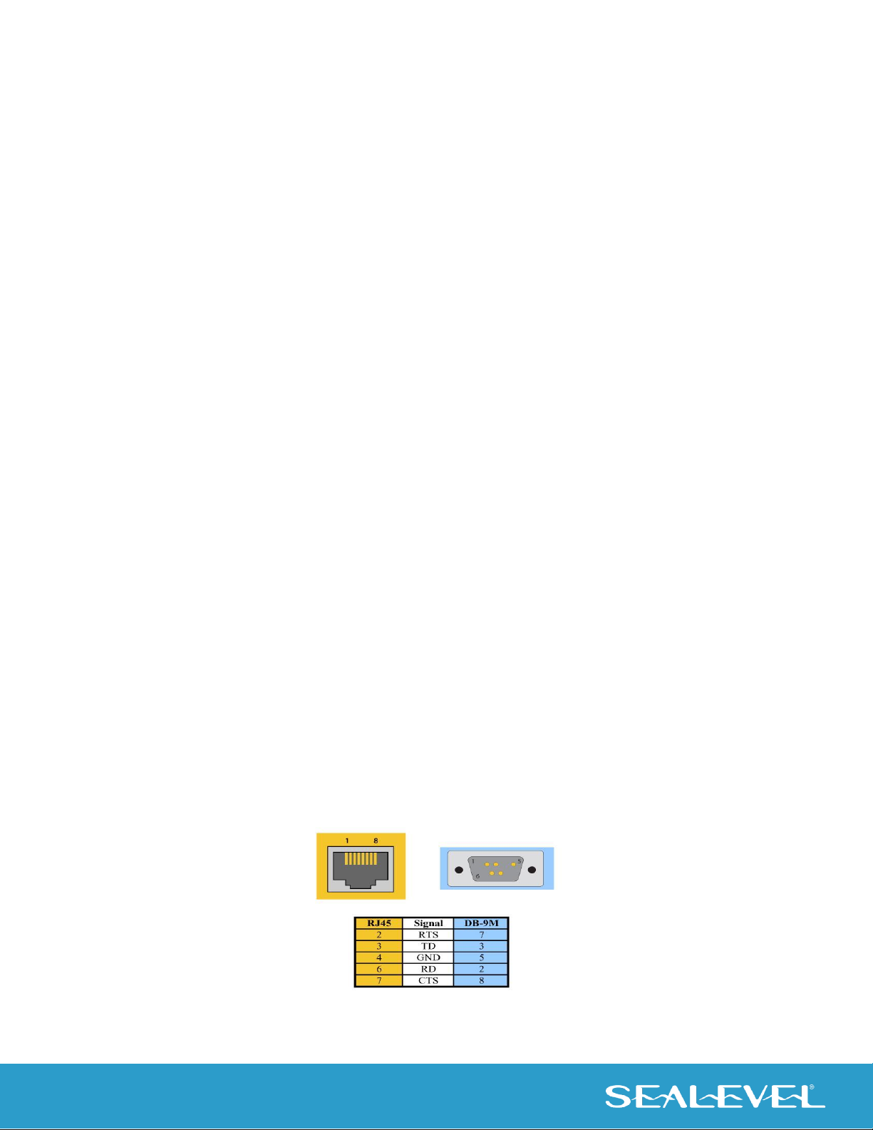
•DB9 Male to RJ45 Modular Adapter (Item# RJ9P-232)
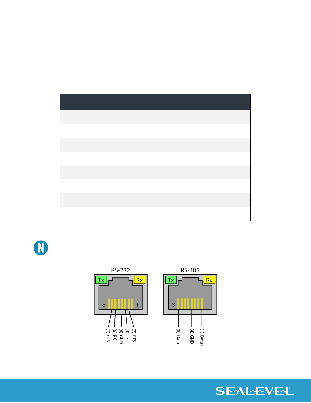
Preconfigured for use with the SeaLINK+4.VC, this modular adapter converts the RJ45 RS-232 pinout
from the SeaLINK+4.VC to a DB9 male RS-232 serial port. Standard CAT5 patch cables can be used to
extend the serial port up to 50 feet away from the SeaLINK+4.VC.
•DB25 Male to RJ45 Modular Adapter (Item# RJ25P-232)
Preconfigured for use with the SeaLINK+4.VC, this modular adapter converts the RJ45 RS-232 pinout
from the SeaLINK+4.VC to a DB25 male RS-232 serial port. Standard CAT5 patch cables can be used
to extend the serial port up to 50 feet away from the SeaLINL+16.VC.
•DB9 Male to RJ45 Modular Adapter (Item# RJ9P8)
The RJ9P8 includes an RJ45 connector and converts it to a DB9 Male connector, which allows the use
of standard twisted pair cabling. The RJ9P8 ships unassembled and can be configured for virtually any
pin out.
•DB25 Male to RJ45 Modular Adapter (Item# RJ25P8)
The RJ25P8 includes an RJ45 connector and converts it to a DB25 Male connector, which allows the
use of standard twisted pair cabling. The RJ25P8 ships unassembled and can be configured for
virtually any pin out.
•USB ‘A’ to ‘A’ Extension Cable, 3 Meters in Length (Item# CA214)
The CA214 is a fully rated USB extension cable that allows adding 3 meters (USB maximum of 5 meters)
to any existing USB cable. The cable has a type ‘A’ male connector on one end and a type ‘A’ female
connector on the other end.
•RJ45 Patch Cable, 7’ in Length (Item# CA246)
Standard 7’ CAT5 patch cable with one-to-one pinout.
•RJ45 Patch Cable, 10’ in Length (Item# CA247)
Standard 10’ CAT5 patch cable with one-to-one pinout.