SeaLevel COMM+8 User manual

1
© Sealevel Systems, Inc. 3420 Manual | SL9145 9/2022
COMM+8
™
User Manual | 3420

2
© Sealevel Systems, Inc. 3420 Manual | SL9145 9/2022
Contents
CONTENTS...........................................................................................................................................................2
INTRODUCTION ................................................................................................................................................... 3
BEFORE YOU GET STARTED ...............................................................................................................................4
CARD SETUP ........................................................................................................................................................7
INSTALLATION ..................................................................................................................................................11
TECHNICAL DESCRIPTION ...............................................................................................................................13
SPECIFICATIONS ...............................................................................................................................................16
APPENDIX A – TROUBLESHOOTING................................................................................................................17
APPENDIX B – HOW TO GET ASSISTANCE .....................................................................................................18
APPENDIX C – ELECTRICAL INTERFACE ........................................................................................................19
APPENDIX D – ASYNCHRONOUS COMMUNICATIONS ..................................................................................20
APPENDIX E – SILK SCREEN ............................................................................................................................21
APPENDIX F – COMPLIANCE NOTICES...........................................................................................................22
WARRANTY ........................................................................................................................................................23

3
© Sealevel Systems, Inc. 3420 Manual | SL9145 9/2022
Introduction
Overview
The Sealevel Systems COMM+8 provides the PC with eight RS-232 asynchronous ports. The COMM+8
allows for connection to any device utilizing the RS-232 electrical interface, such as modems, data-entry
terminals, and plotters.

4
© Sealevel Systems, Inc. 3420 Manual | SL9145 9/2022
Before You Get Started
What’s Included
The COMM+8 is shipped with the following items. If any of these items is missing or damaged, contact the
supplier.
•COMM+8 Serial I/O Adapter
•“Octopus” Cable providing 8 DB-25 or DB-9 connectors
Advisory Conventions
Warning
The highest level of importance used to stress a condition where damage could result to the
product, or the user could suffer serious injury.
Important
The middle level of importance used to highlight information that might not seem obvious or a
situation that could cause the product to fail.
Note
The lowest level of importance used to provide background information, additional tips, or other
non-critical facts that will not affect the use of the product.

5
© Sealevel Systems, Inc. 3420 Manual | SL9145 9/2022
Factory Default Settings
The COMM+8 factory default settings are as follows:
Port # Base Address IRQ E12
Port 1 280 5 DIV4
Port 2 288 5
Port 3 290 5
Port 4 298 5
Port 5 2A0 5
Port 6 2A8 5
Port 7 2B0 5
Port 8 2B8 5
To install the COMM+8 using factory default settings, refer to the Installation section of this manual.
For your reference, record installed COMM+8 settings below:
Port # Base Address IRQ E12
Port 1
Port 2
Port 3
Port 4
Port 5
Port 6
Port 7
Port 8

6
© Sealevel Systems, Inc. 3420 Manual | SL9145 9/2022
The following table illustrates the port assignments for the Factory Default setting.
Port # DB-25# Address Example
1 1 Base+0 280-287
2 2 Base+8 288-28F
3 3 Base+16 290-297
4 4 Base+24 298-29F
5 5 Base+32 2A0-2A7
6 6 Base+40 2A8-2AF
7 7 Base+48 2B0-2B7
8 8 Base+56 2B8-2BF

7
© Sealevel Systems, Inc. 3420 Manual | SL9145 9/2022
Card Setup
The COMM+8 contains several jumper straps that must be set for proper operation.
Address Selection
The COMM+8 occupies 64 I/O locations and can be addressed two different ways. If header E11 is set to
the “Switch” position the COMM+8 occupies 64 consecutive I/O locations, and the DIP-switch is used to
set the base address for these locations. The starting address for these 64 I/O locations must be on a 64-
byte boundary i.e.: Hex 200, 240, 280, or 2C0. Be careful when selecting the base address as some
selections conflict with existing PC ports. The following table shows several examples that usually do not
cause a conflict. Refer to Appendix A for common address contentions.
Address
Switch Position Setting:
1
2
3
4
5
6
7
100-13F
On
On
On
On
Off
On
On
180-1BF
On
On
On
On
Off
Off
On
240-27F
On
On
On
Off
On
On
Off
280-2BF
On
On
On
Off
On
Off
On
2C0-2FF
On
On
On
Off
On
Off
Off
300-3FF
On
On
On
Off
Off
On
On
500-53F
On
On
Off
On
Off
On
On
580-5BF
On
On
Off
On
Off
Off
On
1500-153F
Off
On
Off
On
Off
On
On
1580-15BF
Off
On
Off
On
Off
Off
On
Figure 1 - Address Selection Table
The following illustration shows the correlation between the DIP-switch setting and the address bits used
to determine the base address. In the example below, address 280 (Factory Default) is selected as a base.
ON
OFF
1 2 3 4 5 6 7
A12 A6
Figure 2 - DIP-switch Illustration
Setting the switch “On” or “Closed” corresponds to a “0” in the address, while leaving it “Off” or
“Open” corresponds to a “1”.

8
© Sealevel Systems, Inc. 3420 Manual | SL9145 9/2022
“PAL” Addressing
If header E11 is set to the “PAL” position, the board can be addressed at a customized location. Using the
“PAL” option will allow you to obtain COM1: - COM4: addresses, XENIX COM: addresses, or any other
standard or nonstandard address configuration. Using the “PAL” feature is a very cost-effective means of
solving complex addressing problems. For more information on implementing the “PAL” option, please
contact Sealevel Systems Technical Support.
IRQ Selection
Each port on the COMM+8 has an interrupt jumper that may have to be set prior to use. The software you
are using with the board will determine which interrupts, if any are to be used. The DOS serial port interface
software does not use interrupts, while interrupt buffer programs do. DOS does not require the interrupt to
be set, while most Multi - User Operating Systems will. Consult the particular manual for the software that
you are using to determine the proper setting.
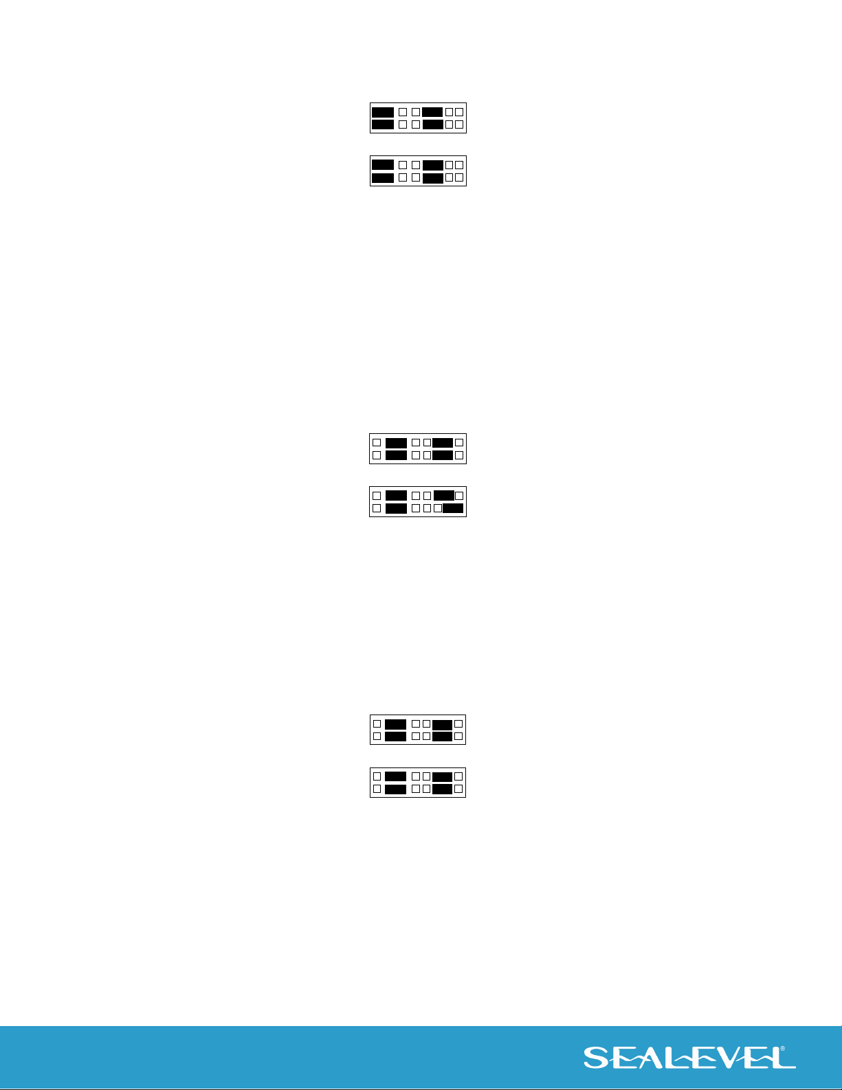
To set the interrupt for a particular port, first select the header for the port desired. Headers E1-E8
correspond to Ports 1-8. Next select an IRQ by placing one of the jumpers on the header location that
corresponds to the IRQ number that you wish to use. Below is an example of a selected IRQ.
Figure 3 - Headers E1 to E8 (IRQ15 selected)
Interrupt Mode Options
The COMM+8 will allow each port to have an independent interrupt level or share an interrupt with another
port on the adapter. The COMM+8 will even share interrupts with a compatible port that is located on
another adapter. The COMM+8 can operate in three interrupt modes. Header E9 determines the interrupt
mode for Ports 1-4 and header E10 determines the interrupt mode for ports 5-8.
“N” indicates the (N)ormal, single interrupt per port mode. “S” Indicates the (S)hared interrupt mode, which
allows more than one port to access a single IRQ. Any two or more ports can share a common IRQ by
placing the jumpers on the same IRQ setting and setting the appropriate selections at E1-E8. Consult your
particular software for IRQ selection. If no interrupt is desired, remove the jumper. “M” indicates the
inclusion of a 1K ohm pull-down resistor required on one port when sharing interrupts.

9
© Sealevel Systems, Inc. 3420 Manual | SL9145 9/2022
1
2
3
4
5
6
7
8
N S M
N S M
E9
E10
Figure 4 - Header E9 and E10, Normal IRQ Mode
Set jumpers to “S” for shared interrupt mode on all blocks sharing an IRQ except one. Set that port block
for “M”. This provides the pull-down resistor circuit that makes IRQ sharing possible. If you are using more
than one COMM+8 or a compatible adapter in a bus, you should only have one port set to “M”. The following
example shows all eight ports sharing a single IRQ.
1
2
3
4
5
6
7
8
N S M
N S M
E9
E10
Figure 5 - Header E9 and E10, Shared IRQ Mode
Set all jumpers to “S” if you are using more than one COMM+8 in a bus or you wish to completely remove
the pull-down resistor for hardware compatibility. Setting the COMM+8 in this configuration when it is not
accompanied by a pull-down resistor will prevent the ports from triggering an interrupt.
1
2
3
4
5
6
7
8
N S M
N S M
E9
E10
Figure 6 - Header E9 and E10, Sharing IRQs with another adapter

10
© Sealevel Systems, Inc. 3420 Manual | SL9145 9/2022
Clock Modes
The COMM+8 employs a unique clocking option that allows the user to select from divide by 4 or divide by
1 clocking modes. This mode is selected at E12.
To select the Baud rates commonly associated with COM: ports (i.e., 2400, 4800, 9600, 19.2, … 115.2K Bps)
place the jumper in the divide by 4 mode (silk-screen DIV4).
DIV1
DIV4
Figure 7 - Clocking Mode ‘Divide By 4’
To select the maximum data rate (460.8K bps) place the jumper in the divide by 1 (silk-screen DIV1) position.
DIV1
DIV4
Figure 8 - Clocking Mode ‘Divide By 1’
Baud Rates and Divisors for the ‘Div1’ mode
The following table shows some common data rates and the matching data rates you should choose if
using the adapter in the ‘Div1’ mode.
For this Data Rate Choose this Data Rate
1200 bps 300 bps
2400 bps 600 bps
4800 bps 1200 bps
9600 bps 2400 bps
19.2K bps 4800 bps
57.6 K bps 14.4K bps
115.2 K bps 28.8K bps
230.4K bps 57.6 K bps
460.8K bps 115.2 K bps

11
© Sealevel Systems, Inc. 3420 Manual | SL9145 9/2022
If your communications package allows the use of Baud rate divisors, choose the appropriate divisor from
the following table:
For this Data Rate Choose this Divisor
1200 bps 384
2400 bps 192
4800 bps 96
9600 bps 48
19.2K bps 24
38.4K bps 12
57.6K bps 8
115.2K bps 4
230.4K bps 2
460.8K bps 1
Installation
Software Installation
Windows Installation
Do not install the Adapter in the machine until the software has been fully installed.
Only users running Windows 7 or newer should utilize these instructions for accessing and
installing the appropriate driver via Sealevel’s website. If you are utilizing an operating system
prior to Windows 7, please contact Sealevel by calling 864.843.4343 or emailing
instructions.
1. Begin by locating, selecting, and installing the correct software from the Sealevel
software driver database.
2. Select the Part Number (3420) for your device from the listing.
3. Click the ‘Download Now’ button for SeaCOM for Windows.

12
© Sealevel Systems, Inc. 3420 Manual | SL9145 9/2022
4. The setup file will automatically detect the operating environment and install the
proper components.
To confirm that the SeaCOM driver has been successfully installed, click on the ‘Start’ button, and then
select ‘All Programs’. You should see the ‘SeaCOM’ program folder listed.
You are now ready to proceed with connecting the 3420 to your system. Refer to the Hardware
Installation section for details.
Other Operating Systems
Refer to the appropriate section of the Serial Utilities Software.
For additional software support, including QNX, please call Sealevel Systems’ Technical Support, (864) 843-
4343. Our technical support is free and available from 8:00 AM - 5:00 PM Eastern Time, Monday through
Friday. For email support contact: support@sealevel.com.
System Installation
The COMM+8 can be installed in any 16-bit PC expansion slot. The COMM+8 contains several jumper straps
for each port that must be set for proper operation prior to installing the COMM+8 into the computer.
1. Turn off PC power. Disconnect the power cord.
2. Remove the PC case cover.
3. Locate an available slot and remove the blank metal slot cover.
4. Gently insert the COMM+8 into the slot. Make sure that the adapter is seated properly.
5. Replace the screw.
6. Install the “Octopus” Cable
7. Replace the cover.
8. Connect the power cord.
Installation is complete.

13
© Sealevel Systems, Inc. 3420 Manual | SL9145 9/2022
Technical Description
The Sealevel COMM+8 provides 8 additional serial ports for terminals, modems, printers, etc. The COMM+8
utilizes the 16554 UART chip. This chip features programmable baud rate, data format, interrupt control
and a 16-byte FIFO.
Features
•Eight RS-232 Ports with full modem control signals
•“PAL” addressing option allowing “Turn Key” configurations
•Selectable/Sharable Interrupts (IRQs 2/9-7,10,11,12, & 15 )
•8 DB-9 or DB-25 male connectors provided using the Sealevel Systems “Octopus Cable”
Interrupt Status Port
The COMM+8 provides the user with an Interrupt Status Port (ISP) for greater throughput when servicing
multiple ports on a single interrupt line. The ISP is a read only 8-bit register that sets a corresponding bit
when an interrupt is pending. Port 1 interrupt line corresponds with Bit D0 of the status port, Port 2 with D1
etc.
The ISP can be addressed two different ways. If header E11 is in the “Switch” position the Status Register
is located at Base+7 on each port (Example: Base = 280 Hex, Status Port = 287, 28F… etc.). This allows any
one of eight locations to be read to obtain the value in the status register. All eight status ports on the
COMM+8 are identical, so any one of the eight can be read. If header E11 is in the “PAL” position, the status
port can be addressed at any location. Please contact Sealevel Systems for information on PAL
programming and custom configurations.
Example: This indicates that Channel 2 has an interrupt pending.
Bit Position:
7
6
5
4
3
2
1
0
Value Read:
0
0
0
0
0
0
1
0

14
© Sealevel Systems, Inc. 3420 Manual | SL9145 9/2022
DB-25 Connector Pin Assignments (DB-25 Male)
Signal Name Pin # Mode
GND Ground 7
TD Transmit Data 2 Output
RTS Request To Send 4 Output
DTR Data Terminal Ready 20 Output
RD Receive Data 3 Input
CTS Clear To Send 5 Input
DSR Data Set Ready 6 Input
DCD Data Carrier Detect 8 Input
RI Ring Indicator 22 Input
Figure 9 - DB-25 Connector Pin Assignments
DB-9 (EIA-574 DTE) (DB-9 Male)
Signal Name Pin # Mode
GND Ground 5
TD Transmit Data 3 Output
RTS Request To Send 7 Output
DTR Data Terminal Ready 4 Output
RD Receive Data 2 Input
CTS Clear To Send 8 Input
DSR Data Set Ready 6 Input
DCD Data Carrier Detect 1 Input
RI Ring Indicator 9 Input
Figure 10 - DB-9 Connector Pin Assignments

15
© Sealevel Systems, Inc. 3420 Manual | SL9145 9/2022
DB-78 Connector Pin Assignments (DB-78 Female)
Port # 12345678
TD 36 12 27 3 75 51 66 42
RD 37 11 28 2 76 50 67 41
RTS 17 31 8 22 56 70 47 61
CTS 16 32 7 23 55 71 46 62
DTR 35 13 26 4 74 52 65 43
DSR 18 30 9 21 57 69 48 60
DCD 38 10 29 1 77 49 68 40
RI 15 33 6 24 54 72 45 63
GND 34 14 25 5 73 53 64 44
Figure 11 - DB-78 Connector Pin Assignments
Please terminate any control signals that are not going to be used. The most common way to do
this is connect RTS to CTS and RI. Also, connect DCD to DTR and DSR. Terminating these pins, if
not used, will help insure you get the best performance from your adapter.

16
© Sealevel Systems, Inc. 3420 Manual | SL9145 9/2022
Specifications
Environmental Specifications
Specification Operating Storage
Temperature Range 0º to 50º C (32º to 122º F) -20º to 70º C (-4º to 158º F)
Humidity Range 10 to 90% R.H. Non-Condensing 10 to 90% R.H. Non-Condensing
Power Consumption
Supply line +12 VDC -12 VDC +5 VDC
Rating 110 mA 130 mA 320 mA
Mean Time Between Failures (MTBF)
Greater than 150,000 hours. (Calculated)
Physical Dimensions
Board length 7.0 inches (17.78 cm)
Board height including Goldfingers 4.2 inches (10.66 cm)
Board height excluding Goldfingers 3.9 inches (9.91 cm)

17
© Sealevel Systems, Inc. 3420 Manual | SL9145 9/2022
Appendix A – Troubleshooting
The adapter should provide years of trouble-free service. However, in the event that device appears to not
be functioning incorrectly, the following tips can eliminate most common problems without the need to call
Technical Support.
1. Identify all I/O adapters currently installed in your system. This includes your on-board serial ports,
controller cards, sound cards etc. The I/O addresses used by these adapters, as well as the IRQ (if
any) should be identified.
2. Configure your Sealevel Systems adapter so that there is no conflict with currently installed
adapters. No two adapters can occupy the same I/O address.
3. Make sure the Sealevel Systems adapter is using a unique IRQ The IRQ is typically selected via an
on-board header block. Refer to the section on Card Setup for help in choosing an I/O address and
IRQ.
4. Make sure the Sealevel Systems adapter is securely installed in a motherboard slot.
5. If you are utilizing an operating system prior to Windows 7, please contact Sealevel by calling (864)
843-4343 or emailing support@sealevel.com to receive more information in regard to the utility
software which will determine if your product is functioning properly.
6. Only users running Windows 7 or newer should utilize the diagnostic tool ‘WinSSD’ installed in the
SeaCOM folder on the Start Menu during the setup process. First find the ports using the Device
Manager, then use ‘WinSSD’ to verify that the ports are functional.
7. Always use the Sealevel Systems diagnostic software when troubleshooting a problem. This will
help eliminate any software issues and identify any hardware conflicts.
8. The following are known I/O conflicts:
•The 278 and 378 settings may conflict with your printer I/O adapter.
•3B0 cannot be used if a Monochrome adapter is installed.
•3F8-3FF is typically reserved for COM1:
•2F8-2FF is typically reserved for COM2:
•3E8-3EF is typically reserved for COM3:
•2E8-2EF is typically reserved for COM4:
If these steps do not solve your problem, please call Sealevel Systems’ Technical Support, (864) 843-4343.
Our technical support is free and available from 8:00 A.M.- 5:00 P.M., Eastern Time Monday through Friday.
For email support contact support@sealevel.com.

18
© Sealevel Systems, Inc. 3420 Manual | SL9145 9/2022
Appendix B – How To Get Assistance
Please refer to Troubleshooting Guide prior to calling Technical Support.
1. Begin by reading through the Trouble Shooting Guide in Appendix A. If assistance is still needed,
please see below.
2. When calling for technical assistance, please have your user manual and current adapter settings.
If possible, please have the adapter installed in a computer ready to run diagnostics.
3. Sealevel Systems provides an FAQ section on its web site. Please refer to this to answer many
common questions. This section can be found at http://www.sealevel.com/faq.asp.
4. Sealevel Systems maintains a web page on the Internet. Our home page address is
www.sealevel.com. The latest software updates, and newest manuals are available via our web
site.
5. Technical support is available Monday to Friday from 8:00 A.M. to 5:00 P.M. Eastern Time.
Technical support can be reached at (864) 843-4343. For email support contact
support@sealevel.com.
RETURN AUTHORIZATION MUST BE OBTAINED FROM SEALEVEL SYSTEMS BEFORE RETURNED
MERCHANDISE WILL BE ACCEPTED. AUTHORIZATION CAN BE OBTAINED BY CALLING SEALEVEL
SYSTEMS AND REQUESTING A RETURN MERCHANDISE AUTHORIZATION (RMA) NUMBER.

19
© Sealevel Systems, Inc. 3420 Manual | SL9145 9/2022
Appendix C – Electrical Interface
RS-232
Quite possibly the most widely used communication standard is RS-232. This implementation has been
defined and revised several times and is often referred to as RS-232-C/D/E or EIA/TIA-232-C/D/E. It is
defined as “Interface between Data Terminal Equipment and Data Circuit- Terminating Equipment Employing
Serial Binary Data Interchange” The mechanical implementation of RS-232 is on a 25 pin D sub connector.
The IBM PC computer defined the RS-232 port on a 9 pin D sub connector and subsequently the EIA/TIA
approved this implementation as the EIA/TIA-574 standard. This standard has defined as the “9-Position
Non-Synchronous Interface between Data Terminal Equipment and Data Circuit-Terminating Equipment
Employing Serial Binary Data Interchange”. Both implementations are in widespread use and will be referred
to as RS-232 in this document. RS-232 is capable of operating at data rates up to 20 Kbps / 50 ft. The
absolute maximum data rate may vary due to line conditions and cable lengths. RS-232 often operates at
38.4 Kbps over very short distances. The voltage levels defined by RS-232 range from -12 to +12 volts. RS-
232 is a single ended or unbalanced interface, meaning that a single electrical signal is compared to a
common signal (ground) to determine binary logic states. A voltage of +12 volts (usually +3 to +10 volts)
represents a binary 0 (space) and -12 volts (-3 to -10 volts) denotes a binary 1 (mark). The RS-232 and the
EIA/TIA-574 specification define two types of interface circuits Data Terminal Equipment (DTE) and Data
Circuit-Terminating Equipment (DCE). The Sealevel Systems Adapter is a DTE interface.

20
© Sealevel Systems, Inc. 3420 Manual | SL9145 9/2022
Appendix D – Asynchronous Communications
Serial data communications implies that individual bits of a character are transmitted consecutively to a
receiver that assembles the bits back into a character. Data rate, error checking, handshaking, and
character framing (start/stop bits) are pre-defined and must correspond at both the transmitting and
receiving ends.
Asynchronous communications is the standard means of serial data communication for PC compatibles
and PS/2 computers. The original PC was equipped with a communication or COM: port that was designed
around an 8250 Universal Asynchronous Receiver Transmitter (UART). This device allows asynchronous
serial data to be transferred through a simple and straightforward programming interface. A start bit,
followed by a pre-defined number of data bits (5, 6, 7, or 8) defines character boundaries for asynchronous
communications. The end of the character is defined by the transmission of a pre-defined number of stop
bits (usually 1, 1.5 or 2). An extra bit used for error detection is often appended before the stop bits.
Figure12 - Asynchronous Communications Bit Diagram
This special bit is called the parity bit. Parity is a simple method of determining if a data bit has been lost
or corrupted during transmission. There are several methods for implementing a parity check to guard
against data corruption. Common methods are called (E)ven Parity or (O)dd Parity. Sometimes parity is not
used to detect errors on the data stream. This is referred to as (N)o parity. Because each bit in
asynchronous communications is sent consecutively, it is easy to generalize asynchronous
communications by stating that each character is wrapped (framed) by pre-defined bits to mark the
beginning and end of the serial transmission of the character. The data rate and communication
parameters for asynchronous communications have to be the same at both the transmitting and receiving
ends. The communication parameters are baud rate, parity, number of data bits per character, and stop bits
(i.e.,9600,N,8,1).
This manual suits for next models
1
Table of contents
Other SeaLevel Recording Equipment manuals

SeaLevel
SeaLevel DIO-104.OPTO User manual

SeaLevel
SeaLevel COMM+8.LPCI User manual

SeaLevel
SeaLevel ACB-188 User manual

SeaLevel
SeaLevel PC-SIO-232 User manual

SeaLevel
SeaLevel SeaLINK PIO-96 User manual

SeaLevel
SeaLevel PLC-16.PCI User manual

SeaLevel
SeaLevel SeaLINK+4.VC User manual

SeaLevel
SeaLevel COMM+8.LPCI User manual

SeaLevel
SeaLevel PC-SIO-850 User manual

SeaLevel
SeaLevel 5402e User manual