SeaLevel 5402e User manual

1
© Sealevel Systems, Inc. 5402e Manual | SL9233 8/2021
ACB-MP+4.PCIe Synchronous Serial
Interface
User Manual | 5402e

2
© Sealevel Systems, Inc. 5402e Manual | SL9233 8/2021
Contents
CONTENTS...........................................................................................................................................................2
INTRODUCTION ...................................................................................................................................................3
BEFORE YOU GET STARTED ...............................................................................................................................4
INSTALLATION & CONFIGURATION...................................................................................................................6
HARDWARE INSTALLATION ............................................................................................................................... 7
TECHNICAL DESCRIPTION .................................................................................................................................8
TECHNICAL SPECIFICATIONS..........................................................................................................................15
APPENDIX A –HANDLING INSTRUCTIONS ....................................................................................................16
APPENDIX B –TROUBLESHOOTING................................................................................................................17
APPENDIX C –ELECTRICAL INTERFACE ........................................................................................................18
APPENDIX D –MECHANICAL DRAWING.........................................................................................................20
APPENDIX E –HOW TO GET ASSISTANCE .....................................................................................................21
APPENDIX F –COMPLIANCE NOTICES...........................................................................................................22
WARRANTY ........................................................................................................................................................23

3
© Sealevel Systems, Inc. 5402e Manual | SL9233 8/2021
Introduction
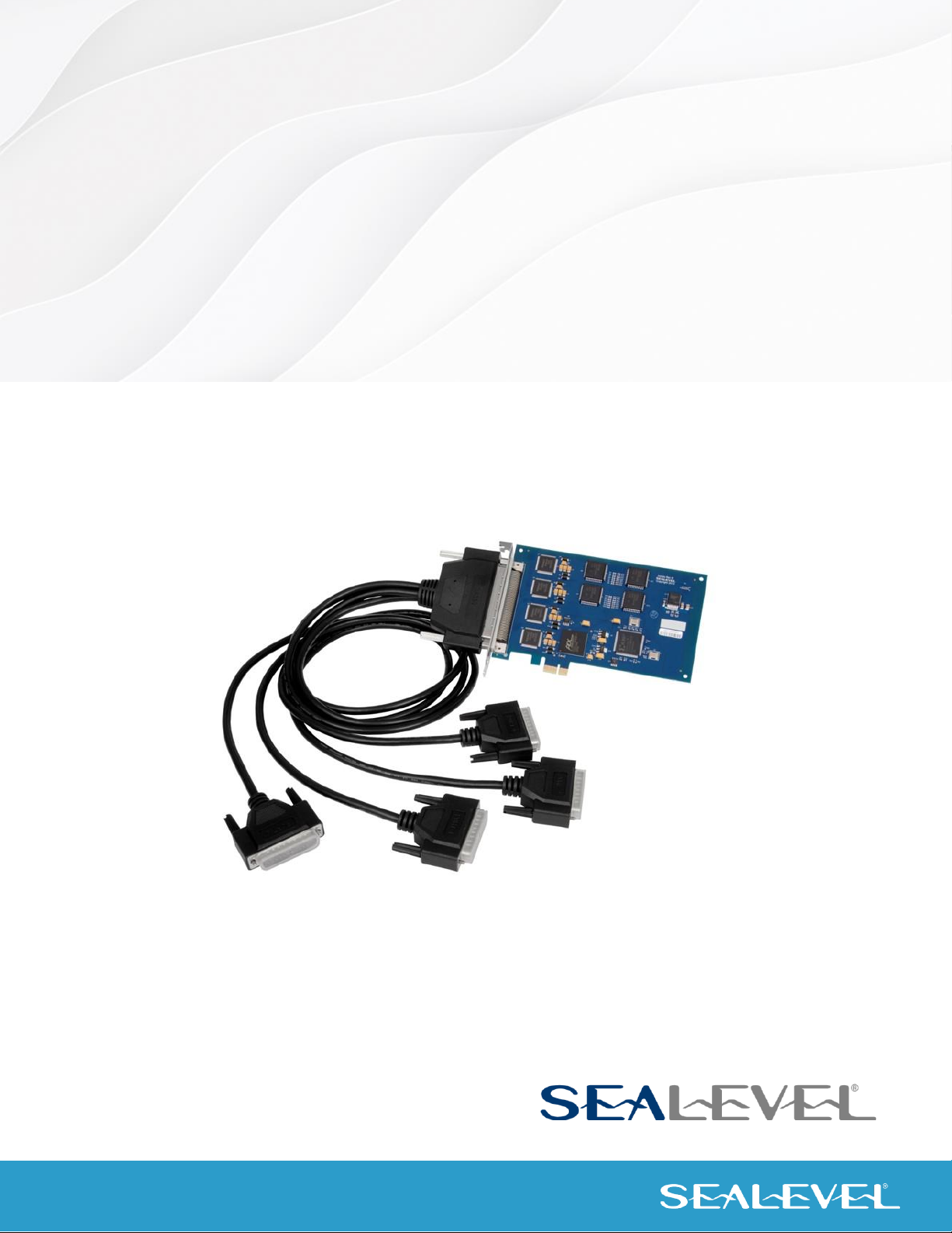
The ACB-MP+4.PCIe (Item# 5402e) is a four-port PCIe bus RS-232, RS-422, RS-485,EIA-530, EIA-530A, V.35
synchronous serial interface. Designed using the popular Zilog Z85230 Enhanced Serial Communication
Controller (ESCC), the board is an ideal solution for military, satellite, radar, banking, and other applications
that require robust synchronous communications.
For maximum flexibility, each of the serial ports can be individually configured for RS-232, RS-422, RS-
485,EIA-530, EIA-530A, V.35 communications. In RS-232 mode, all common modem control signals are
implemented for compatibility with a wide range of peripherals. A digital phase lock loop (DPLL) is included
on each port, and the board supports data rates up to 128K bps in burst mode. For easy implementation, a
fan-out cable is included that terminates the onboard 100-pin connector to four DB-25M connectors.
The ACB-MP+4.PCIe features a PCIe 1.1 interface and will operate on x1, x4, x8 or x16 PCIe Bus slots.
Software support, critical for successful synchronous communication development, is provided through
Sealevel’s SeaMAC driver. HDLC/SDLC protocols are supported as well as certain configurations of
Monosync, Bi-sync, and Raw modes.
The ACB-MP+4.PCIe also utilizes the Exar SP-506 multi-protocol electrical interface chip that allows the
ACB-MP+4.PCIe to be compliant with EIA/TIA-530/530A, EIA/TIA-232E, EIA/TIA 485, and ITU V.35.
Optional cables are available to connect RS-449, RS-530, RS-530A, V.35 and X.21 interfaces.
Features
•Compliant with RoHS and WEEE directives
•Each port individually configurable for RS-232, RS-422, RS-485, RS-530, RS-530A, or V.35
•Z85230 Enhanced Serial Communications Controller (ESCC)
•Data rates to 128K bps (Burst mode)
•Included fan-out cable terminates 100-pin SCSI-style connector on board to four DB-25M
connectors (Item# CA339)

4
© Sealevel Systems, Inc. 5402e Manual | SL9233 8/2021
Before You Get Started
What’s Included
The ACB-MP+4.PCIe is shipped with the following items. If any of these items are missing or damaged,
please contact Sealevel for replacement.
•ACB-232.PCIe Adapter (Item# 5402e)
•100-Pin to (4) DB25M Breakout Cable, 36” in length (Item# CA339)
Advisory Conventions
Warning
The highest level of importance used to stress a condition where damage could result to the
product, or the user could suffer serious injury.
Important
The middle level of importance used to highlight information that might not seem obvious or a
situation that could cause the product to fail.
Note
The lowest level of importance used to provide background information, additional tips, or other
non-critical facts that will not affect the use of the product.

5
© Sealevel Systems, Inc. 5402e Manual | SL9233 8/2021
Optional Items
Depending upon your application, you are likely to find one or more of the following items useful for
interfacing the ACB-MP+4.PCIe to real-world signals. All items can be purchased from our website
(http://www.sealevel.com) or by calling (864) 843-4343.
Cables and Converters
DB25 Female to DB25 Male Extension Cable, 72 inch Length (Item# CA104)
The CA104 is a standard DB25F to DB25M serial extension
cable. Extend a DB25 cable or locate a piece of hardware where
it is needed with this six foot (72 inch) cable. The connectors
are pinned one-to-one, so the cable is compatible with any
device or cable with DB25 connectors. The cable is fully
shielded against interference and the connectors are molded to
provide strain relief. Dual metal thumbscrews secure the cable
connections and prevent accidental disconnection.
Recommended for applications with data rates less than 1M
bps.
DB25 Female (RS-530) to DB37 Male (RS-449 DTE) Cable, 10 inch Length (Item# CA107)
DB25 Female (RS-530) to DB37 Male (RS-449 DTE) Cable, 10
inch Length. RS-530 was designed to replace the bulky DB37
RS-449 connector. The CA107 cable allows any Sealevel RS-530
adapter to be used in an RS-449 application.
DB25 Female (RS-530) to DB15 Male (X.21) Cable, 72 inch Length (Item# CA159)
DB25 Female (RS-530) to DB15 Male (X.21) Cable, 72 inch
Length. Converts the Standard DB25 implementation of RS-530
or RS-422 to the ITU-T X.21 standard pinout.
DB25 Female to DB25 Male (RS-530) Twisted Pair Serial Cable, 72 inch Length (Item#
CA174)
DB25 Female to DB25 Male Twisted Pair Serial Cable, 72 inch
Length. Twisted Pairs provide increased data integrity in high-
speed serial applications. Recommended for RS-530
applications with data rates greater than 1M bps.
DB25 Female (V.35) to ITU-T ISO-2593 Style Connector (V.35) Cable, 72 inch Length
(Item# CA178)
DB25 Female (V.35) to ITU-T ISO-2593 Style Connector (V.35)
Cable, 72 inch Length. The CA178 converts the Sealevel DB25
implementation of V.35 to the ITU-T V.35 mechanical standard.

6
© Sealevel Systems, Inc. 5402e Manual | SL9233 8/2021
Installation & Configuration
Software Installation
Microsoft Windows XP/Vista/Windows 7™ Operating Systems
Do not install the adapter until the software has been successfully installed.
1. Begin by locating, selecting, and installing the correct software from the Sealevel software driver
database.
2. Type in or select the part number (5402e) for the adapter from the listing. Select ‘Download Now’
for the correct version of SeaMAC software compatible with your system.
3. The setup files will automatically detect the operating environment and install the proper
components. Follow the information presented on the screens that follow.
4. A screen may appear with text similar to: “The publisher cannot be determined due to the problems
below: Authenticode signature not found.” Please click the ‘Yes’ button and proceed with the
installation. This declaration simply means that the operating system is not aware of the driver
being loaded. It will not cause any harm to your system.
5. During setup, the user may specify installation directories and other preferred configurations. This
program also adds entries to the system registry that are necessary for specifying the operating
parameters for each driver. An uninstall option is also included to remove all registry/INI file entries
from the system.
6. The software is now installed, and you can proceed with the hardware installation.

7
© Sealevel Systems, Inc. 5402e Manual | SL9233 8/2021
Hardware Installation
The adapter can be installed in any x1, x4, x8 or x16 PCIe expansion slot.
Do not install the adapter until the software has been successfully installed.
1. Turn off power. Disconnect the power cord.
2. Remove the PC case cover.
3. Locate an available PCIe slot and remove the blank metal slot cover.
4. Gently insert the PCIe adapter into the slot. Make sure the adapter is seated properly.
5. Replace the screw (required for FCC Part 15 compliance).
6. Replace the cover.
7. Connect the power cord and power up the machine.
8. The ACB-MP+4.PCIe is to be installed when the system is booted.

8
© Sealevel Systems, Inc. 5402e Manual | SL9233 8/2021
Technical Description
The ACB-MP+4.PCIe utilizes the Zilog Z85230 Enhanced Serial Communications Controller (ESCC) and
includes a dedicated Z85230 per port. This chip features programmable baud rate, data format and
interrupt control. Refer to the ESCC User Manual, available from Zilog, for details on programming the
85230 ESCC chip in the event you are writing your own driver as opposed to using the SeaMAC driver.
Internal Baud Rate Generator
The baud rate of the ESCC is programmed under software control. The standard oscillator supplied with
the board is 7.3728 MHz. However, other oscillator values can be substituted to achieve different baud
rates. It should be noted that the Z85230 chip is manufactured in different speed ranges and installation of
a different oscillator may also require changing the Z85230.
Control and Status Registers Definition
The control and status registers occupy 16 consecutive I/O locations. The following tables provide a
functional description of the bit positions. This table is provided for users that desire to write their own
driver.
X = do not care.
Base
Mode
D7
D6
D5
D4
D3
D2
D1
D0
+4
RD
0
IRQST
0
0
0
0
0
DSRA
+5
RD
485CLK
ECHOA
SYNCA_RTS
SYNCA_CTS
AM3
AM2
AM1
AM0
+5
WR
485CLK
ECHOA
SYNCA_RTS
SYNCA_CTS
AM3
AM2
AM1
AM0
+6
RD
0
0
0
0
RLA
LLA
TSETSL
A
RXCOPTA
+6
WR
X
X
X
X
RLA
LLA
TSETSL
A
RXCOPTA
+7
RD
X
X
X
X
IRQST4
IRQST3
IRQST2
IRQST1
+14
RD
SD7
SD6
SD5
SD4
SD3
SD2
SD1
SD0
+15
RD
SD15
SD14
SD13
SD12
SD11
SD10
SD9
SD8

9
© Sealevel Systems, Inc. 5402e Manual | SL9233 8/2021
Technical Description, Continued
Field
Description
IRQST
SCC interrupt status:
1 = No interrupt pending on ESCC
0 = Interrupt pending on ESCC.
DSRA
DSRA:
1 = DSRA not active
0 = DSRA active
LLA
Local Loopback:
1 = LL set
0 = LL not set
RLA
Remote Loopback:
1 = RL set
0 = RL not set
TSETSLA
TSET clock source:
1= Received TXC as source
0 = TRXCA as source
RXCOPTA
RXCOPTA:
1= Selects SCC PCLK for RTXCA
0 = Selects received RXC for
RTXCA
SYNCA_RTS
SYNCA _RTS:
1 = SYNCA connected to RTS
0 = SYNCA is high
SYNCA_CTS
SYNCA_CTS:
1 = SYNCA connected to CTS
0 = SYNCA is high
485CLK
TSET switches with
TXD:
1 = clk switches
0 = no CLK switching
ECHOA
ECHO enable:
1 = echo disabled
0 = echo enabled
AM0 –AM3
I/O mode select. See table for valid interface options.
0 = High Impedance
SD0 –SD15
Optional security feature. Unique value per customer or
application.
Default value = FFFF
Interface Selection
The ACB-MP+4.PCIe supports a variety of electrical interfaces. Refer to the Control and Status Register
Definitions found in the Technical Description section of this manual for this bit description. There is line
termination on RXD, RXC and TXC in the following modes: RS-530, RS-530A, RS-485T and V.35. This table
is provided for users that desire to write their own driver. By default, at power-up, all signals are high
impedance.
HEX
M3
M2
M1
M0
Interface Mode
0
0
0
0
0
All signals are high impedance
1
0
0
0
1
* not supported *
2
0
0
1
0
RS-232
3
0
0
1
1
* not supported *
4
0
1
0
0
RS-485T with 120termination
5
0
1
0
1
RS-485 without termination
6,7,8,9
0
1
1
0
* not supported *
A
1
0
1
0
single ended loopback
B
1
0
1
1
differential loopback
C
1
1
0
0
* not supported *
D
1
1
0
1
RS-530
E
1
1
1
0
V.35
F
1
1
1
1
RS-530A

10
© Sealevel Systems, Inc. 5402e Manual | SL9233 8/2021
Technical Description, Continued
100-Pin Connector Pin Out
The ACB-MP+4.PCIe has a 100-pin high-density connector and includes a cable (Item# CA339) that breaks
out to four (4) DB25 male connectors. The pin outs for RS-232, RS-485, RS-530, RS-530A and V.35 interfaces
on the DB25 connectors are listed on the following pages. For customers designing their own cable, the
mating 100-pin connector is AMP Part# 5787169-9. The pin out for the 100-pin connector is listed below.
100-Pin Connector
Signal Name
DB25
Port 1
Port 2
Port 3
Port 4
N/C
1
51
26
76
GND
7
2
52
27
77
TXD-
2
3
53
28
78
TXD+
14
4
54
29
79
RTS-
4
5
55
30
80
RTS+
19
6
56
31
81
DTR-
20
7
57
32
82
DTR+
23
8
58
33
83
TSET-
24
9
59
34
84
TSET+
11
10
60
35
85
RXD-
3
11
61
36
86
RXD+
16
12
62
37
87
CTS-
5
13
63
38
88
CTS+
13
14
64
39
89
DSR-
6
15
65
40
90
DSR+
22
16
66
41
91
DCD-
8
17
67
42
92
DCD+
10
18
68
43
93
TXC-
15
19
69
44
94
TXC+
12
20
70
45
95
RXC-
17
21
71
46
96
RXC+
9
22
72
47
97
LL-
18
23
73
48
98
RL-
21
24
74
49
99
NC
25
75
50
100
SHIELD
Shell
Shell
Shell
Shell
Shell

11
© Sealevel Systems, Inc. 5402e Manual | SL9233 8/2021
Technical Description, Continued
DB-25M Connector Pin Outs
RS-232 Signals
Base+5, M3-M0=2, 0010
Pin #
Signal
Name
Mode
2
TD
Transmit Data
Output
3
RD
Receive Data
Input
4
RTS
Request To Send
Output
5
CTS
Clear To Send
Input
6
DSR
Data Set Ready
Input
7
GND
Ground
8
DCD
Data Carrier Detect
Input
15
TXC
Transmit Clock
Input
17
RXC
Receive Clock
Input
18
LL
Local Loopback
Output
20
DTR
Data Terminal Ready
Output
21
RL
Remote Loopback
Output
24
TSET
Transmit Signal Element Timing
Output
RS-485 or RS-485T
Base+5, M3-M0=4, 0100 (With termination)
Base+5, M3-M0=5, 0101 (Without termination)
Pin #
Signal
Name
Mode
2
TDA TX–
Transmit Negative
Output
3
RDA RX–
Receive Negative
Input
7
GND
Ground
9
RXCB RXC+
Receive Clock Positive
Input
11
TSETB TSET+
Transmit Signal Element Timing +
Output
12
TXCB TXC+
Transmit Clock Positive
Input
14
TDB TX+
Transmit Positive
Output
15
TXCA TXC–
Transmit Clock Negative
Input
16
RDB RX+
Receive Positive
Input
17
RXCA RXC–
Receive Clock Negative
Input
24
TSETA TSET–
Transmit Signal Element Timing –
Output

12
© Sealevel Systems, Inc. 5402e Manual | SL9233 8/2021
Technical Description, Continued
DB-25M Connector Pin Outs
RS-530 (RS-422)
Base+5, M3-M0=D, 1101
Pin #
Signal
Name
Mode
2
TDA TX–
Transmit Negative
Output
3
RDA RX–
Receive Negative
Input
4
RTSA RTS–
Request To Send Negative
Output
5
CTSA CTS–
Clear To Send Negative
Input
6
DSRA DSR–
Data Set Ready Negative
Input
7
GND
Ground
8
DCDA DCD–
Data Carrier Detect Negative
Input
9
RXCB RXC+
Receive Clock Positive
Input
10
DCDB DCD+
Data Carrier Detect Positive
Input
11
TSETB TSET+
Transmit Signal Element Timing +
Output
12
TXCB TXC+
Transmit Clock Positive
Input
13
CTSB CTS+
Clear To Send Positive
Input
14
TDB TX+
Transmit Positive
Output
15
TXCA TXC–
Transmit Clock Negative
Input
16
RDB RX+
Receive Positive
Input
17
RXCA RXC–
Receive Clock Negative
Input
18
LL
Local Loopback
Output
19
RTSB RTS+
Request To Send Positive
Output
20
DTRA DTR–
Data Terminal Ready Negative
Output
21
RL
Remote Loopback
Output
22
DSRB DSR+
Data Set Ready Positive
Input
23
DTRB DTR+
Data Terminal Ready Positive
Output
24
TSETA TSET–
Transmit Signal Element Timing –
Output

13
© Sealevel Systems, Inc. 5402e Manual | SL9233 8/2021
Technical Description, Continued
DB-25M Connector Pin Outs
RS-530A
Base+5, M3-M0=F, 1111
Pin #
Signal
Name
Mode
2
TDA TX–
Transmit Negative
Output
3
RDA RX–
Receive Negative
Input
4
RTSA RTS–
Request To Send Negative
Output
5
CTSA CTS–
Clear To Send Negative
Input
6
DSRA DSR–
Data Set Ready Negative
Input
7
GND
Ground
8
DCDA DCD–
Data Carrier Detect Negative
Input
9
RXCB RXC+
Receive Clock Positive
Input
11
TSETB TSET+
Transmit Signal Element Timing +
Output
12
TXCB TXC+
Transmit Clock Positive
Input
13
CTSB CTS+
Clear To Send Positive
Input
14
TDB TX+
Transmit Positive
Output
15
TXCA TXC–
Transmit Clock Negative
Input
16
RDB RX+
Receive Positive
Input
17
RXCA RXC–
Receive Clock Negative
Input
18
LL
Local Loopback
Output
19
RTSB RTS+
Request To Send Positive
Output
20
DTRA DTR–
Data Terminal Ready Negative
Output
21
RL
Remote Loopback
Output
24
TSETA TSET–
Transmit Signal Element Timing –
Output

14
© Sealevel Systems, Inc. 5402e Manual | SL9233 8/2021
Technical Description, Continued
DB-25M Connector Pin Outs
V.35 Signals
Base+5, M3-M0=E, 1110
Pin #
Signal
Name
V.35
Mode
2
TDA TX–
Transmit Negative
P
Output
3
RDA RX–
Receive Negative
R
Input
4
RTS
Request To Send
C
Output *
5
CTS
Clear To Send
D
Input *
6
DSR
Data Set Ready
E
Input *
7
GND
Ground
B
8
DCD
Data Carrier Detect
F
Input *
9
RXCB RXC+
Receive Clock Positive
X
Input
11
TSETB TSET+
Transmit Signal Element Timing +
W
Output
12
TXCB TXC+
Transmit Clock Positive
AA
Input
14
TDB TX+
Transmit Positive
S
Output
15
TXCA TXC–
Transmit Clock Negative
Y
Input
16
RDB RX+
Receive Positive
T
Input
17
RXCA RXC–
Receive Clock Negative
V
Input
18
LL
Local Loopback
Output *
20
DTR
Data Terminal Ready
H
Output *
21
RL
Remote Loopback
Output *
24
TSETA TSET–
Transmit Signal Element Timing –
U
Output
All modem control signals are single ended (un-balanced) with RS-232 signal levels.

15
© Sealevel Systems, Inc. 5402e Manual | SL9233 8/2021
Technical Specifications
Environmental Specifications
Specification
Operating
Storage
Temperature Range
0° to 70°C (32° to 158°F)
-50° to 105°C (-58° to 221°F)
Humidity Range
10 to 90% R.H. Non-Condensing
Power Requirements
Supply line
+3.3 VDC
+12 VDC
Rating
mA
TBD mA
Dimensions
Length
6.53 inches (16.58 cm)
Height
4.20 inches (10.69 cm)
Manufacturing
All Sealevel Systems Printed Circuit boards are built to UL 94V0 rating and are 100% electrically tested.
These printed circuit boards are solder mask over bare copper or solder mask over tin nickel.

16
© Sealevel Systems, Inc. 5402e Manual | SL9233 8/2021
Appendix A –Handling Instructions
ESD Warnings
Electrostatic Discharges (ESD)
A sudden electrostatic discharge can destroy sensitive components. Proper packaging and grounding rules
must therefore be observed. Always take the following precautions.
•Transport boards and cards in electrostatically secure containers or bags.
•Keep electrostatically sensitive components in their containers, until they arrive at an
electrostatically protected workplace.
•Only touch electrostatically sensitive components when you are properly grounded.
•Store electrostatically sensitive components in protective packaging or on anti-static mats.
Grounding Methods
The following measures help to avoid electrostatic damage to the device:
•Cover workstations with approved antistatic material. Always wear a wrist strap connected to
workstation as well as properly grounded tools and equipment.
•Use antistatic mats, heel straps, or air ionizers for more protection.
•Always handle electrostatically sensitive components by their edge or by their casing.
•Avoid contact with pins, leads, or circuitry.
•Keep work area free of non-conductive materials such as ordinary plastic assembly aids and
Styrofoam.
•Use field service tools such as cutters, screwdrivers, and vacuum cleaners, which are conductive.

17
© Sealevel Systems, Inc. 5402e Manual | SL9233 8/2021
Appendix B –Troubleshooting
Following these simple steps can eliminate most common problems.
1. Read this manual thoroughly before attempting to install the adapter in your system.
2. Install software first. This places the required installation files in the correct locations. After
installing the software, proceed to the physical installation section of this manual.
3. Identify all I/O adapters currently installed in your system. This includes your on-board serial ports,
controller cards, sound cards, etc. The I/O addresses used by these adapters, as well as the IRQ (if
any) should be identified.
4. Configure your Sealevel Systems adapter so that there is no conflict with currently installed
adapters. No two adapters can occupy the same I/O address.
5. Make sure the Sealevel Systems adapter is securely installed.
6. For Windows 2000/XP/Vista, and Windows 7, the diagnostic tool ‘WinSSD’ is installed the SeaMAC
folder on the Start Menu during the setup process. First find the ports using the Device Manager,
then use ‘WinSSD’ to verify that the ports are functional. The Loopback tab is primarily designed
for asynchronous cards and should not be used in synchronous modes –use the BERT tab instead.
7. Always use Sealevel Systems diagnostic software when troubleshooting a problem. This will
eliminate any software issues from the equation.
If these steps do not solve your problem, please call Sealevel Technical Support at +1864-843-4343. Our
technical support is free and available Monday through Friday from 8:00 am –5:00 pm EST. For email
support, contact support@sealevel.com.

18
© Sealevel Systems, Inc. 5402e Manual | SL9233 8/2021
Appendix C –Electrical Interface
RS-232
Quite possibly the most widely used communication standard is RS 232. This implementation has been
defined and revised several times and is often referred to as RS 232 or EIA/TIA 232. It is defined by the EIA
as the Interface between Data Terminal Equipment and Data Circuit- Terminating Equipment Employing
Serial Binary Data Interchange. The mechanical implementation of RS 232 is on a 25 pin D sub connector.
RS 232 is capable of operating at data rates up to 20 Kbps at distances less than 50 ft. The absolute
maximum data rate may vary due to line conditions and cable lengths. RS 232 often operates at 38.4 Kbps
over very short distances. The voltage levels defined by RS 232 range from -12 to +12 volts. RS 232 is a
single ended or unbalanced interface, meaning that a single electrical signal is compared to a common
signal (ground) to determine binary logic states. A voltage of +12 volts (usually +3 to +10 volts) represents
a binary 0 (space) and -12 volts ( -3 to -10 volts) denotes a binary 1 (mark). The RS-232 and the EIA/TIA-
574 specification defines two type of interface circuits, Data Terminal Equipment (DTE) and Data Circuit-
Terminating Equipment (DCE). The Sealevel Systems adapter is a DTE interface.
RS-422
The RS 422 specification defines the electrical characteristics of balanced voltage digital interface circuits.
RS 422 is a differential interface that defines voltage levels and driver/receiver electrical specifications. On
a differential interface, logic levels are defined by the difference in voltage between a pair of outputs or
inputs. In contrast, a single ended interface, for example RS 232, defines the logic levels as the difference
in voltage between a single signal and a common ground connection. Differential interfaces are typically
more immune to noise or voltage spikes that may occur on the communication lines. Differential interfaces
also have greater drive capabilities that allow for longer cable lengths. RS 422 is rated up to 10 Megabits
per second and can have cabling 4000 feet long. RS 422 also defines driver and receiver electrical
characteristics that will allow 1 driver and up to 32 receivers on the line at once. RS 422 signal levels range
from 0 to +5 volts. RS 422 does not define a physical connector.
RS-485
RS 485 is backwardly compatible with RS 422; however, it is optimized for party-line or multi drop
applications. The output of the RS 422/485 driver is capable of being Active (enabled) or Tri State (disabled).
This capability allows multiple ports to be connected in a multi drop bus and selectively polled. RS 485
allows cable lengths up to 4000 feet and data rates up to 10 Megabits per second. The signal levels for RS
485 are the same as those defined by RS 422. RS 485 has electrical characteristics that allow for 32 drivers
and 32 receivers to be connected to one line. This interface is ideal for multi drop or network environments.
RS 485 tri state driver (not dual state) will allow the electrical presence of the driver to be removed from
the line. Only one driver may be active at a time and the other driver(s) must be tri stated. RS 485 can be
cabled in two ways, two wire and four wire mode. Two wire mode does not allow for full duplex
communication and requires that data be transferred in only one direction at a time. For half duplex
operation, the two transmit pins should be connected to the two receive pins (Tx+ to Rx+ and Tx- to Rx- ).
Four wire mode allows full duplex data transfers. RS 485 does not define a connector pin out or a set of
modem control signals. RS 485 does not define a physical connector.

19
© Sealevel Systems, Inc. 5402e Manual | SL9233 8/2021
Appendix C –Electrical Interface, Continued
RS-530/530A
RS 530 (a.k.a. EIA 530) compatibility means that RS 422 signal levels are met, and the pin out for the DB 25
connector is specified. The EIA (Electronic Industry Association) created the RS 530 specification to detail
the pin out and define a full set of modem control signals that can be used for regulating flow control and
line status. The major difference between RS-530 and RS-530A lies in some of the modem control interface
signals. In RS-530 the signals all of the modem control signals are differential, in RS-530A some of these
signals are single ended. The RS 530 specification defines two types of interface circuits, Data Terminal
Equipment (DTE) and Data Circuit-Terminating Equipment (DCE). The Sealevel Systems adapter is a DTE
interface.
V.35
V.35 is a standard defined by ITU (formerly CCITT) that specifies an electrical, mechanical, and physical
interface that is used extensively by high-speed digital carriers such as AT&T Dataphone Digital Service
(DDS). ITU V.35 is an international standard that is often referred to as Data Transmission at 48 Kbps using
60 - 108 KHz Group-Band Circuits. ITU V.35 electrical characteristics are a combination of unbalanced
voltage and balanced current mode signals. Data and clock signals are balanced current mode circuits.
These circuits typically have voltage levels from 0.5 Volts to -0.5 Volts (1 Volt differential). The modem
control signals are unbalanced signals and are compatible with RS-232. The physical connector is a 34 pin
connector that supports 24 data, clock, and control signals. The physical connector is defined in the ISO-
2593 standard. ITU V.35 specification defines two types of interface circuits, Data Terminal Equipment
(DTE) and Data Circuit-Terminating Equipment (DCE). The Sealevel Systems adapter is a DTE interface.

20
© Sealevel Systems, Inc. 5402e Manual | SL9233 8/2021
Appendix D –Mechanical Drawing
Table of contents
Other SeaLevel Recording Equipment manuals

SeaLevel
SeaLevel COMM+8.LPCI User manual

SeaLevel
SeaLevel SeaLINK+4.VC User manual

SeaLevel
SeaLevel PLC-16.PCI User manual

SeaLevel
SeaLevel PC-SIO-850 User manual

SeaLevel
SeaLevel ULTRA 485 User manual

SeaLevel
SeaLevel COMM+8.LPCI User manual

SeaLevel
SeaLevel PC-COMM+232 User manual

SeaLevel
SeaLevel ACB-188 User manual

SeaLevel
SeaLevel DIO-104.OPTO User manual

SeaLevel
SeaLevel SeaLINK PIO-96 User manual