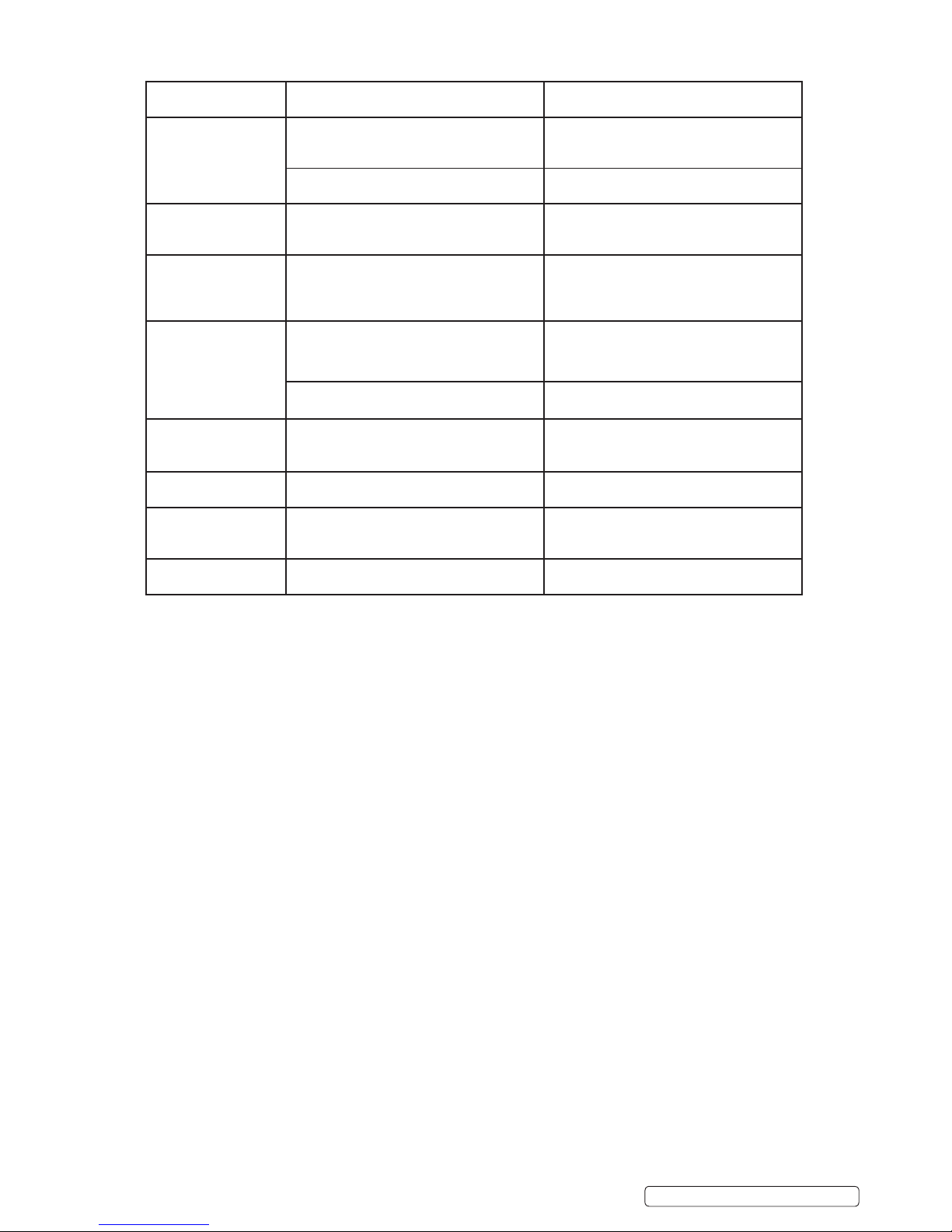
Sealey BSCU100 User manual

INSTRUCTIONS FOR
COMBINED BATTERY SUPPORT UNIT AND CHARGER 100A
MODEL NO: BSCU100
Thank you for purchasing a Sealey product. Manufactured to a high standard, this product will, if used according to these instructions,
and properly maintained, give you years of trouble free performance.
IMPORTANT: PLEASE READ THESE INSTRUCTIONS CAREFULLY. NOTE THE SAFE OPERATIONAL REQUIREMENTS, WARNINGS & CAUTIONS. USE
THE PRODUCT CORRECTLY AND WITH CARE FOR THE PURPOSE FOR WHICH IT IS INTENDED. FAILURE TO DO SO MAY CAUSE DAMAGE AND/OR
PERSONAL INJURY AND WILL INVALIDATE THE WARRANTY. KEEP THESE INSTRUCTIONS SAFE FOR FUTURE USE.
1. SAFETY
1.1. ELECTRICAL SAFETY
WARNING! It is the user’s responsibility to check the following:
Check all electrical equipment and appliances to ensure that they are safe before using. Inspect power supply leads, plugs and all
electrical connections for wear and damage. Sealey recommend that an RCD (Residual Current Device) is used with all electrical
products. You may obtain an RCD by contacting your local Sealey dealer.
if the product is used in the course of business duties, it must be maintained in a safe condition and routinely PAT (Portable Appliance
Test) tested.
Electrical safety information, it is important that the following information is read and understood.
1.1.1. Ensure that the insulation on all cables and on the appliance is safe before connecting it to the power supply.
1.1.2. Regularly inspect power supply cables and plugs for wear or damage and check all connections to ensure that they are secure.
1.1.3. Important: Ensure that the voltage rating on the appliance suits the power supply to be used and that the plug is tted with the correct
fuse - see fuse rating in these instructions.
8DO NOT pull or carry the appliance by the power cable.
8DO NOT pull the plug from the socket by the cable.
8DO NOT use worn or damaged cables, plugs or connectors. Ensure that any faulty item is repaired or
replaced immediately by a qualied electrician.
1.1.4. This product is tted with a BS1363/A 13 Amp 3 pin plug.
If the cable or plug is damaged during use, switch the electricity supply and remove from use.
Ensure that repairs are carried out by a qualied electrician.
Replace a damaged plug with a BS1363/A 13 Amp 3 pin plug. If in doubt contact a qualied electrician.
A) Connect the GREEN/YELLOW earth wire to the earth terminal ‘E’.
b) Connect the BROWN live wire to the live terminal ‘L’.
c) Connect the BLUE neutral wire to the neutral terminal ‘N’.
Ensure that the cable outer sheath extends inside the cable restraint and that the restraint is tight.
Sealey recommend that repairs are carried out by a qualied electrician.
1.2. PERSONAL PRECAUTIONS
9Ensure there is another person within hearing range of your voice and close enough to come to your aid, should a problem arise when
working near a lead-acid battery.
9 Wear safety eye protection and protective clothing. Avoid touching eyes while working near battery.
9Have fresh water and soap nearby in case battery acid contacts skin, clothing or eyes.
9 Wash immediately with soap and water if battery acid contacts skin or clothing. If acid enters eye, flush eye immediately with cool, clean
running water for at least 15 minutes and seek immediate medical attention.
9Remove personal metallic items such as rings, bracelets, necklaces and watches. A lead-acid battery can produce a short-circuit current
which is high enough to weld a ring or the like to metal, which would cause severe burns.
9Ensure hands, clothing (especially belts) are clear of fan blades and other moving or hot parts of engine, remove ties and contain long hair.
8DO NOT smoke or allow a spark or flame in the vicinity of battery or engine.
1.3. GENERAL SAFETY INSTRUCTIONS
9Familiarise yourself with the application and limitations of the UNIT as well as the potential hazards. Also refer to the vehicle
manufacturer’s hand book. IF IN ANY DOUBT CONSULT A QUALIFIED ELECTRICIAN.
9Ensure the unit is in good order and condition before use. If in any doubt do not use the unit, contact your Sealey Dealer.
9Use the unit in the upright position only and ensure it is placed on a stable surface which will adequately support its weight.
9 Ensure the unit is disconnected from the mains supply before attaching/detaching the power clamps to/from the battery.
9Keep tools and other items away from the engine and ensure you can see the battery and working parts of engine clearly.
9Ensure that during charging, the unit is placed in a location where there is sufficient ventilation to prevent the build up of explosive
Refer to
Instruction
Manual
Indoor use
Only
Warning:
Corrosive
Sustance
Wear eye
protection
Warning:
Explosive
Material
Battery
Charging:
Ventilate area
Recommended fuse rating
13 Amp
DANGER! BE AWARE, LEAD-ACID BATTERIES GENERATE EXPLOSIVE GASES DURING NORMAL BATTERY OPERATION. FOR THIS
REASON, IT IS VERY IMPORTANT TO READ AND FOLLOW THESE INSTRUCTIONS CAREFULLY, EACH TIME YOU USE THE CHARGING
EQUIPMENT.
Follow these instructions and those published by the battery and vehicle manufacturers, and the maker of any equipment you
intend to use in the vicinity of the battery. Remember to review warning marks on all products and on engines.
BSCU100 | Issue:1 09/11/15
Original Language Version
© Jack Sealey Limited

gases from a lead acid battery, and DO NOT cover or obstruct the unit’s ventilation louvres.
9If battery has caps to access the battery fluid, remove the caps and check the fluid level before connecting the power clamps. If
necessary top-up the battery with distilled water by referring to the battery manufacturer’s instructions (Apply the personal
safety precautions described in part 1.2).
9If the unit receives a sharp knock or blow the unit must be checked by a qualified service agent before using.
If the battery terminals are corroded or dirty clean them before attaching the power clamps.
9Keep children and unauthorised persons away from the working area.
8888 DO NOT disassemble the unit for any reason. The unit must only be checked by qualified service personnel.
8888 DO NOT try to charge a non-rechargeable battery.
8888 DO NOT try to start engine when charger is connected to battery.
8888 DO NOT try to charge battery if battery fluid is frozen.
WARNING! To prevent the risk of sparking, short circuit and possible explosion DO NOT drop metal tools in the battery area, or allow
them to touch the battery terminals.
8888 DO NOT allow power clamps to touch each other or to make contact with any metallic part of the vehicle.
8DO NOT cross connect power leads from charger to battery. Ensure positive (+/RED) is to positive and negative (-/BLACK) is to negative.
8DO NOT pull the cables or clamps from the battery terminals.
8DO NOT use the unit outdoors, or in damp, or wet locations and DO NOT operate within the vicinity of flammable liquids or gases.
8888 DO NOT use unit inside vehicle or inside engine compartment.
8988 Ensure there is effective ventilation to prevent a build-up of explosive gases, and do not cover or obstruct charger ventilation louvres.
8DO NOT use the unit for a task for which it is not designed.
WARNING! DO NOT simultaneously charge batteries of different capacities or discharge levels.
WARNING! If a fuse blows, ensure it is replaced with an identical fuse type and rating. Use only Sealey genuine parts.
8988 When not in use, store the unit carefully in a safe, dry, childproof location.
NOTE: This appliance can be used by children aged from 8 years and above and persons with reduced physical, sensory
or mental capabilities or lack of experience and knowledge if they have been given supervision or instruction
concerning use of the appliance in a safe way and understand the hazards involved. Children shall not play with the
appliance. Cleaning and user maintenance shall not be made by children without supervision.
2. i INTRODUCTION
High frequency power supply utilises a microprocessing CPU controller when charging a battery and providing support during prolonged
electronic diagnostic checks. Designed for use with lead-acid batteries including WET, GEL and AGM types on 12V systems. Includes a function
to recharge a deeply discharged battery. Safety circuitry which includes reverse polarity protection, short circuit protection, overload protection
and the detection of voltage errors. Once fully charged, the battery may be left connected to be automatically conditioned and maintained.
3. SPECIFICATION
Model no: .............................................................. BSCU100
Type: ............................................. Microprocessor controlled
Supply:...........................................................................230V
Output: .............................................................................12V
Output charge: ............................................................1-100A
Battery range: .........................................................5-1000Ah
BSU supply: ..................................100A - 13.8V/14.5V/14.8V
4. ASSEMBLY
4.1. Fit cable holders Refer to g.1
4.1.1. Screw cable holders to each side as shown in g.1.
4.2. Fit cable clamps Refer to g.2
4.2.1. Push cable through insulating handles.
4.2.2. Locate cable using cable screw washer and nut, note which way up
cable needs to be. Screw on cable clamp tightly.
4.2.3. Screw up cable screw tightly.
4.2.4. Push outer protection pieces onto the ends of the clamp.
4.2.5. Slide insulating handles up to meet the outer protection pieces.
4.2.6. Repeat for other clamp.
Fig.1
Fig.2
BSCU100 | Issue:1 09/11/15
Original Language Version
© Jack Sealey Limited

5. CONTROL PANEL
5.1. Signalling LEDs
5.1.1. There are 15 LEDs on the control panel which have the following functions:
5.1.1.1. 4 Battery status LEDs indicating:
Full: battery is charged and is in charge maintenance status
Charging: battery charging
Fault: battery is damaged
Reverse: polarity reversal
5.1.1.2. 1 Battery charger status LED, “ON LED” battery charger is on (colour BLUE).
5.1.1.3. 1 operating status LED (indicates whether output is in accordance with the selected mode).
5.1.1.4. Connected with the Start/Stop button (colour YELLOW).
5.1.1.5. 2 operating mode LEDs “Function” FLASH or CHARGE (colour YELLOW).
5.1.1.6. 4 supplied current LEDs, “Amperage”, described in next chapter (colour YELLOW).
5.1.1.7. 3 supply voltage and battery type LEDs, “Volt/Batt” described in next chapter (colour YELLOW).
5.2. Operating Mode selection buttons
5.2.1. There are 5 buttons:
Start / Stop: starts or stops supply in the selected mode
Function: selects operating mode
Volt / Batt: selects supply voltage or the type of battery to charge
Amperage: selects supplied current
A/V (display): selects the information to be displayed
5.3. Digital Display
5.3.1. The A/V selector button selects voltage or current display.
6. OPERATION
6.1. A) Function - Charge
6.1.1. Battery charging mode. There are 7 charging steps, as described below:
STEP 1: Analysis 1. If the battery output is more than 6.5V, the unit proceeds with the next step. Outputs below 6.5V will
cause the device to revert to stand-by.
STEP 2: Pre-charge. The charge starts at a constant current, until the battery voltage reaches 13V.
STEP 3: Analysis 2. Checks whether the battery has short-circuited elements. The battery charger stops supplying
current for 5 minutes. If during this time the battery voltage falls below 11.7V, the device will revert to stand-by.
If the voltage remains above 11.7V, the battery charger will move on to STEP 4. If any element short-circuits or the
battery becomes sulphated (as conrmed by message ERR02 on the display during STEP 3), the battery should
be charged in the RECOVERY mode.
STEP 4: Deep cycle charging. The battery charges until the set limit value is reached.
STEP 5: Constant voltage. Keeps the battery at the charging end voltage.
STEP 6: Buffer. The voltage falls to the maintenance level and the charging cycle is completed. The green FULL LED will
turn on.
STEP 7: Pulsed current cycle. Pulsed battery maintenance cycle (over long periods).
6.2. Function - Flash
6.2.1. Power Supplier mode assisting in vehicle programming. No charge phase occurs in it. It is just a power supplier stabilized at the
nominal battery voltage. It is designed to deliver current supporting the battery, to prevent it from going at during operations
which require power for short or long periods of time.
6.3. Function - Recovery
6.3.1. Recovery mode for sulphated batteries accessible by a prolonged press of the “Function” key. The screen displays the message
“rEC” and shows the instantaneous voltage or current reading; during this step, the “Charge” LED ashes.
6.3.2. The battery charger performs a special charging cycle, in which higher than average voltages are forced, to attempt recovery of
the battery. In this mode, no error messages are generated during the charging cycle; when the cycle is completed, a message
BSCU100 | Issue:1 09/11/15
Original Language Version
© Jack Sealey Limited

is displayed to indicate whether or not the battery has been recovered on the basis of voltage or current absorption. This mode
has 6 charging steps, as described below:
STEP 1: Analysis 1. If the battery output is more than 3V, the unit proceeds with the next step. Outputs below 3V will
cause the device to revert to stand-by.
STEP 2: Pre-charge. The charge starts at a constant current, until the battery voltage reaches 13V.
STEP 3: Deep cycle charging. The battery charges until the set limit value is reached.
STEP 4: Constant voltage. Keeps the battery at the charging end voltage.
STEP 5: Buffer. The voltage falls to the maintenance level and the charging cycle is completed. The green FULL LED will
turn on.
STEP 6: Pulsed current cycle. Pulsed battery maintenance cycle (over long periods).
ATTENTION: Because of the high voltage reached during this charging cycle, the battery recovery process must be
performed with the battery disconnected from the vehicle. Recovery with the battery connected to the vehicle may result in
damage to the vehicle’s electronics.
6.4. B) Flash - supply and charging mode: “Amperage”
6.4.1. Preset supply current bands:
Flash 10A: supply current set to 10A
Flash 30A: supply current set to 30A
Flash 60A: supply current set to 60A
Flash 100A: supply current set to 100A
6.4.2. Preset charging bands to select the connected battery (output current adjusted automatically).
Charge 5 Ah - 100 Ah: Supports batteries from 5Ah to 100Ah.
Charge 100 Ah - 300 Ah: Supports batteries from 100Ah to 300Ah.
Charge 300Ah - 600 Ah: Supports batteries from 300Ah to 600Ah.
Charge 600Ah – 1000Ah: Supports all batteries from a minimum of 600Ah to a maximum of 1000Ah.
6.5. C) “Flash” supply voltage and supported batteries: “Volt / Batt.”
6.5.1. Preset supply bands:
13.8V: Supply voltage set to 13.8V
14.4V: Supply voltage set to 14.4V
14.8V: Supply voltage set to 14.8V
6.5.2. Preset battery types:
Wet: Acid electrolyte batteries. Charge end at 14.4V
Agm: Agm batteries with at plate or Optima type spiral cell. Charge end at 14.7V
Gel: Batteries with gelatinous electrolyte. Charge end at 14.2V
6.5.3. Saving Settings
The battery charger saves the settings made on the front control panel. In the event of an accidental power loss or voluntary power off,
when the charger is restarted, it will restart with the latest saved settings. With the battery charger set to the FLASH mode, the work
cycle will resume automatically when the power supply is restored. Whereas in the CHARGE mode, the screen will display
the message ER01, and the START/STOP key will have to be pressed, to resume the normal charge cycle.
6.5.4. Battery Analysis
The analysis stages within the operating modes may terminate with the signalling of some errors.
Damaged Battery: the ‘’Fault’’ LED switches on and the ‘’Start / Stop’’ LED switches off, and the charger enters Standy-by
mode. The display shows the message ‘’Errx’’ where ‘x’ is the number corresponding to the cause of the error (see Table 1).
Single two second audible warning.
Polarity reversal: the ‘’Reverse’’ LED switches on, and the display shows the message ‘’Err7’’ with a two second audible
warning.
BSCU100 | Issue:1 09/11/15
Original Language Version
© Jack Sealey Limited

6.5.5.Error codes
The errors that may be reported are described in Table 1
6.6. Battery charging
6.6.1. Charging batteries connected to the vehicle
6.6.1.1. Before starting to charge the battery, make sure the power supply lead is not plugged into the mains supply.
6.6.1.2. Locate the vehicle’s earthing point, which is normally connected to the negative battery terminal.
6.6.1.3. Charging a battery with negative earth, grounded to the vehicle’s chassis.
• Connect the output lead with the red clamp to the positive terminal (+) of the battery.
• Connect the output lead with the black clamp to the vehicle’s earthing point, keeping it away from the battery and from the
fuel pipe.
6.6.1.4. Charging a battery with positive earth, grounded to the vehicle’s chassis.
• Connect the output lead with the black clamp to the negative terminal (-) of the battery.
• Connect the output lead with the red clamp to the vehicle’s earthing point, keeping it away from the battery and from the
fuel pipe.
6.6.2. Connecting batteries that are not connected to a vehicle
6.6.2.1. Before starting to charge the battery, make sure the power supply lead is not plugged into the mains supply.
6.6.2.2. Connect the output lead with the red clamp to the positive terminal (+) of the battery.
6.6.2.3. Connect the output lead with the black clamp to the negative terminal (-) of the battery.
ATTENTION: Make sure both clamps of the output leads generate a suitable contact with their corresponding terminals.
6.6.3. Operating the charger
6.6.3.1. Once the output leads have been connected to the battery, plug the power supply lead of the battery charger into the mains,
making sure the voltage matches the nominal voltage of the battery charger (230V-50Hz); having done this, the charger will emit an
acoustic signal for 0.5 seconds, and all the LED indicators on the control panel will switch on for 2 seconds; at this stage, the
display shows “- - - -”.
6.6.3.2. The battery charger is congured in “stand-by” mode; for example: ON LED lit, WET LED lit, CHARGE LED 5-50Ah lit. The LEDs light
up differently based on the last programme saved (see section “Saving Charging Cycles”).
6.6.3.3. At this stage, with the battery charger in “stand-by” mode, set the charging parameters suitable for the type of battery to be charged,
using the buttons on the control panel. The charging parameters selected are displayed by the corresponding LED, which switches on.
6.6.4. Selectable charging parameters:
• Function key: (see section A – Operating Modes: “Function”) depending on the work cycle, select:
- Flash, Charge or Recovery.
• Amperage key: (see section B – Supply and charging mode: “Amperage”)
6.6.4.1. Based on the supply current required to support the battery voltage during reprogramming operations, you can select four different
supply currents:
DISPLAY INDICATION
CAUSE SOLUTION
E01 Leads disconnected, leads short-circuited. Position the clamps correctly and start
charging the battery again (see section
“Operating the Charger”).
Battery completely short-circuited. The battery could be defective. Contact your
nearest battery service centre.
E02 Battery faulty or unrecoverable.
No current accepted after 20 hours of
recovery.
The battery could be defective. Contact your
nearest battery service centre.
E03 Internal overheating of battery charger.
Battery charger overload.
Remove any objects that could be covering
the ventilation area of the battery charger or
move it to a cooler area. Wait for the battery
charger to start again automatically.
E04 Voltage error. Set the voltage corresponding to that of the
battery again. Start charging the battery again
(see section, “ Operating the charger”).
One or more elements of the battery has/have
short-circuited.
The battery could be defective. Contact your
nearest battery service centre.
E05 Battery voltage too high compared to that set
(you are attempting to charge a 24V battery.
Only use the battery charger with batteries
supported at 12V. Start charging the battery
again (see section “Operating the charger”).
E06 Battery capacity excessive.
Unable to reach end condition.
Use a battery charger with greater capacity.
E07 and LED
REVERSE
The clamps of the output leads are not
connected correctly to the battery.
Position the clamps correctly and start
charging the battery again, (see section
“Operating the charger”).
E08 Excessively high output current. Current
exceeds maximum limit.
Reduce battery absorption.
BSCU100 | Issue:1 09/11/15
Original Language Version
© Jack Sealey Limited

Sole UK Distributor, Sealey Group.
Kempson Way, Suffolk Business Park,
Bury St. Edmunds, Suffolk.
IP32 7AR
www.sealey.co.uk
sales@sealey.co.uk
01284 757500
01284 703534
Web
Environmental Protection
Recycle unwanted materials instead of disposing of them as waste. All tools, accessories and packaging should be sorted,
taken to a recycling centre and disposed of in a manner which is compatible with the environment.
WEEE Regulations
Dispose of this product at the end of its working life in compliance with the EU Directive on Waste Electrical and Electronic
Equipment (WEEE). When the product is no longer required, it must be disposed of in an environmentally protective way.
Contact your local solid waste authority for recycling information.
BSCU100 | Issue:1 09/11/15
Original Language Version
© Jack Sealey Limited
If you select the FLASH function, you can choose among the following options:
Flash 10A: the battery charger delivers a constant current of 10A
Flash 30A: the battery charger delivers a constant current of 30A
Flash 60A: the battery charger delivers a constant current of 60A
Flash 100A: the battery charger delivers a constant current of 100A
If you select the CHARGE function: Based on the capacity of the battery, select:
Charge 5 Ah - 100 Ah: Supports batteries from 5Ah to 100Ah
Charge 100 Ah - 300 Ah: Supports batteries from 100Ah to 300Ah
Charge 300 Ah - 600 Ah: Supports batteries from 300Ah to 600Ah
Charge 600 Ah - 1000 Ah: Supports all batteries from a minimum of 600Ah to a maximum of 1000Ah
• Volt / Batt key (see section C - “Flash” supply voltages and supported batteries: “Volt / Batt.”)
6.6.4.2. Depending on the supply voltage required to support the battery voltage during reprogramming operations (ONLY FLASH MODE), you
can select three different supply voltages:
13.8V: Supply voltage set to 13.8V
14.4V: Supply voltage set to 14.4V
14.8V: Supply voltage set to 14.8V
6.6.4.3. Depending on the construction/type of the battery (ONLY CHARGE MODE), select: Wet, Gel or Agm.
6.6.5. Once the charging parameters have been set, press the START/STOP key to start charging the battery. When the START/STOP and
CHARGING LEDs light up, the battery is being charged; the display will show the charging current and the voltage of the battery.
6.6.6. The CHARGING LED remains lit in phases “I” and “U0” whilst the battery is charging.
6.6.7. When the FULL LED switches on, it means that the battery is fully charged (100%), and the charger will switch to the maintenance
phase, keeping the state of efciency of the battery constantly monitored, so that it is always at an optimal level of charge. In this
charging phase, the appliance can be left connected to the battery for several months.
6.6.8. If you wish to end or interrupt the charging cycle, follow the charge end/interruption instructions.
6.6.9. Intentional interruption of the charging cycle
6.6.9.1. If you want to interrupt the battery charging cycle, simply press the START/STOP key; the corresponding LED will switch off to
show that the work cycle has ended. At this stage, it is recommended to disconnect the output leads from the battery terminals.
6.6.10. Interruption of the charging cycle due to power cut
6.6.10.1. In the case of a 230V mains power supply cut, the charger saves the work cycle that it was performing in order to restore it
automatically (only in the FLASH mode) as soon as the 230V power supply is restored. This function is fundamental if the battery
charger is used to charge batteries without the operator supervising the cycle; for example, during very long reprogramming cycles.
6.6.10.2. Whereas, in the CHARGE mode, the START/STOP button must be pressed to resume the work cycle.
6.6.11. End of charging
6.6.11.1. Once the battery is charged, press the START/STOP key of the battery charger. The LED will turn off to show that the battery charger
has completed the work cycle.
6.6.11.2. Disconnect the power supply cable from the mains.
6.6.11.3. Disconnect the output lead with the black clamp from the vehicle’s earthing point or from the negative terminal (-) of the battery.
6.6.11.4. Disconnect the output lead with the red clamp from the positive terminal (+) of the battery.
7. MAINTENANCE
7.1. When the battery charger is not being used, it must be stored in a dry place to protect it against humidity. Disconnect the battery
charger and use a soft cloth to clean its outer casing.
NOTE: It is our policy to continually improve products and as such we reserve the right to alter data, specifications and component parts without prior notice.
IMPORTANT: No liability is accepted for incorrect use of this product.
WARRANTY: Guarantee is 12 months from purchase date, proof of which will be required for any claim.
Table of contents
Other Sealey Batteries Charger manuals

Sealey
Sealey ECS650 User manual

Sealey
Sealey DSBC8 User manual

Sealey
Sealey Autocharge10s User manual

Sealey
Sealey AUTOCHARGE 6.V2 User manual

Sealey
Sealey Autocharge15s User manual

Sealey
Sealey SPI2S User manual

Sealey
Sealey SCI6S User manual

Sealey
Sealey CP108VMC User manual

Sealey
Sealey WCB3 User manual

Sealey
Sealey SPI3S.V2 User manual

Sealey
Sealey SMC01.V3 User manual

Sealey
Sealey SCI12S User manual

Sealey
Sealey SMC03 User manual

Sealey
Sealey SMC02.V3 User manual

Sealey
Sealey SUPERSTART550 User manual

Sealey
Sealey CP108VMCEU User manual

Sealey
Sealey CHARGE106 User manual

Sealey
Sealey POWER PRODUCTS SUPERCHARGE Series User manual

Sealey
Sealey SPBC30 User manual

Sealey
Sealey BOOST120 User manual