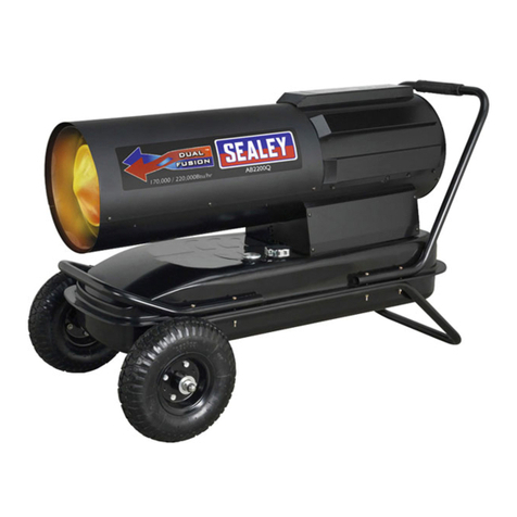
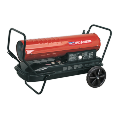
Sealey AB125HE User manual

INSTRUCTIONS FOR:
PARAFFIN SPACE HEATERS (C/W CHIMNEY)
MODELS: AB125HE & AB180HE
Thank you for purchasing a Sealey product. Manufactured to a high standard this product will, if used according to these instructions
and properly maintained, give you years of trouble free performance.
IMPORTANT: PLEASE READ THESE INSTRUCTIONS CAREFULLY. NOTE THE SAFE OPERATIONAL REQUIREMENTS, WARNINGS AND CAUTIONS.
USE THE PRODUCT CORRECTLY AND WITH CARE FOR THE PURPOSE FOR WHICH IT IS INTENDED. FAILURE TO DO SO MAY CAUSE DAMAGE
AND/OR PERSONAL INJURY AND WILL INVALIDATE THE WARRANTY. PLEASE KEEP INSTRUCTIONS SAFE FOR FUTURE USE.
1. SAFETY INSTRUCTIONS
1.1. ELECTRICAL SAFETY
p WARNING! It is the responsibility of the owner and the operator to read, understand and comply with the following:
You must check all electrical products, before use, to ensure that they are safe. You must inspect power cables, plugs, sockets and any other
connectors for wear or damage. You must ensure that the risk of electric shock is minimised by the installation of appropriate safety devices. A
Residual Current Circuit Breaker (RCCB) should be incorporated in the main distribution board. We also recommend that a Residual Current
Device (RCD) is used. It is particularly important to use an RCD with portable products that are plugged into a supply which is not protected by
an RCCB. If in any doubt consult a qualified electrician. You may obtain a Residual Current Device by contacting your Sealey dealer.
You must also read and understand the following instructions concerning electrical safety.
1.1.1. The Electricity at Work Act 1989 requires all portable electrical appliances, if used on business premises, to be tested by a qualified
electrician, using a Portable Appliance Tester (PAT), at least once a year.
1.1.2. The Health & Safety at Work Act 1974 makes owners of electrical appliances responsible for the safe condition of those appliances
and the safety of the appliance operators. If in any doubt about electrical safety, contact a qualified electrician.
1.1.3. Ensure that the insulation on all cables and on the appliance is safe before connecting it to the power supply. See 1.1.1. and 1.1.2.
and use a Portable Appliance Tester.
1.1.4. Ensure that cables are always protected against short circuit and overload.
1.1.5. Regularly inspect power supply cables and plugs for wear or damage and check all
connections to ensure that none is loose.
1.1.6. Important: Ensure that the voltage marked on the appliance matches the power supply
to be used and that the plug is fitted with the correct fuse - see fuse rating at right.
1.1.7. DO NOT pull or carry the appliance by the power cable.
1.1.8. DO NOT pull the plug from the socket by the cable.
1.1.9. DO NOT use worn or damaged cables, plugs or connectors. Immediately have any faulty
item repaired or replaced by a qualified electrician. When an ASTA/BS approved UK
3 pin plug is damaged, cut the cable just above the plug and dispose of the plug safely.
Fit a new plug according to the following instructions (UK only).
a) Connect the GREEN/YELLOW earth wire to the earth terminal E.
b) Connect the BROWN live wire to the live terminal L.
c) Connect the BLUE neutral wire to the neutral terminal N.
d) After wiring, check that there are no bare wires, that all wires have been correctly connected, that the cable outer insulation
extends beyond the cable restraint and that the restraint is tight.
Double insulated products, which are always marked with this symbol , are fitted with live (brown) and neutral (blue) wires only.
To rewire, connect the wires as indicated above - DO NOT connect either wire to the earth terminal.
1.1.10. If an extension reel is used it should be fully unwound before connection. A reel with an RCD fitted is preferred since any appliance
plugged into it will be protected. The cable core section is important and should be at least 1.5mm2, but to be absolutely sure that the
capacity of the reel is suitable for this product and for others which may be used in the other output sockets, we recommend the use of
2.5mm2section cable.
FUSE RATING 13 AMP
Blue
Neutral
Wire
Yellow & Green
Earth Wire
Cable
Restraint
Brown
Live
Wire
1.2. GENERAL SAFETY
3Check that the heater is in sound condition and good working order. Take immediate action to repair or replace damaged parts.
3Use recommended parts only. Unapproved parts may be dangerous and will invalidate the warranty.
3Use only paraffin/diesel to fuel your heater, in accordance with instructions contained in this manual.
pWARNING! Only use heater in well ventilated areas. Ensure continuous ventilation is provided to the heater operating area. Ensure a
minimum volume of air of 10m3/kW power and a continuous natural air circulation through windows and doors. For the most efficient
operation provide at least 80m3/h air flow from outside. This should be divided equally between floor and high level. Ventilation must be to the
outside of the premises in which the heater is to be operated. If your operating area has no direct access to clean fresh air we recommend that
you run a large gauge duct from the outside of the building to the back of the heater in order to provide a clean air intake.
3Keep the heater a minimum of 3 metres from any combustible materials (i.e. wooden items, cloth, plastics, paper, etc).
3Maintain a minimum distance of 50cm from non-combustible materials (i.e. brick, steel, concrete, etc).
3Maintain the following clearances around the heater. Sides - 0.6m, Top - 1.5m, Air inlet - 0.6m, Air outlet - 3.0m
3Check the colour of the heater outlet to ensure that optimum heat output is maintained.
pWARNING! DO NOT use the heater near flammable material, liquids, solids, gases or compressed gas cylinders and the like.
7DO NOT allow untrained persons to operate the heater and DO NOT operate the heater without the cover.
7DO NOT use an external fuel tank. Only use that which is part of the heater.
7DO NOT leave the heater unattended when in use. Switch the heater off and unplug from the mains before leaving work area.
7DO NOT stand or place any object less than 3 metres from the heater output.
7DO NOT obstruct the air inlet and outlet sections of the heater.
7DO NOT operate the heater when you are tired or under the influence of alcohol, drugs or intoxicating medication.
7DO NOT over-fill the fuel container. Wipe up any spilt fuel immediately.
7DO NOT touch the exhaust gas outlet (chimney) at any time due to danger of burns.
7DO NOT touch the heater outlet when first switched off as these are very hot and will take time to cool.
3Ensure that the heater is correctly turned off when not in use and store in a safe, dry area, out of reach of children.
AB125HE & AB180HE - 1 - 290604
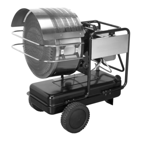
2.1. Paraffin/diesel heaters with low-fume heat output. Specially constructed stainless steel combustion chamber is vertically vented through
a flue, dramatically reducing the amount of fumes emitted through the hot air nozzle of the heater. Fully specified with safety cut-out and
incorporating a fuel filter for clean, reliable operation. Fitted with an industrial pump for high thermal efficiency and output. Optional nose
cone, Model No.ABNC04 together with standard ducting allows heat to be routed where required with the heater up to eight metres away.
Ideal for heating marquees, village halls and other public areas. Heaters may be controlled by optional remote thermostat, Model No. ABT04.
2. INTRODUCTION & SPECIFICATIONS
2.2. Specifications
Model: AB125HE AB180HE
Output Btu/hr / kW: . . . . . . . . . . 125,215/36.4 . . 180,900/52.6
Tank capacity (ltr): . . . . . . . . . . . . . . . . . . . 51 . . . . . . . . . . 51
Fuel oil: . . . . . . . . . . . . . . . . . Paraffin/Diesel . Paraffin/Diesel
Electrical input: . . . . . . . . . . . . . . . . 230V 5A . . . . . . 230V 5A
Approx. hours operation per filling: . . . . . . 15 . . . . . . . . . . 10
Transport wheels: . . . . . . . . . . . . . . . . . . Yes. . . . . . . . . . Yes
Air flow (cfm): . . . . . . . . . . . . . . . . . . . . 1180. . . . . . . . . 1475
Model: AB125HE AB180HE
Automatic shut-off: . . . . . . . . . . . . . . . . . Yes. . . . . . . . . . Yes
Heated volume (ft3): . . . . . . . . . . . . . . 31300. . . . . . . . 45225
Heated volume (m3): . . . . . . . . . . . . . . . . 885. . . . . . . . . 1280
Flue diameter (mm): . . . . . . . . . . . . . . . . 150 . . . . . . . . . 150
Net weight (kg): . . . . . . . . . . . . . . . . . . . . 70 . . . . . . . . . . 76
Quality standard: . . . . . . . . . . . . . . CE Norm . . . . . CE Norm
3. INSTALLATION
4. OPERATION
4.1 Start-up:
4.1.1 The heaters are factory set to operate without a room thermostat.
4.1.2 If you wish to use a room (remote) thermostat, you may purchase one from your authorised Sealey dealer, model No. ABT04. Install the
thermostat by removing the socket cover (fig 5.1) and inserting the
thermostat plug into the socket.
4.1.3 Fill the tank with the correct fuel.
4.1.4 Plug into a mains socket (230V ~ 50Hz single phase) -
The green light indicates that the heater has power. (See fig 5.4)
(THE HEATER MUST BE EARTHED.)
4.1.5 If a thermostat is used, set it to maximum.
4.1.6 Turn the switch to the ON position. (See fig 5.3)
4.1.7 Set the desired temperature on the thermostat.
4.2 Reset after operation of the safety thermostats:
4.2.1 The heater is equipped with a reset button. When the heater locks out,
the red light on the push button (fig 5.2) is illuminated. When this
occurs, push the reset button to restart the heater.
4.2.2 The heater also incorporates a manual reset safety thermostat fixed in contact with the combustion chamber. This can be accessed via the
inspection hatch. To reset this thermostat, unplug the heater, open the inspection hatch and push the reset button on the thermostat body.
4.3 Shut down:
Turn the main switch to OFF to shut off the flame. The fan will continue rotating for approx 1min 45sec to cool the heater down. The fan
motor will automatically stop at the end of the aftercooling time, then the unit can be disconnected from the mains.
pWARNING! NEVER disconnect the supply plug to stop the heater whilst in operation. Without the operation of the aftercooling
fan, the intense heat could damage components within the machine.
fig.1
fig.2
fig.3 fig.4
fig.5
AB125HE & AB180HE - 1 - 290604
3.1. Assembly of wheels and foot.
Assemble the wheels and foot to the heater as indicated in fig.1
using the fixings provided.
3.2. Ventilation.
pWARNING! Only use the heater in well ventilated areas.
Ensure a minimum volume of air of 10m3/kW power and a
continuous natural air circulation through windows and doors. For
the most efficient operation provide at least 80m3/h air flow from
outside. If the operating area has no direct access to clean fresh
air we recommend you run a large gauge duct from the outside
of the building to the inlet of the heater in order to provide a clean
air intake. Ensure that the duct is laid so as to not compromise
safety. Careful consideration must also be given to the placing of
the heater to provide safe and comfortable heating.
3.3. Flue connection.
For indoor use this heater must be connected to a flue pipe to
vent exhaust gases outside. The heater can only be operated
without a flue when it is outside. Connect the heater to a chimney
or to an exhaust duct. To get a proper draught (at least 0,1 mbar)
in the chimney the exhaust gas path must rise as much as
possible vertically. Avoid any elbows and bends in the first part of
the exhaust ducts for at least 3 m. Avoid horizontal sections and
ensure that any subsequent bends are smooth. See fig.2 for flue
installation dos and donts.
If a room thermostat is used, set maximum temperature on it. Turn
switch to position "ON".
Set the desired temperature on room thermostat.
3.4. Ducting of heated air.
pUsing optional nose cone, Model No.ABNC04 (see fig.3) together
with standard ducting allows heat to be routed where required with
the heater up to eight metres away. Ideal for heating marquees,
village halls and other public areas. Heaters may be controlled by
optional remote thermostat, Model No. ABT04. (see fig.4)

5. MAINTENANCE
5.1 Maintenance should only be carried out by qualified personnel.
5.2 Before carrying out any form of maintenance, ensure the heater is not connected to the power supply.
5.3 The heater must be thoroughly inspected and cleaned once a year to ensure efficient combustion and long life, however specific parts of
the heater (list to follow) should be cleaned more regularly to ensure high performance:
a) The oil spraying nozzle and associated filter, b) The oil pump filter,
c) The main fuel filter cartridge, d) The ignition electrodes,
e) The inside of the appliance, using compressed air, f) The fan blades,
g) The flame sensor with a mild detergent.
5.4 Periodically check cables and electrical connections. 5.5 Check the oil filter and replace if necessary.
6. TROUBLESHOOTING
7. WIRING DIAGRAM
TROUBLE CAUSE SOLUTION
Heater does not start No power Check main distribution board and power supply line.
Faulty cable/connections Check/have cable replaced by a qualified electrician.
Burnt fuse Check and replace if required.
Room thermostat set too low Set room thermostat on a higher temperature.
Thermostat socket cap not inserted Insert cap into the thermostat socket.
The safety thermostat has been activated Reset the safety thermostat.
Heater starts, flame does not Dirty or faulty flame sensor Clean or replace.
ignite and then heater locks out Faulty burner control unit Contact your authorised Sealey dealer for advice/repairs.
Clogged nozzle Clean or replace.
Flame sensor receives an external light signal Check for external lights (sun, lamps, etc).
during ignition sequence
No fuel Fill tank.
Ignition fault, dirty or incorrectly spaced electrodes Clean electrodes, contact Sealey dealer if required.
Heater starts, but combustion is Dirty or blocked nozzle Clean or replace.
not good Clogged filters Clean or replace.
Leaks in fuel circuit Check and if necessary, replace.
Oil pump provides low pressure Contact your authorised Sealey dealer.
Insufficient combustion air Wrong air lock setting.
Insufficient ventilation air Contact your authorised Sealey dealer.
Heater stops due to safety The appliance has overheated Contact your authorised Sealey dealer.
thermostat Faulty safety thermostat
8. DECLARATION OF CONFORMITY
Declaration of Conformity We, the sole importer into the UK, declare that the products listed below are in
conformity with the following standards and directives.
For Jack Sealey Ltd. Sole importer into the UK of Sealey Power Products.
21st June 2004
PARAFFIN SPACE HEATERS
AB125HE & AB180HE
98/37/EC Machinery Directive
73/23/EEC Low Voltage Directive
89/336/EEC EMC Directive
93/68/EEC CE Marking Directive
Signed by Mark Sweetman
The construction files for these products are held by the manufacturer and may be
inspected, by a national authority, upon request to Jack Sealey Ltd.
AB125HE & AB180HE - 1 - 290604
KEY
EV Fuel Solenoid Valve
TR Ignition Transformer
M Motor
SL Warning Lamp
TS Safety Thermostat
FS Fuse
FC Flame Sensor
PL Reset Button
IN Switch
TH Room Thermostat (Optional)
FR Heated Filter (Optional)
This manual suits for next models
1
Table of contents
Other Sealey Heater manuals

Sealey
Sealey IRC153.V2 User manual

Sealey
Sealey EH2001 User manual

Sealey
Sealey CD2005.V2 User manual

Sealey
Sealey CD2013.V2 User manual

Sealey
Sealey IWMH2000R User manual

Sealey
Sealey IR14.V2 User manual

Sealey
Sealey IRS153.V5 User manual

Sealey
Sealey IRC153110V User manual

Sealey
Sealey PEH9001 User manual

Sealey
Sealey IRC153.V4 User manual

Sealey
Sealey IR33 User manual

Sealey
Sealey ABI1000 User manual

Sealey
Sealey LP451R User manual

Sealey
Sealey PEH5001 User manual

Sealey
Sealey AB1500Q User manual

Sealey
Sealey EH9001 User manual

Sealey
Sealey EH2000 User manual

Sealey
Sealey LP370 User manual

Sealey
Sealey CD2005T.V3 User manual

Sealey
Sealey RD1500.V6 User manual