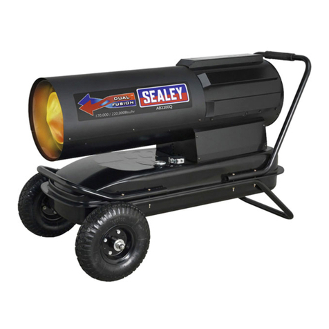
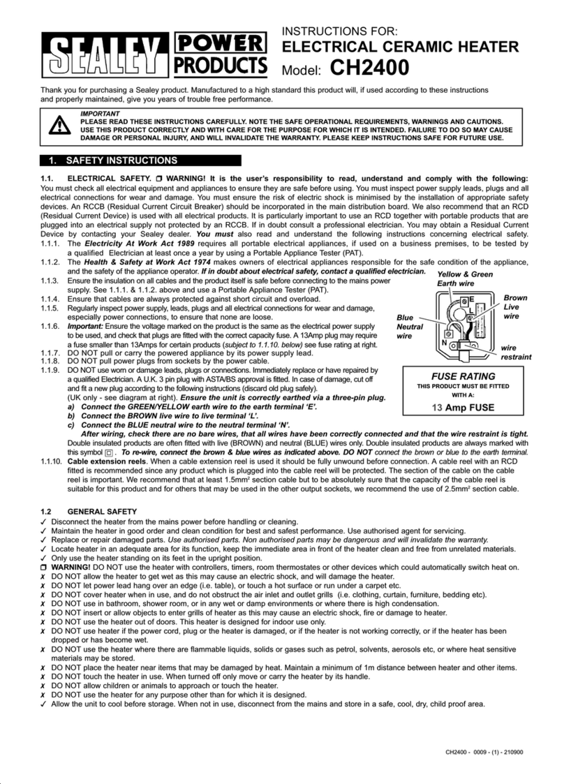
Sealey AB708.V2 User manual

SPACE WARMER PARAFFIN / KEROSENE /
DIESEL HEATERS
MODEL NO: AB708.V2, AB7081.V2
Thank you for purchasing a Sealey product. Manufactured to a high standard, this product will, if used according to these
instructions, and properly maintained, give you years of trouble free performance.
1. SAFETY
1.1. ELECTRICAL SAFETY
WARNING! It is the responsibility of the owner and the operator to read, understand and comply with the following:
You must check all electrical products, before use, to ensure that they are safe. You must inspect power cables, plugs, sockets
and any other connectors for wear or damage. You must ensure that the risk of electric shock is minimised by the installation of
appropriate safety devices. A Residual Current Circuit Breaker (RCCB) should be incorporated in the main distribution board. You
must also read and understand the following instructions concerning electrical safety.
9Ensure that cables are always protected against short circuit and overload.
9Regularly inspect power supply cables and plugs for wear or damage and check all connections
to ensure that none are loose.
9Ensure that the voltage marked on the appliance matches the power supply to be
usedandthattheplugisttedwiththecorrectfuse-seefuseratingatright.
8DO NOT use worn or damaged cables, plugs or connectors. Have any faulty item repaired or
replaced immediately by a competent electrician.
9It is recommended that this heater is wired directly to a fused isolator switch. If, however, a plug
istted,thefollowingapplies:
9Fit a new plug according to the following instructions (UK only).
a) Connect the GREEN/YELLOW earth wire to the earth terminal ‘E’.
b) Connect the BROWN live wire to the live terminal ‘L’.
c) Connect the BLUE neutral wire to the neutral terminal ‘N’.
d) After wiring, check that there are no bare wires, that all wires have been correctly connected,
that the cable restraint is tight.
1.2. GENERAL SAFETY
▲DANGER! Risk of carbon monoxide poisoning. Failure to provide proper ventilation could result in serious illness or death.
9Check that the heater is in sound condition and good working order. Take immediate action to repair or replace damaged parts.
9Use recommended parts only. Unapproved parts may be dangerous and will invalidate the warranty.
9Only use clean paraffin, kerosene or diesel (NOT BIO-DIESEL) to fuel your heater, in accordance with instructions contained in this
manual
WARNING! Only use heater in well ventilated areas. Ensure continuous ventilation from outside of the building is provided to the
heater operating area. Allow at least 3ft² opening/100000Btu/hr output.
9Keep the front of the heater a minimum of 2.4 metres and the rear and sides1.2 metres from any combustible materials (i.e. wooden
items, cloth, plastics, paper,tarpaulins or similar enclosure materials).
9Only operate on a level and stable surface.
WARNING! DO NOTusetheheaternearammablematerial,liquids,solids,gasesorcompressedgascylinders.
8DO NOT use the heater in closed rooms, living areas, basements or below ground level.
8DO NOT allow untrained persons to operate the heater and DO NOT operate the heater without the cover.
8DO NOT move or handle the heater when hot.
8DO NOT leave the heater unattended when in use. Switch the heater off and unplug from the mains before leaving work area.
8DO NOTllthefueltankwhilsttheheaterisrunningorstillhot.
8DO NOToverllthefuelcontainer.Wipeupanyspiltfuelimmediately.
8DO NOT obstruct the air inlet (rear) and air outlet (front) of the heater. DO NOT use duct work in front or at the rear of the heater.
8DO NOT look into the exhaust end of the heater.
8DO NOT allow children or animals near the heater when in use, or while hot.
WARNING! RISK OF ELECTRIC SHOCK. DO NOT expose the heater to water spray, rain, dripping water or wind.
8DO NOToperatetheheaterwhenyouaretiredorundertheinuenceofalcohol,drugsorintoxicatingmedication.
8DO NOTtouchtheheateroutletordomewhenrstswitchedoffastheseareveryhotandwilltaketimetocool.
9Ensure that the heater is correctly turned off when not in use and store in a safe, dry area, out of reach of children.
8DO NOT unplug the heater to switch it off. Use the ON/OFF switch.
WARNING! Improper maintenance can lead to poor combustion and soot production
NOTE: This appliance is not intended for persons (including children) with reduced physical, sensory or mental capabilities, or lack of
experience and knowledge, unless they have been given supervision or instruction concerning use of the appliance by a person
responsible for their safety. Children should be supervised to ensure that they do not play with the appliance.
Recommended fuse rating
13 Amp
Original Language Version
© Jack Sealey Limited
Refer to
instructions Warning!
AB708.V2, AB7081.V2 Issue:8 (ERP) 12/07/19
Warning!
Hot surfaces
This product is not suitable for primary heating purposes
Warning!
automatic
start-up
IMPORTANT: PLEASE READ THESE INSTRUCTIONS CAREFULLY. NOTE THE SAFE OPERATIONAL REQUIREMENTS, WARNINGS & CAUTIONS. USE
THE PRODUCT CORRECTLY AND WITH CARE FOR THE PURPOSE FOR WHICH IT IS INTENDED. FAILURE TO DO SO MAY CAUSE DAMAGE AND/OR
PERSONAL INJURY AND WILL INVALIDATE THE WARRANTY. KEEP THESE INSTRUCTIONS SAFE FOR FUTURE USE.

2. INTRODUCTION
OurrangeofParafn/Kerosene/DieselHeatersrepresentsexcellentvalue.Workshoptriedandtested.Therangeincludestwoeconomy
portable units, Model No’s AB458 and AB708, which are both supplied without wheels. All except Model No. AB458 have an adjustable
thermostat(°C).ModelNo’sAB1008andabovearettedwithdigitalroomtemperature(°C)display/errorcodereadoutandspareparts
storagecompartment.Provenpumpsystemshandleeitherparafn,keroseneordieselwithonlyminoradjustmentofaircompressor.All
modelsarettedwithfueltankgaugeandheavy-dutyfuelcap.ModelNo’sAB1008,AB1258,AB1758andAB2158featurecablestorageon
handle.ModelNo’sAB7081andabovearesuppliedwithheavy-dutypneumaticwheels.
WARNING! This heater is not suitable for use with Bio-Diesel; use of Bio-Diesel will damage the lter and seals. Damage
caused by use of Bio-Diesel will not be covered by warranty.
3. SPECIFICATION
MODEL AB7081.V2 AB708.V2
BTU/hr Output (kW) 70000 (20.5) 70000 (20.5)
Fuel Oil Parafn/Kerosene
/ Diesel Parafn/Kerosene
/ Diesel
Maximum operating hours 9hr 9hr
Fuel Tank Capacity (Litres) 19.0 19.0
Electrical Input 230V 5A 230V 5A
Power Cable (mtr) 2.1 2.1
Automatic shut off Yes Yes
Net (Kg) 15.3 12.7
Transport wheels Yes No
Airow(cfm) 240 240
Pump pressure PSI ±10% 4.0 4.0
Heated Volume 13600ft³/385mtr³ 13600ft³/385mtr³
Consumption (Litre per hour) 2.0 2.0
4. ASSEMBLY
Unpack the heater and check contents. Should there be any damaged or missing parts
contact your Sealey stockist immediately.
4.1. ASSEMBLING FRAME AND WHEELS FOR AB7081
4.1.1. Slide axle through wheel support frame, slide a bushing and flat washer (A) to each end of
the axle.
4.1.2. Install wheels with valve stem on the outside, slide flat washer (B) onto the axle and then
insert a cotter pin and bend the legs of the pin with pliers to secure. Snap the wheel caps
onto the flat washer (B).
4.1.3. Place heater on wheel support frame ensuring that the air inlet is by the wheels and place
the heater onto the frame lining up the holes on the fuel tank flange with holes
on the wheel support frame.
4.1.4. Place handle on fuel tank flange and line up with the wheel support frame fixing holes.
Insert bolts provided through the fuel tank flange and both frames and secure finger tight
only with nuts and washers provided.
g.1 g.2
g.3
g.4
Original Language Version
© Jack Sealey Limited AB708.V2, AB7081.V2 Issue:8 (ERP) 12/07/19

4.1.5. When assembly is complete, securely tighten all nuts.
WARNING! DO NOT use AB7081 without the support frame fully assembled.
4.2. ASSEMBLING TOP HANDLE
4.2.1. Align the holes in the handle with the holes in the upper housing. Insert and tighten the screws provided with a cross headed screwdriver
as shown in fig.4.
4.3. ASSEMBLING THE CABLE TIDIES FOR AB708
4.3.1. Mount the cable tidies onto either end of the panel on the other side of the heater from the main control panel, as shown in fig.1. Hook
the two tabs on each moulding into the holes at either end of the panel. The tongue on each moulding should now be lying on the face of
the panel. Secure each moulding in place with a screw through the tongue and into the ready made holes in the panel.
5. OPERATING CONDITIONS
5.1. PARAFFIN, KEROSENE AND DIESEL FUEL USAGE
These AB heaters are factory adjusted to give the most efficient burn on paraffin and kerosene but will also burn diesel. Note that
paraffin and kerosene will tend to burn more cleanly than diesel. Care should be taken to provide at least the minimum amount of
ventilation recommended when burning diesel.
WARNING! Never use any other fuel such as petrol, benzene, alcohol, camping stove fuel, paint thinners or other oil
compounds. USE OF THESE VOLATILE FUELS MAY CAUSE A FIRE OR EXPLOSION.
5.2. STORAGE OF FUEL
Always store paraffin, kerosene and diesel in a well ventilated area well away from general living space. Do not store in direct sunlight
or near a source of heat or other source of ignition such as a torch or a portable generator. Do not use fuel that has been stored from
one season to the next as it may have deteriorated and will not burn properly in the heater. Store the fuel in a suitable container which
complieswithrequirementssetoutinlocalauthorityregulations.
5.3. FILLING THE FUEL TANK
Never fill the fuel tank indoors. Always fill the fuel tank outdoors on a level surface. Take note of the position of the fuel gauge whilst
filling the tank and do not overfill it. Never refill the tank whilst the heater is operating or is still hot.
5.4. VENTILATION REQUIREMENTS
Usethisheateronlyinawellventilatedarea.Youshouldprovideanopeningtotheoutsideairofatleasta3squarefeet(0.9M²)for
every 100,000 BTU/hr of heat output. Provide a larger opening if more than one heater is being used.
5.5. SIGHTING THE HEATER
Always install the heater so that it will not be directly exposed to water spray, rain, dripping water or wind. The heater should not be
placed near to any combustible materials. The minimum clearance from combustibles is 1.2m from the top of the heater, 1.2m from
the sides of the heater and 2.4m from the front of the heater. Never use the heater in spaces which contain products such as petrol,
solvents, paint thinners, dust particles, volatile or airborne combustibles, or any unknown chemicals.
WARNING! Air contaminants taken into the heater may affect the heat output, damage the unit and may cause health
problems. Example: Bodyshop filler dust / paint overspray will damage the motor bearing, clog the filter and pump and
contaminate the combustion chamber causing flame flutter and health hazards. Please note that any parts damaged by filler
dust / paint overspray will not be covered by warranty. Additionally, a cleaning charge will be made for any heaters damaged
by filler dust.
6. THEORY OF OPERATION
6.1. FUEL SYSTEM.Theheaterisequippedwithanairpumpthatoperatesofftheelectricmotor.Thepumpforcesairthroughtheairline
connected to the fuel tank, drawing fuel to the nozzle in the burning head. Air also passes through the nozzle where it mixes with the
fuel and is sprayed into the combustion chamber in a fine mist.
6.2. QUICK FIRE IGNITION. A transformer sends high voltage to a two pronged spark plug. The resultant spark ignites the fuel air mixture
as it is sprayed into the combustion chamber.
6.3. AIR SYSTEM. Afan is turned by the heavy duty motor which forces air around and into the combustion chamber, where it is super
heated and forced out of the front of the chamber.
6.4. TEMPERATURE LIMIT CONTROL.Theheaterisequippedwithatemperaturelimitcontroldesignedtoturntheheateroffshouldthe
internaltemperaturerisetoanunsafelevel.Ifthisdeviceactivatesandturnsyourheateroff,itmayrequireservicing.Oncethe
temperature falls below the reset temperature, you will be able to restart the heater.
6.5. ELECTRICAL SYSTEM PROTECTION. The heater’s electrical system is protected by a circuit breaker that protects the systems
components from damage. If the heater ceases to work, check the fuse first and replace if necessary. See maintenance section 8.6.
6.6. FLAME SENSOR. The heater uses a photocell to ‘see’ the flame in the combustion chamber. Should the flame extinguish, the sensor
will cut off the electrical current and the heater will shut down.
7. OPERATION
7.1. TO START THE HEATER
7.1.1. Fill the tank with fuel until the fuel gauge points to “F”. Do not overfill.
7.1.2. Ensure that the fuel cap is replaced and fully tightened down.
7.1.3. Unwind the mains cable from cable tidies and plug the heater into the mains power
supply.
7.1.4. Turn the thermostat control knob to the desired temperature. The range is from 40°F to
110°F. (4.4°C to 43°C)
7.1.5. Push the power switch to the ON position.
7.1.6. The power lamp will illuminate and the heater will start. The heater will run up to
thepre-settemperatureandthenswitchonandoffautomaticallytomaintainthepre-set
temperature.
7.1.7. If the heater will not start, the temperature may be set too low. Turn the temperature
control knob to a higher setting until the heater fires. If the heater still does not start turn the power switch to OFF, then turn back ON. If
the heater still does not fire refer to the troubleshooting guide.
NOTE: The electrical components of these heaters are protected by a fuse mounted on the PC board. If the heater will not fire, check this fuse
first and replace if necessary. Also check that the proper voltage is being supplied to the heater.
g.5
Original Language Version
© Jack Sealey Limited AB708.V2, AB7081.V2 Issue:8 (ERP) 12/07/19
7.2. TO STOP THE HEATER.
7.2.1. Turn the power switch to OFF and disconnect the mains power supply. NEVER SHUT DOWN THE HEATER BY PULLING OUT THE
PLUG. DO NOT touch the heater outlet as this will remain hot for some time. Store in a dry, safe, childproof area.
7.3. TO RESTART THE HEATER.
7.3.1. Wait ten seconds after shutting off the heater.
7.3.2. Turn the power switch to ON.
8. MAINTENANCE
WARNING! MAINTENANCE MUST ONLY BE UNDERTAKEN BY A QUALIFIED PERSON. WE STRONGLY RECOMMEND
THAT ALL SERVICING IS DONE BY YOUR LOCAL SERVICE AGENT.
8.1. MAINTENANCE SCHEDULE
WARNING! Never attempt to service the heater whilst it is still hot, wait until it has cooled enough to touch. Unplug the heater
from the mains supply before servicing.
Use only genuine Sealey replacement parts. Use of alternative/third party components will cause unsafe operation and will invalidate
your warranty.
8.2. FUEL TANK
Clean out the fuel tank every 200 hours of operation or as needed. Flush out with paraffin, kerosene or diesel fuel depending on which
fuelyouareusing.Donotuseanyotherliquidforthisoperation.
8.3. AIR FILTERS (See fig.6)
The air intake filter should be replaced or washed with soap and water and thoroughly dried every 500 hours of operation or less, depending
on the conditions of operation.
The air output filter and lint filtershouldbereplacedevery500hoursormorefrequentlydependingonconditionsofuse.
8.4. FAN BLADES (See fig.7)
The fan blades should be cleaned at least once per heating season, depending on conditions in the area of use. Remove all
accumulated dust and dirt with a damp cloth, taking care not to bend any of the fan blades. Dry the fan blades thoroughly before
restarting the heater. For fan removal see fig.7.
8.5. NOZZLE (See fig.8)
The nozzle should be cleaned at least once per heating season. Use of contaminated fuel will make it necessary to clean the nozzle
morefrequently.Tocleandirtfromthenozzle,blowcompressedairthroughthefrontofthenozzle.Itmaybenecessarytosoakthe
nozzle in paraffin, kerosene first in order to loosen any dirt particles.
8.6. SPARK PLUG (See fig.9)
Cleanandre-gapthesparkplugevery600hoursofoperation,orreplaceifneeded.Afterremovingthesparkplug,cleantheterminals
withawirebrush.Re-gaptheterminalsto3.5mm(0.140”).
g.6 g.7
g.8 g.9
g.10
g.11
Original Language Version
© Jack Sealey Limited AB708.V2, AB7081.V2 Issue:8 (ERP) 12/07/19
8.7. PHOTO CELL (See figs.10 & 11)
The photocell should be cleaned at least once per heating season or more depending on conditions of use. Use a cotton swab dipped in
water or alcohol to clean the lens of the photocell. The positioning of the photocell is critical to its correct operation. See fig.11 for the
correct installation.
8.8. FUEL FILTER (See fig.12)
The fuel filter should be cleaned at least twice per heating season by rinsing it in clean paraffin or kerosene. Use of contaminated fuel
willmakeitnecessarytocleanthefiltermorefrequently.Toremovethefilterfirstsqueezethelegsofthefuellineclipandmoveitupthe
fuel line.Easethefuellinefromoffthefilterhead.Turnthehexagonalheadofthefilter90°anti-clockwiseandease it upwards and out
of the tank.
8.9. PUMP PRESSURE ADJUSTMENT (See fig.13)
For the efficient burning of fuel and optimum heat output the pumps on these heaters are designed to run at the specific pressures
indicated below.
MODEL No: PUMP PRESSURE
AB708 4PSI ±10%
AB7081 4PSI ±10%
Periodicallycheckthepumppressurebyreferringtothepressuregaugewithinthereargrille.Ifadjustmentisrequiredturntheadjusting
screw located to the right of the gauge using a slotted screwdriver
as shown in fig.13.
8.10. FUSE REPLACEMENT (See fig.14)
NOTE: This is a fuse protected heater.
If your heater fails to ignite check the fuse as shown in fig.14 before
contacting your local service agent.
WARNING! Unplug the heater from the mains power supply before
attempting any maintenance work.
8.10.1. Remove the control panel screws using a medium phillips screwdriver
and lift off the side panel to reveal the printed circuit board.
8.10.2. Disconnect switch wires from the power switch.
8.10.3. Remove fuse from holder as shown below.
8.10.4. Replace fuse with one of the same specification.
WARNING! Do not substitute the fuse with one of a higher or lower
current rating as this may result in a fire hazard.
8.10.5. Reconnect switch wires to the power switch.
8.10.6. Replace side panel.
8.11. LONG TERM STORAGE
If the heater is to be stored for a long period of time, drain the fuel
through the fuel cap opening. Rinse and swirl a small amount of fuel
within the tank and then empty it fully. When you come to use the
heater again do not use old fuel which has been stored from the
previous season. Use of old fuel can damage your heater.
Although our heaters operate with diesel fuel, when the temperature is
below0°Cdieseladditivesarerequiredtomaintainthediesel’sviscosity.
Typically diesel can cloud in freezing conditions and will start to gel. You will
need additives for your fuel in these conditions.
Kerosene/Parafndoesnotstarttogeluntiltheambienttemperatureisaround
-40°C.
g.12
g.14
g.13
Original Language Version
© Jack Sealey Limited AB708.V2, AB7081.V2 Issue:8 (ERP) 12/07/19

9. TROUBLESHOOTING
Problem Possible Cause Solution
Heaterres,butmainPCBshuts
heater off after a short period of time.
Lampisickering.
1. Incorrect pump pressure 1. Adjust pump pressure
2.Dirtyinput,outputorlintlter 2. Clean/replace Air Filter
3. Dirty Fuel Filter 3. Clean/replace Fuel Filter
4. Nozzle is dirty 4. Clean/replace Nozzle
5. Photocell lens is dirty 5. Clean/replace Photocell
6. Photocell not installed properly 6. Adjust Photocell position
7. Photocell Defective 7. Replace Photocell
8. Improper electrical connection between Main
PCB and Photocell 8. Check wiring connections (See Wiring
Diagram)
9. Ambient temperature too low for fuel type 9. Change fuel type
Heater will not operate or motor runs for a
shorttime.Lampickers.
1.Noparafninfueltank 1.Filltankwithfreshparafn
2. Incorrect pump pressure 2. Adjust pump pressure
3. Corroded Spark Plug or incorrect gap 3. Clean/adjust/replace spark plug
4. Dirty Fuel Filter 4. Clean/replace Fuel Filter
5. Dirty Nozzle 5. Clean/replace Nozzle
6. Moisture in Fuel/Fuel Tank 6.Rinseoutfueltankwithfreshparafn
7. Faulty electrical connection 7. Inspect all electrical connections
8. Ignitor Wire not connected to Spark Plug 8.Re-attachIgnitorWiretoSparkPlug
9. Defective Ignitor 9. Replace Ignitor
Fan does not operate when heater is
plugged in and Power Switch is in the
“ON”position.Thelampisickeringoron.
1. Thermostat is set too low 1. Rotate Thermostat to a higher setting
2. Broken electrical connection between Main
PCB and motor 2. Inspect all electrical connections
Lampickering. 1. Thermostat Switch has failed 1. Replace Thermostat Switch
Poor Combustion. 1. Flames extending beyond heater 1. Decrease Pump Pressure
2. Low heat output 2. Increase Pump Pressure
Heater does not turn on and the lamp is
not lit. 1. Temperature limit sensor has overheated 1. Push Power Switch to “OFF” and allow heater
to cool for 10 minutes. Push Power Switch
back “ON”
2. No electrical power 2. Check power cable and extension cable
connections. Test power supply.
3. Fuse Blown 3. Check/replace Fuse
4. Faulty connection between Temperature Limit
Sensor and PCB 4. Inspect all electrical connections
Sealey Group, Kempson Way, Suffolk Business Park, Bury St Edmunds, Suffolk. IP32 7AR
01284 757500 01284 703534 sales@sealey.co.uk www.sealey.co.uk
ENVIRONMENT PROTECTION
Recycle unwanted materials instead of disposing of them as waste. All tools, accessories and packaging should be sorted, taken to
a recycling centre and disposed of in a manner which is compatible with the environment. When the product becomes completely
unserviceableandrequiresdisposal,drainanyfluids(ifapplicable)intoapprovedcontainersanddisposeoftheproductandfluids
according to local regulations.
WEEE REGULATIONS
DisposeofthisproductattheendofitsworkinglifeincompliancewiththeEUDirectiveonWasteElectricalandElectronicEquipment
(WEEE).Whentheproductisnolongerrequired,itmustbedisposedofinanenvironmentallyprotectiveway.Contactyourlocalsolid
waste authority for recycling information.
Note: It is our policy to continually improve products and as such we reserve the right to alter data, specifications and component parts without prior
notice. Pleasenotethatotherversionsofthisproductareavailable.Ifyourequiredocumentationforalternativeversions,pleaseemailorcall
our technical team on technical@sealey.co.uk or 01284 757505.
Important: No Liability is accepted for incorrect use of this product.
Warranty:Guaranteeis12monthsfrompurchasedate,proofofwhichisrequiredforanyclaim.
Original Language Version
© Jack Sealey Limited AB708.V2, AB7081.V2 Issue:8 (ERP) 12/07/19
Model identier(s):
Indirect heating functionality: Yes No
Direct heat output: (kW) Indirect heat output: (kW)
Fuel
Select fuel type: Gaseous Liquid Specify: [mg/kWhinput] (GCV)
Item Symbol Value Unit Item Symbol Value Unit
Heatoutput Usefuleciency(NCV)
Nominal heat output Pnom kW Useful eciency at nominal ῃth,nom %
heat output
Minimum heat output (indicative)* Pmin kW Useful eciency at minimum ῃth,min %
heat output (indicative)*
Auxiliaryelectricityconsumption Typeofheatoutput/roomtemperaturecontrol(selectone)
At nominal heat output elmax kW Single stage heat output, no room Yes No
temperature control
At minimum heat output elmin
kW Two or more manual stages, no room Yes No
temperature control
In standby mode elSB kW With mechanical thermostat room Yes No
temperature control
With electronic room temperature control Yes No
plus day timer
With electronic room temperature control Yes No
plus week timer
Othercontroloptions(multipleselectionspossible)
Room temperature control, with presence Yes No
detection
Room temperature control, with open Yes No
window detection
With distance control option Yes No
With adaptive start control Yes No
With working time limitation Yes No
With black bulb sensor Yes No
Informationrequirementsforgaseous/liquidfuellocalspaceheaters
Theseasonalspaceheatingenergyeciencyƞs
Item Symbol Value Unit
The seasonal space heating Energy efficiency in active mode ƞs,on %
The seasonal space heating energy efficiency ƞs ƞs%
Energyefficiencyclasses
Contact details: Sealey Group, Kempson Way, Suolk Business Park, Bury St Edmunds, Suolk, IP32 7AR. www.sealey.co.uk
ERP Table 1
Space heating emissions
NOx nitrogen oxides
Permanentpilotamepowerrequirement
Pilot ame power required Ppilot
kW
(if applicable)*
* Enter gure or NA
19.8
N/A N/A
0.323
N/A
N/A
N/A
90.1
112.37
90.1
A
Diesel
AB708.V2
20.5 N/A
100
v1
19.8
N/A N/A
0.323
N/A
N/A
N/A
90.1
112.37
90.1
A
Diesel
AB708.V2
20.5 N/A
100
v1

Model identier(s):
Indirect heating functionality: Yes No
Direct heat output: (kW) Indirect heat output: (kW)
Fuel
Select fuel type: Gaseous Liquid Specify: [mg/kWhinput] (GCV)
Item Symbol Value Unit Item Symbol Value Unit
Heatoutput Usefuleciency(NCV)
Nominal heat output Pnom kW Useful eciency at nominal ῃth,nom %
heat output
Minimum heat output (indicative)* Pmin kW Useful eciency at minimum ῃth,min %
heat output (indicative)*
Auxiliaryelectricityconsumption Typeofheatoutput/roomtemperaturecontrol(selectone)
At nominal heat output elmax kW Single stage heat output, no room Yes No
temperature control
At minimum heat output elmin
kW Two or more manual stages, no room Yes No
temperature control
In standby mode elSB kW With mechanical thermostat room Yes No
temperature control
With electronic room temperature control Yes No
plus day timer
With electronic room temperature control Yes No
plus week timer
Othercontroloptions(multipleselectionspossible)
Room temperature control, with presence Yes No
detection
Room temperature control, with open Yes No
window detection
With distance control option Yes No
With adaptive start control Yes No
With working time limitation Yes No
With black bulb sensor Yes No
Informationrequirementsforgaseous/liquidfuellocalspaceheaters
Theseasonalspaceheatingenergyeciencyƞs
Item Symbol Value Unit
The seasonal space heating Energy efficiency in active mode ƞs,on %
The seasonal space heating energy efficiency ƞs ƞs%
Energyefficiencyclasses
Contact details: Sealey Group, Kempson Way, Suolk Business Park, Bury St Edmunds, Suolk, IP32 7AR. www.sealey.co.uk
ERP Table 1
Space heating emissions
NOx nitrogen oxides
Permanentpilotamepowerrequirement
Pilot ame power required Ppilot
kW
(if applicable)*
* Enter gure or NA
19.8
N/A N/A
0.323
N/A
N/A
N/A
90.1
112.37
90.1
A
Diesel
AB7081.V2
20.5 N/A
100
v1
19.8
N/A N/A
0.323
N/A
N/A
N/A
90.1
112.37
90.1
A
Diesel
AB7081.V2
20.5 N/A
100
v1
This manual suits for next models
2
Table of contents
Other Sealey Heater manuals

Sealey
Sealey IR40 User manual

Sealey
Sealey PEH2001 User manual

Sealey
Sealey CH4200 User manual

Sealey
Sealey FH2010 User manual

Sealey
Sealey PEH9001 User manual

Sealey
Sealey IRC1428 User manual

Sealey
Sealey ABI1000 User manual

Sealey
Sealey RD800 User manual

Sealey
Sealey IWMH2003RC.V2 User manual

Sealey
Sealey Power Products CD2000 User manual

Sealey
Sealey AB458.V3 User manual

Sealey
Sealey AB1008.V2 User manual

Sealey
Sealey LP290 User manual

Sealey
Sealey IWMH2003RC User manual

Sealey
Sealey PEH5001 User manual

Sealey
Sealey PEH3001.V2 User manual

Sealey
Sealey EH2000 User manual

Sealey
Sealey LP13.V4 User manual

Sealey
Sealey Space Warmer LP13.V3 User manual

Sealey
Sealey LP225 User manual