Sealey PP35.V2 User manual

INSTRUCTIONS FOR
PLASMA INVERTER
PP35.V2
MODEL No:
Original Language Version PP35.V2 Issue: 3 - 15/05/12

2. SAFETY INSTRUCTIONS
2.1. ELECTRICAL SAFETY
WARNING! Electrical installation of the plasma cutting unit must be carried out by a qualified electrician. Make sure that
power supply cable is correctly connected to earth. It is the owner’s responsibility to read, understand and comply with the
following:
You must check all electrical equipment and appliances to ensure that they are safe before using. You must inspect power supply
leads, plugs and all electrical connections for wear and damage. You must ensure that the risk of electric shock is minimised by the
installation of appropriate safety devices. An RCCB (Residual Current Circuit Breaker) should be incorporated in the main distribution
board. We also recommend that an RCD (Residual Current Device) is used with all electrical products. It is particularly important to
use an RCD with portable products that are plugged into an electrical supply not protected by an RCCB. If in doubt consult a qualified
electrician. You may obtain a Residual Current Device by contacting your Sealey dealer. You must also read and understand the
following instructions concerning electrical safety.
2.1.1. The Electricity At Work Act 1989 requires all portable electrical appliances, if used on business premises, to be tested by
a qualified electrician, using a Portable Appliance Tester (PAT), at least once a year.
2.1.2. The Health & Safety at Work Act 1974 makes owners of electrical appliances responsible for the safe condition of the appliance
and the safety of the appliance operator. If in any doubt about electrical safety, contact a qualified electrician.
2.1.3. Ensure that the insulation on all cables and the product itself is safe before connecting to the mains power supply. See 2.1.1. & 2.1.2.
above and use a Portable Appliance Tester.
2.1.4. Ensure that cables are always protected against short circuit and overload.
2.1.5. Regularly inspect power supply, leads, plugs and all electrical connections for wear or
damage and check power connections, to ensure that none is loose.
2.1.6. Important: Ensure that the voltage marked on the product is the same as the power supply
to be used and that the supply is adequately protected. See Supply Fuse, Section 1.
2.1.7. DO NOT pull or carry the cutter by the power supply lead or the output cables.
2.1.8. DO NOT pull plugs from sockets by the cable.
2.1.9. DO NOT use worn or damaged leads, plugs or connections. Immediately replace or have repaired by a qualified electrician.
2.1.10. This product will require more than a 13Amp electrical supply, so a plug is not fitted, it is a single phase machine and must be run
from a minimum 16Amp supply. To achieve maximum output this model will require a 30Amp fused supply. We recommend you
discuss the installation of an industrial round pin plug and socket with a qualified electrician.
Fit a plug according to the following instructions (UK only).
a) Connect the GREEN/YELLOW earth wire to the earth terminal ‘E’.
b) Connect the BROWN live wire to the live terminal ‘L’.
c) Connect the BLUE neutral wire to the neutral terminal ‘N’.
d) After wiring, check that there are no bare wires, that all wires have been correctly connected, that the cable outer insulation
extends beyond the cable restraint and that the restraint is tight.
Double insulated products, which are always marked with this symbol , are fitted with live (brown) and neutral (blue) wires only.
WARNING! Reminder, the electrical installation of the plasma cutting unit must only be carried out by a qualified electrician.
WARNING! Be very cautious if using a generator to power the inverter. The generator must be self regulating and stable with
regard to voltage, waveform and frequency. The output must be greater than the power consumption of the inverter. If any of
these requirements is not met the electronics within the inverter may be affected.
NOTE: The use of an unregulated generator may be dangerous and will invalidate the warranty.
WARNING! The inverter may produce voltage surges in the mains supply which can damage other sensitive equipment
(e.g. computers). To avoid this happening it is recommended that the inverter is connected to a power supply that does not feed
any sensitive equipment.
2.1.11. If an extension reel is used it should be as short as possible and fully unwound before connection. A reel with an RCD fitted is
preferred since any appliance plugged into it will be protected. The cable core section is important and should be at least 1.5mm²,
but to be absolutely sure that the capacity of the reel is suitable for this product and for others which may be used in the other output
sockets, we recommend the use of 2.5mm² section cable.
1.1. Introduction
Inverter power supply fitted with plasma cutter control circuitry. Inverter features three LED information panel including torch under-
voltage, air fault, general fault (thermostat, over/under-voltage, over-current) and power on. Supplied with plasma torch and earth
cable. Uses air to strike arc making it suitable for use near electrical equipment. Ideal for cutting steel, stainless, galvanized steel,
aluminium, copper and brass. Includes integral air filter and regulator unit with panel-mounted pressure gauge. IP23 Rated.
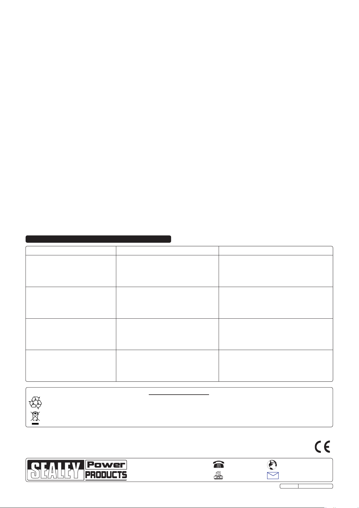
1.2. Specification:
Duty Cycle.............................. 30% @ 35A
Air Flow ......................................100ltr/min
Air Pressure ..................4-5 bar (58-72psi)
Supply ......................................230V - 1ph
Absorbed Power ...............................4 KW
Insulation Class....................................... H
Protection ........................................... IP23
Weight ...............................................7.7kg
Current Range.................................................. 7-40A
Max. Cutting Thickness ....................................12mm
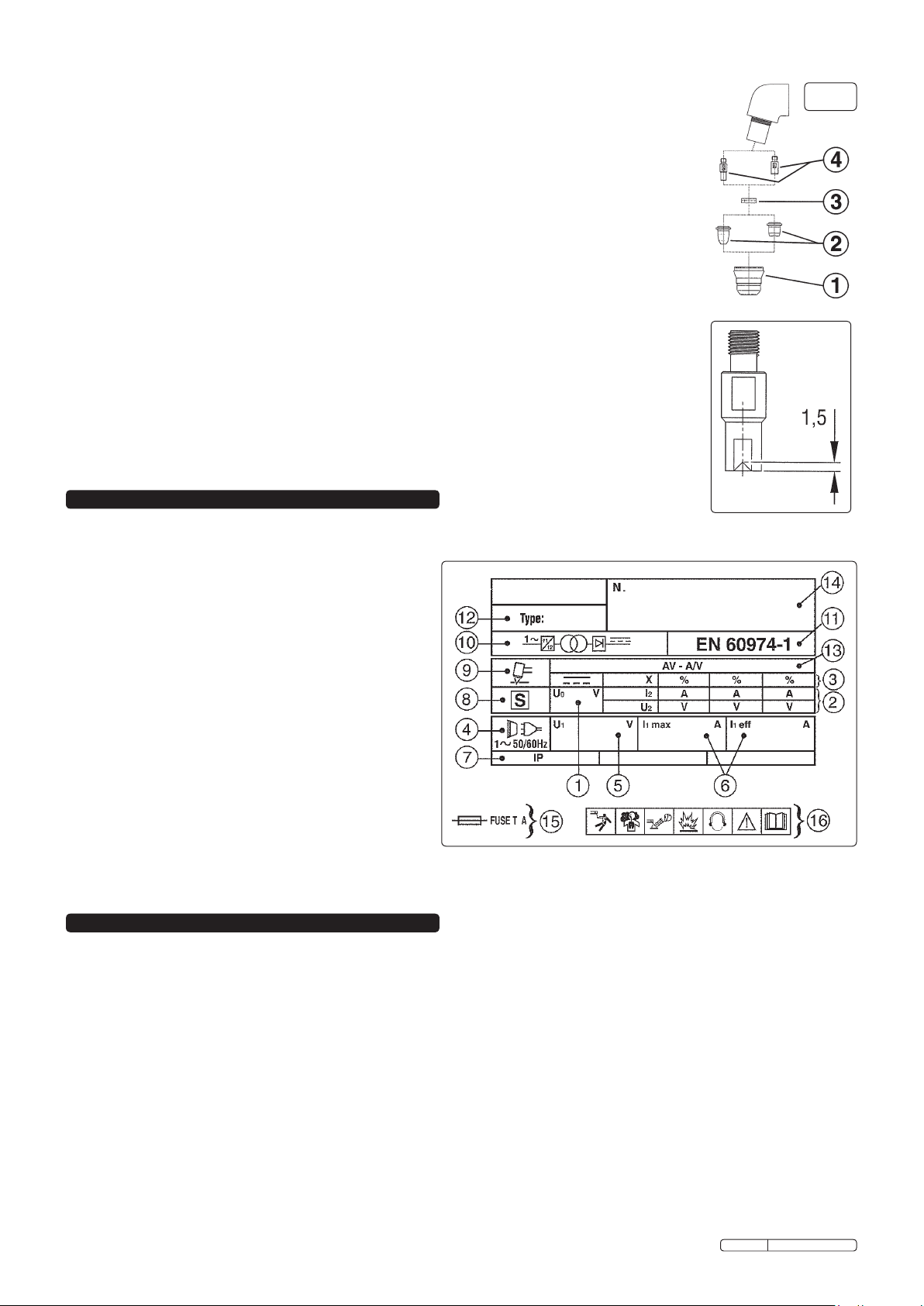
Torch:
Gas............................................. Dry compressed air
Air Pressure................................... 4-5 bar (58-72psi)
Cooling Flow Rate...................................... 100ltr/min
Striking System ........................................... Pilot Arc
Cutting Current ................................................. 7-40A
1. INTRODUCTION & SPECIFICATION
Original Language Version PP35.V2 Issue: 3 - 15/05/12
INSTRUCTIONS FOR:
PLASMA INVERTER
MODEL No: PP35.V2
Thank you for purchasing a Sealey plasma inverter. Manufactured to a high standard this product will, if used according to these instructions and properly
maintained, give you years of trouble free performance.
IMPORTANT: BEFORE USING THIS PRODUCT, PLEASE READ THE INSTRUCTIONS CAREFULLY. MAKE CAREFUL NOTE OF SAFETY INSTRUCTIONS, WARNINGS
AND CAUTIONS. THIS PRODUCT SHOULD ONLY BE USED FOR ITS INTENDED PURPOSE. FAILURE TO DO SO MAY CAUSE DAMAGE AND/OR PERSONAL NJURY
AND WILL INVALIDATE THE WARRANTY. RETAIN THESE INSTRUCTIONS FOR FUTURE USE.
230V 1ph
THE PLASMA CUTTER
MUST BE CONNECTED TO A
30 AMP SUPPLY FOR
MAXIMUM OUTPUT

WARNING! Ensure you have read and understood the safety instructions in 2.3. before connecting or operating the air supply.
3.1. An external compressed air supply must be attached to the PP35 plasma cutter. The supply must produce 4-5 bar with a delivery
of 100 ltr/min. Note that the maximum pressure must not exceed 8 bar.
3.2. To avoid excessive wear of the cutter ensure that the air supply is clean and free from moisture.
We recommend connection to a clean air system as shown in fig.1.
3.3. The compressor air inlet filter should be cleaned weekly.
3.4. Line pressure should be increased to compensate for unusually long air
hoses (over 8 metres). The minimum hose bore should be 10mm and fittings
must have the same inside diameter.
3.5. Keep hose away from heat, oil and sharp edges. Check hoses for wear and
make certain that all connections are secure.
NOTE: DO NOT use an oiler in the air system, the air must remain dry at all times.
3.6. Attach the air filter/regulator supplied to the rear panel of the unit using the fittings
supplied. See fig.5.
3.7. Screw the air input fitting into the filter regulator as shown in fig.3.
3. AIR SUPPLY
2.2. GENERAL SAFETY
DANGER! Direct contact with the plasma cutter circuit or torch is dangerous. You MUST unplug the cutter from the mains power supply,
(and the compressed air supply) before connecting or disconnecting cables or performing maintenance or service.
The operator should be properly trained to use this Plasma Cutting System safely and should be informed about the risks relating to arc
welding proceedures and associated techniques and about relevant safety measures and emergency procedures.
Keep the plasma cutter, cables and torch in good condition. Take immediate action to repair or replace damaged parts.
Use recommended parts and accessories only. Unapproved parts may be dangerous and will invalidate the warranty.
The operation of the safety features provided on this equipment can only be guaranteed by using the cutting torch provided and by ensuring
that any replacement is of the same type.
Use the plasma cutter in a suitable work area. Ensure that the area has adequate ventilation as cutting fumes are harmful. For enclosed
areas we recommend the use of an air and smoke extraction system. If you are not able to provide adequate extraction
and/or ventilation, wear a respirator suitable for protection against toxic fumes, smoke and gases.
Ensure that there are no obstructions to the flow of clean cool air and ensure that there are no conductive dusts, corrosive vapours or
humidity which could enter the unit and cause serious damage.
WARNING: Use a welding head shield to protect your eyes and avoid exposing skin to the ultraviolet rays given off by the electric arc.
Always wear protective clothing, insulating gloves and shoes. Keep all protective items clean and undamaged.
WARNING: The electromagnetic fields generated by the plasma cutting process may interfere with the operation of electrical and
electronic equipment. People using vital electrical and electronic apparatus (e.g. pacemakers, respirators e.t.c) must not be taken into or
near to an area where a Plasma Cutting system is in operation. See Section 8.
If particularly intensive cutting operations cause daily personal noise exposure in excess of 85dBA suitable protection for the ears must be worn.
Remove ill fitting clothing before wearing protective clothing. Also remove ties, watches, rings and other loose jewellery and contain long hair.
Stand correctly, keeping a good footing and balance and ensure that the floor is not slippery. Wear non-slip shoes.
Ensure that the workpiece is correctly secured before cutting.
Avoid unintentional contact with the workpiece.
Accidental or uncontrolled switching on of the torch may be dangerous and will cause excessive nozzle wear.
Keep unauthorised persons away from the work area. Any persons working within the area must wear the same protective items as the operator.
During use site the power unit on a secure, level surface capable of supporting the weight of the unit.
DO NOT use cables and torch if the insulation is worn or connections are loose.
DO NOT attempt to fit any unauthorised torch or other component to the plasma cutting unit.
DO NOT cut surfaces that are painted, galvanised, oily or greasy.
DO NOT use cables over 10m in length.
DO NOT connect the return cable to any structure which is not part of the workpiece (other than a metal work bench supporting the workpiece).
DANGER! DO NOT cut near flammable materials - solids, liquids, or gases. Remove all flammable materials such as waste rags etc.
DO NOT cut containers or pipes which have held flammable materials - gases, liquids or solids.
DO NOT cut materials that have been cleaned with chlorinated solvents (or near such solvents) as vapours from the arc action may
produce toxic gases.
DO NOT cut on containers or pipes which are under pressure.
DO NOT operate the cutter while under the influence of drugs, alcohol or intoxicating medication, or if tired.
DO NOT use the plasma cutter for a task it is not designed to perform.
DO NOT operate the plasma cutter if any parts are damaged or missing as this may cause failure and/or personal injury.
DO NOT carry, or pull, the cutter by the leads or cables. DO NOT strain or bend the cables, protect them from sharp or abrasive items and
DO NOT stand on them.
Protect cables from heat. Long lengths of slack must be gathered and neatly coiled. DO NOT place cables where they will endanger others.
DO NOT hold unsecured workpiece in your hand.
DO NOT get the plasma cutter wet or use in damp or wet locations or areas where there is condensation.
DO NOT touch the workpiece close to the cut as it will be very hot. Allow to cool. The cut edge of the workpiece will also be very sharp.
DO NOT touch the torch immediately after use. Allow the torch to cool.
When not in use store the unit in a safe, dry, childproof area.
DO NOT use the Plasma Cutting System for any work other than that for which it was designed.
2.3. AIR SUPPLY GENERAL SAFETY
WARNING! Turn off the air supply and de-pressurise the air line before disconnecting from the cutter. Failure to comply with this instruction
may damage the unit and will invalidate your warranty.
WARNING! Ensure that correct air pressure is maintained and not exceeded. Recommended pressure 4-5 bar (58-72psi), required air flow 100ltr/min.
WARNING! DO NOT exceed maximum entry pressure of 8 bar. Excessive pressure may cause damage and/or personal injury.
Keep air hose away from heat, oil and sharp edges. Check air hose for wear before each use, and ensure that all connections are secure.
DO NOT carry the cutter by the hose or yank the hose from the air supply. DO NOT direct air from the air hose at yourself or others.
fig.1
Original Language Version PP35.V2 Issue: 3 - 15/05/12

4. CONTROL INSTRUCTIONS
WARNING! Before operating the machine ensure that you read, understand and apply Section 2 safety instructions. Ensure that
the machine is disconnected from the power supply before moving or changing accessories.
4.1. Locating the cutter
4.1.1. Ensure that the work area has a good airflow and that there is no dust, smoke or gas present.
4.1.2. Ensure that there is a minimum clearance of 500mm around the machine and that there are no obstacles to prevent a cool airflow.
Also check to ensure that the front outlet and rear grills are not blocked.
4.1.3. When moving the machine, disconnect from the mains power supply and gather all cables safely.
4.2. Connecting the earth cable clamp
4.2.1. Attach the earth clamp supplied to the end of the earthing cable as shown in fig.2.
4.2.2. Connect the work clamp to the workpiece or to the metal workbench as follows:
1. Check that there is a good electrical contact. Caution: Ensure that you have
made good contact on oxidised or coated sheets.
2. Make the earth connection as close to the cutting area as possible.
3. DO NOT connect to structures or objects, other than the metal workbench
which is supporting the workpiece. To do so may damage the safety system
and will give a poor cut.
4 DO NOT make the earth connection to the part of the workpiece that will be
removed.
4.3. ON/OFF switch
The on/off switch is located at the rear of the machine (fig.4-1). When the
switch is in the “O” position the machine is turned off. When switched to
the “I” position the machine is turned on.
A green LED (fig.5-4 ) will also show on the front panel indicating that
mains power is present and the machine is in the ‘ready’ condition.
The control and duty circuits are now live but the torch will remain in
‘stand-by’ mode until the torch button is pressed.
4.4. Cutting regulator
The cutting current is regulated by the knob/potentiometer on the
front panel (fig.5-1).
4.5. Air pressure
4.5.1. Unlock the pressure regulator knob (fig.4-5) by pulling it upwards. Adjust
the regulator to give the required air pressure (fig.5-6). Always adjust up to
the required pressure.
4.5.2. Push the pressure regulator knob downwards to lock it.
4.6. Torch control
When the machine is turned on the green indicator light (fig.5-4) will show that
the torch is in “Stand-By” mode.
4.6.1. When the torch button is pressed the machine is activated and a yellow LED
will illuminate (fig.5-3) indicating the presence of the pilot arc.
As a safety feature, should the following situations arise the torch will
automatically de-activate and the LED will go out:
a) During Post-Air (>30sec) phase.
b) If the pilot arc is not moved to the workpiece within 2 seconds.
c) If the cutting arc is interrupted because the torch is held too far from the
workpiece, or if the electrode is worn out, or if the torch has been forced
away from the workpiece.
d) If the warning LED illuminates indicating either mains voltage fluctuation
or overheating.
4.7. Thermal or mains voltage fault
If the yellow LED (fig.5.2) on the front panel illuminates this indicates a mains
voltage or thermal problem and the machine will be automatically shut down
as a result of one of the following:
a) The power transformer has overheated.
b) There has been a decrease or increase in the mains voltage supplied
to the machine.
When the safety cut-out is activated in this way the problem is normally
self-rectifying and within a few seconds the switch will re-set and the LED
will go out. The machine is then ready for use again.
4.8. Torch
Although the machine and torch may be fully powered, the torch button is the
only way to activate the cutting process.
4.8.1. To turn the cutting process on, the torch button must be fully depressed.
4.8.2. Release the button and the cutting cycle will stop immediately. The cooling
air (post-air) will continue to flow for a further 30 seconds.
Note: To minimise the possibility of accidental starting, the button must be pressed for
at least half a second before the cutting operation will start.
fig.4
fig.5
fig.2
fig.3
Original Language Version PP35.V2 Issue: 3 - 15/05/12

DANGER! Ensure that the machine is disconnected from the power supply before performing service or maintenance on any part of
the unit, cables or torch. Also ensure that the torch is cool.
6.1. The inverter.
DO NOT open the unit. Service and maintenance of the machine may only be undertaken by an authorised service agent.
6.1.1. Keep the machine clean by wiping with a soft cloth. Do not use abrasives.
6.1.2. Ensure that the front and rear air vents are not blocked.
6.2. Cables and leads.
Check to ensure cables and leads are in good condition. If damaged, contact your authorised service agent.
6.2.1. Do not let the cable (or torch grip) to come into contact with hot surfaces or objects.
6.2.2. Do not let the cable come into contact with sharp edges or abrasive surfaces.
6.2.3. Do not stand on the cable or run over it with any vehicle.
6.2.4. Keep cables and leads clean. Do not use solvents.
6.3. Torch.
Check torch regularly. Maintenance will depend on frequency and type of usage and is essential for correct and safe use of the torch.
oWARNING! Ensure that the torch is cool before attempting any maintenance. Always re-assemble the torch in the correct order as
shown in fig.9. Never use tools to tighten nozzle components, hand tighten only. Manually dismantle the torch nozzle head (fig.9).
Items 2 and 4 show standard and optional long electrodes and nozzles.
6. MAINTENANCE
WARNING! Before operating the machine ensure that you read, understand and apply Section 2 safety instructions and that you have
familiarised yourself with the controls. Ensure that the machine is disconnected from the power supply before moving or changing accessories.
5.1. Description of plasma cutting process: Compressed air is forced into the torch head which contains the plasma cutting nozzle and
an electrode. When the torch button is depressed and held, a pilot arc is struck between the electrode and the nozzle. The air
passing through the arc is ionised and turned to a plasma gas which is electrically conductive and when the torch nozzle is brought
within 2mm of the material to be cut the arc is transferred to the material. The resultant plasma arc achieves an extremely high
temperature, sufficient to melt the metal and the continued flow of compressed air carries the molten metal away from the cut.
NOTE: Longer than standard nozzles and electrodes are available for the torch to improve accessibility in awkward cutting positions
(see fig.9-2 and 9-4).
5.2. Set-up
5.2.1. Ensure that the compressed air is connected correctly to the machine (see Section 3).
5.2.2. Check that the earth cable is correctly clamped to the workpiece or work bench (see Section 4.2).
5.2.3. Switch on the mains power supply. Switch on the machine by operating the switch on the rear panel (fig.4.1).
5.2.4. Set the current regulation control (fig.5.1) to the required value depending on the type and thickness of the metal to be cut. Refer to
the cutting rate diagram at the top of the page which plots material thickness and cutting rate for various thicknesses of aluminium, iron
and steel.
5.2.5. Press the torch button and release it again to commence the flow of cooling air (post-air).
5.2.6. To set the air pressure, pull the regulator knob upwards and turn it to adjust the pressure according to the 'TORCH TECHNICAL DATA'
shown below. Confirm that the air gauge (fig.5.6) indicates the correct value. Push the knob down again to lock the setting.
5.2.7. Allow the air flow to continue to remove any condensation from the torch. The air flow will automatically stop after approx. 30secs.
5.3. Cutting from the edge
5.3.1. The torch provided with this unit should make contact with the material to be cut. Bring the torch nozzle towards the edge of the
workpiece and hold it at 3mm above the cutting line. Press and hold the torch button. After about 0.5 seconds of pre-air the pilot arc
will be generated. If the distance between the torch nozzle and the workpiece is correct, the arc will immediately jump to the workpiece
and the cutting process will begin.
5.3.2. Move the torch slowly and smoothly forward on the surface of the workpiece, along the cutting line.
5.3.3. Adjust the cutting speed according to the thickness of the material and the selected current (see cutting rate diagram above).
5.3.4. Check the underside of the cut. The arc should make a 5 - 10° angle with the vertical in the opposite direction to the cutting direction (fig.6).
5.4. Cutting from the centre
5.4.1. Place torch nozzle at an angle to the surface at the start-of-cut position (fig.7).
5.4.2. Initiate the pilot arc, then slowly and smoothly bring the torch head to the upright position. The arc will pierce the workpiece and cutting
can start.
5.5. Arc off
5.5.1. Release the torch button to switch off the arc. The post-air will
continue to flow, cooling the nozzle.
5.5.2. Other reasons for the arc ceasing are:
a) The distance between the torch nozzle and workpiece is too great.
b) You have completed a cut and have continued beyond the
edge of a workpiece.
c) The waste falls away from the workpiece thus increasing the gap.
fig.6
5. OPERATING INSTRUCTIONS
fig.7
Original Language Version PP35.V2 Issue: 3 - 15/05/12

7. RATING PLATE
On the rear of the inverter is the rating plate, giving the following data:
1- U0: Maximum open-circuit voltage.
2- I2, U2: Current and corresponding voltage.
3- X: Duty cycle based on a 10 minute period. 30% indicates
3 minutes cutting and 7 minutes rest, 100% indicates
continuous cutting.
4- Power Supply: AC, number of phases and frequency.
5- U1: Rated supply voltage.
6- I1max: Maximum RMS current absorbed. I1eff: Nominal RMS
current absorbed.
7- Rating of internal protection provided by casing.
8- S: Indicates that cutting may be carried out in environments
with a heightened risk of electric shock e.g. very close to
large metallic objects.
9- Symbol for type of process.
10 - Inverter-transformer-rectifier.
11 - The standard relating to the safety and construction of
welding and cutting equipment.
12 - Equipment model number.
13 - A/V-A/V: Cutting current range and corresponding voltages.
14 - Serial Number. Specifically identifies each inverter.
15 - Rating of delayed action fuse for supply protection.
16 - Symbols referring to safety.
6.3.1. Cap.
(fig.9.1). Unscrew it manually from the head of the torch. Clean it carefully and check to ensure it is
not damaged (including distortion, burns, cracks). If in any doubt, replace.
6.3.2. Nozzle
(fig.9.2). If surface is oxidised clean it with extra fine abrasive paper. Check wear of the plasma arc hole and
the inner and outer surfaces. If hole has widened, or nozzle is damaged in any way, replace it.
6.3.3. Air distribution ring.
(fig.9.3). Make sure there are no burns or cracks and that the air passage holes are not blocked. If any of
these conditions are present or the ring is damaged in any other way, change immediately.
6.3.4. Electrode.
(fig.9.4).Change the electrode when the depth of the crater formed on the emitter surface is
approximately 1.5mm in depth (fig.10).
NOTE: We recommend that the electrode and nozzle are changed at the same time.
6.4. Torch body.
Inspect regularly for any breaks, cracks or burns. Keep clean but do not use solvents. Do not use if
damaged but return to authorised service centre.
6.4.1. Reassemble the torch in the correct order which is the reverse of disassembly.
6.4.2. Do not overtighten the electrode as this could damage the torch.
6.4.3. Screw the cap into place and tighten it manually but firmly.
6.5. Compressed air filter.
The filter, beneath the regulator, removes condensation from the air system, and must be kept clean.
6.5.1. Regularly inspect the filter. If the glass bowl contains water, drain by pushing the drain plug upwards.
6.5.2. When the filter cartridge becomes dirty, replace it.
6.5.3. Clean the filter bowl with soapy water only. Do not use abrasives or solvents.
fig.10
fig.9
8. ELECTROMAGNETIC COMPATIBILITY
8.1. THIS EQUIPMENT IS IN CONFORMITY WITH THE EUROPEAN STANDARD ON THE ELECTROMAGNETIC COMPATIBILITY
OF ARC WELDING EQUIPMENT AND SIMILAR PROCESSES (e.g. ARC AND PLASMA CUTTING).
8.2. Protection against interference. (E.M.C.) The emission limits in this standard may not, however, provide full protection against
interference to radio and television reception when the equipment is used closer than 30m to the receiving antenna. In special
cases, when highly susceptible apparatus is being used in close proximity, additional mitigation measures may have to be employed
in order to reduce the electromagnetic emissions. At the same time there could occur some potential difficulties in having
electromagnetic compatibility in a non-industrial environment (e.g. in residential areas). Therefore it is most important that the
equipment is used and installed according to the following instructions.
8.3. Installation and use. The user is responsible for installing and using the equipment according to these instructions.
If electromagnetic disturbances are detected, then it shall be the responsibility of the user of the equipment to resolve the situation
with the technical assistance of the supplier. In some cases this remedial action may be as simple as earthing the circuit (see Note).
In other cases it could involve constructing an electromagnetic screen, enclosing the welding power source and the work, complete
with associated input filters. In all cases the electromagnetic disturbances shall be reduced to the point where they are no longer
troublesome.
Note: The welding/cutting circuit may or may not be earthed for safety reasons. Changing the earthing arrangements should only be
authorised by a person who is competent to assess whether the changes will increase the risk of injury, e.g. by allowing parallel
welding/cutting circuit return paths which may damage the earth circuits of other equipment. Further guidance is given in IEC 974-13
’Arc Welding Equipment - Installation and Use.’
Original Language Version PP35.V2 Issue: 3 - 15/05/12

8.4. Assessment of area. Before installing the equipment the user shall make an assessment of potential electromechanical problems
in the surrounding area. The size of the surrounding area to be considered will depend on the structure of the building and other
activities that are taking place. The surrounding area may extend beyond the boundaries of the premises.
The following shall be taken into account :
a) Other supply cables, control cables, signalling and telephone cables, above, below and adjacent to the welding equipment.
b) Radio and television transmitters and receivers.
c) Computer and other control equipment.
d) Safety critical equipment, e.g. security monitoring of industrial equipment.
e) The health of people in the vicinity, e.g. persons fitted with a pacemaker or hearing aid.
f) Equipment used for calibration or measurement.
g) The immunity of other equipment in the environment. The user shall ensure that other equipment being used in the
environment is compatible. This may require additional protective measures.
h) The time of day that welding and other activities are to be carried out.
8.5. Mains supply. The equipment should be connected to the mains supply according to these instructions. If interference occurs, it
may be necessary to take additional precautions such as filtering of the mains supply. Consideration should also be given to
shielding the supply cable of permanently installed equipment in metallic conduit or equivalent. This shielding should be connected
to the power source so that good electrical contact is maintained between the conduit and the welding power source enclosure.
8.6. Maintenance of the equipment. The equipment should be routinely maintained according to these instructions. All access and
service covers should be closed and properly fastened when the welding equipment is in operation. The welding equipment should
not be modified in any way except for those changes and adjustments covered in these instructions. In particular, the spark gaps of
any arc striking and stabilising devices should be adjusted and maintained according to the instructions.
8.7. Cables. The welding/cutting cables should be kept as short as possible and should be positioned close together, running at or close
to the floor level.
8.8. Equipotential bonding. Bonding of all metallic components in the welding/cutting installation and adjacent to it should be
considered. However, metallic components bonded to the workpiece will increase the risk that the operator could receive a shock by
touching these metallic components and the electrode at the same time. The operator should be insulated from all such bonded
metallic components.
8.9. Earthing of the workpiece. Where the workpiece is not bonded to earth for electrical safety, nor connected to earth because of its
size and position, e.g. ship’s hull or building steelwork, a connection bonding the workpiece to earth may reduce emissions in some,
but not all instances. Care should be taken to prevent the earthing of the workpiece increasing the risk of injury to others or damage
to other electrical equipment. Where necessary, the connection of the workpiece to earth should be made by a direct connection to
the workpiece, but in some countries where direct connection is not permitted, the bonding should be achieved by a suitable
capacitance, selected according to national regulations.
8.10. Screening and shielding. Selective screening and shielding of other cables and equipment in the surrounding area may alleviate
problems of interference. Screening of the entire welding/cutting installation may be considered for special applications.
9. TROUBLESHOOTING
PROBLEM POSSIBLE CAUSE REMEDY
Insufficient penetration or excessive
slag settlement.
Too high a cutting speed.
Torch is too tilted.
Workpiece is too thick.
Electrode and nozzle are worn out.
Slow the cutting speed.
Adjust the torch tilt.
Confirm workpiece thickness and re-check
technical data.
Replace electrode and nozzle.
Interruption of cutting arc. Cutting speed too low.
Excessive distance between torch and
workpiece.
Electrode is worn out.
Intervention o e protection system.
Increase cutting speed.
Decrease the distance between torch and
workpiece.
Replace electrode and nozzle.
Check warning lights and take appropriate action.
The torch is cutting at a tilt when you
wish it to be perpendicular.
Torch position not correct.
Asymmetric wear of nozzle hole and/or
wrong assembly of torch parts.
Wrong air pressure.
Re-align the torch.
Check assembly (see fig.9) and change nozzle if
necessary.
Adjust air pressure to correct value.
Excessive wear of nozzle and
electrode.
Air pressure too low.
Contaminated air (humidity-oil).
Excessive pilot arc ignitions in the air.
Excessive cutting rate resulting in nozzle
holder damaged.
Increase air pressure (see para. 5.6).
Check air supply system (see Sections 4, 5 & 7).
Do not casually turn the torch on and off.
Change the nozzle holder and cut more slowly.
Environmental Protection.
Recycle unwanted materials instead of disposing of them as waste. All tools, accessories and packaging should be sorted, taken to a
recycle centre and disposed of in a manner which is compatible with the environment.
When the product is no longer required, it must be disposed of in an environmentally protective way.
NOTE: It is our policy to continually improve products and as such we reserve the right to alter data, specifications and component parts without prior notice.
IMPORTANT: No liability is accepted for incorrect use of this product.
WARRANTY: Guarantee is 12 months from purchase date, proof of which will be required for any claim.
INFORMATION: For a copy of our latest catalogue and promotions call us on 01284 757525 and leave your full name and address, including postcode.
01284 757500
01284 703534
sales@sealey.co.uk
Sole UK Distributor, Sealey Group,
Kempson Way, Suffolk Business Park,
Bury St. Edmunds, Suffolk,
IP32 7AR
www.sealey.co.uk
Web
email
Original Language Version PP35.V2 Issue: 3 - 15/05/12
Table of contents
Other Sealey Inverter manuals

Sealey
Sealey G2300.V2 User manual

Sealey
Sealey MW100 User manual

Sealey
Sealey MW140.V3 User manual

Sealey
Sealey PSI300 User manual

Sealey
Sealey TIG160HF User manual

Sealey
Sealey PI700.V3 User manual

Sealey
Sealey MW140.V2 User manual

Sealey
Sealey G3101 User manual

Sealey
Sealey TIG170/HF User manual

Sealey
Sealey PI1000.V3 User manual

Sealey
Sealey PI1000.V4 User manual

Sealey
Sealey MW140PLUS.V2 User manual

Sealey
Sealey PI700 User manual

Sealey
Sealey GG0720 User manual

Sealey
Sealey G1050I User manual

Sealey
Sealey PI300.V3 User manual

Sealey
Sealey MW140A User manual

Sealey
Sealey PI300.V4 User manual

Sealey
Sealey PP25.V2 User manual

Sealey
Sealey MW80 User manual