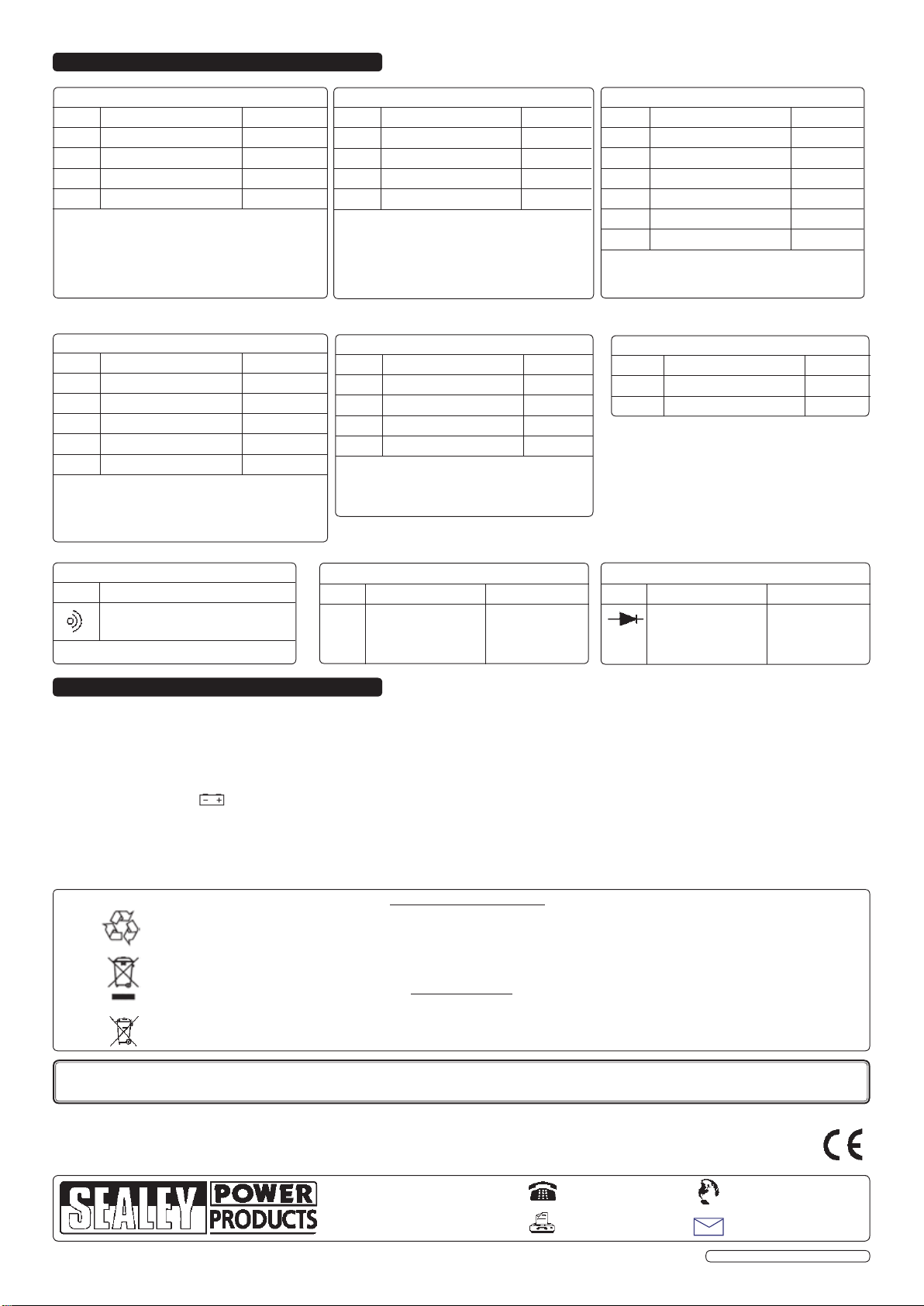
Sealey MM24 User manual

Quality tradesman's multimeter with easy to read 26mm LCD display. Features protective rubber boot, probe storage and integral stand.
Supplied with probe test leads.
1.1 PERSONAL PRECAUTIONS
When using this multimeter, please observe all normal safety rules concerning:
Protection against the dangers of electrical current.
Protection of the meter against misuse.
Full compliance with safety standards can only be guaranteed if used with the test leads supplied. If necessary, they must be replaced with
genuine Sealey leads with the same electrical ratings. Failure to do so will invalidate the warranty.
DO NOT use leads if damaged or if the wires are bared in any way.
1.2 GENERAL SAFETY INSTRUCTIONS
Familiarise yourself with the application and limitations of the multimeter as well as the potential hazards.
IF IN ANY DOUBT CONSULT A QUALIFIED ELECTRICIAN.
When the meter is connected to a circuit, do not touch unused meter terminals.
When the magnitude of the value to be measured is unknown, set the range selector to the highest value available.
Before commencing testing, follow instructions below and select the correct input sockets, function and range on the multimeter.
Before rotating the rotary switch to change functions, disconnect the test leads from the circuit under test.
Take care when working with voltages above 60V DC or 30V AC rms. Keep fingers behind the probe barriers whilst measuring.
DO NOT test voltages above 600V - the circuitry of the multimeter may be destroyed.
WARNING! NEVER connect the multimeter to a voltage source / live circuit when the rotary switch is set to any other function apart from
Voltage testing
WARNING! NEVER perform resistance, transistor, diode or continuity measurements on live circuits.
DO NOT use the multimeter in a potentually explosive atmosphere.
Ensure that the rear cover is in place and fastened before using the multimeter.
Before attempting to insert transistors for testing, ensure that test leads have been disconnected.
Components should not be connected to the transistor socket or capacitor socket when taking voltage measurements with the test leads.
If any abnormal readings are observed, the multimeter must be checked out by an authorised technician.
When not in use, store the multimeter carefully in a safe, dry, childproof location out of direct sunlight. Storage temperature range -10°C to 50°C.
INSTRUCTIONS FOR:
DIGITAL MULTIMETER
7 FUNCTION
MODEL No: MM24
Thank you for purchasing a Sealey product. Manufactured to a high standard this product will, if used according to these instructions and
properly maintained, give you years of trouble free performance.
1. SAFETY INSTRUCTIONS
IMPORTANT: PLEASE READ THESE INSTRUCTIONS CAREFULLY. NOTE THE SAFE OPERATIONAL REQUIREMENTS, WARNINGS & CAUTIONS. USE THE PRODUCT
CORRECTLY AND WITH CARE FOR THE PURPOSE FOR WHICH IT IS INTENDED. FAILURE TO DO SO MAY CAUSE DAMAGE AND/OR PERSONAL INJURY AND WILL
INVALIDATE THE WARRANTY. PLEASE KEEP THESE INSTRUCTIONS SAFE FOR FUTURE USE.
2. FEATURES
Features:
1. LCD Display
2. On/Off Button
3. Hold Button
4. Rotary Switch
5. 10A Socket
6. mA Socket
7. COM Socket
8. V/Ω Socket
9. Transistor Testing Socket
1
23
4
5
7
6
9
8
2
Function Measures Red Lead
Connection Input Limits
VDC Voltage V/Ω600V DC
V ~ AC Voltage V/Ω600V AC (sine)
ADC Current mA or 10A 10A DC
A ~ AC Current mA or 10A 10AAC
ΩResistance V/Ω20M Ω
BATT Battery Checker mA 9.0V
(200) Audible Continuity V/Ω-
(2k) Diode Verification Mode V/Ω-
hFE Transistor Verification Mode mA -
Original Language Version MM24 Issue No: 2 - 02/07/10

WARNING! Ensure that you read, understand and apply the safety and operational instructions before connecting the multimeter.
Only when you are sure that you understand the procedures, is it safe to proceed with testing.
Operating temperature range 0°C to 40°C.
If the battery sign appears on the display, it indicates that the battery power is low and must be replaced, see section 5.2.
NOTE: when the figure '1' is displayed, it indicates an over-range situation and a higher range needs to be selected.
Use the hold button to hold the displayed test reading, press button again to return to normal setting.
Switch on the multimeter each time immediately before measuring and turn it off when completed.
3.1. MEASURING VOLTAGE
3.1.1. Connect the black test lead to the COM input socket and the red test lead to the V/Ωinput socket.
3.1.2. Set the rotary switch to the required V (DC) or V ~ (AC) range and connect test leads across the device or circuit under
measurement.
3.1.3. Turn on the power to the device or circuit, the voltage measured will be displayed. The polarity of the red test lead connection will be
indicated when measuring DC voltages.
NOTE: At low voltage settings, the display may show fluctuating readings when the probes are not connected, due to the sensitivity of
the multimeter. If a circuit of over 600V is accidently measured, the buzzer will sound as a warning.
3.2. MEASURING CURRENT
3.2.1. Connect the black test lead to the COM input socket and the red test lead to either the mA input socket for measuring a maximum of
200mA or the 10A input socket for measuring a maximum of 10A.
3.2.2. Set the rotary switch to the required A (DC) or A ~ (AC) range (note: the 10A setting in brackets) and connect test leads in series
with the circuit under measurement, open the circuit and the current measured will be displayed.
NOTE: The polarity of the red lead connection will be indicated when measuring dc current.
3.3. MEASURING RESISTANCE
3.3.1. Connect the black test lead to the COM input socket and the red test lead to the V/Ωinput socket (the polarity of the red lead is ‘+’).
3.3.2. When checking in-circuit resistance, ensure that the circuit under test has all power removed and all capacitors have been fully
discharged.
3.3.3. Set the rotary switch to the required Ω range and connect the test leads across the resistance under measurement. The resistance
measured will be displayed.
3.3.4. When measuring resistance over 1MΩ, the meter may take a few seconds to get a stable reading. This is normal for high resistance
measurements.
3.4. DIODE TESTING
3.4.1. Connect the black test lead to the COM input socket and the red test lead to the V/Ωinput socket (the polarity of the red lead is ‘+’).
3.4.2. Set the rotary switch to the position and connect the red probe to the anode and the black probe to the cathode of the diode
under test. The display will show the forward voltage drop of the diode. If the probes are reverse connected, a figure ‘1’ will be displayed.
3.5. TRANSISTOR TESTING
3.5.1. Determine whether the transistor to be tested in NPN or PNP type and locate the Emitter, Base and Collector leads. Insert leads of the
transistor into the correct sockets in the external transistor testing socket. Connect the black lead to the COM input socket and the red
lead to the V/Ωinput socket. Insert the probes correctly into the external tester. Set the rotary switch to the hFE position.
3.5.2. The display will show the approximate hFE value at test conditions of base current 10µA and Vce 2.8V.
3.6. AUDIBLE CONTINUITY TEST
3.6.1. Connect the black test lead to the COM input socket and the red test lead to the V/Ωinput socket (the polarity of the red lead is ‘+’).
3.6.2. Set the rotary switch to the position and connect the test leads across the two points of the circuit under test. If continuity exists (i.e.
resistance less than about 30Ω) the built-in buzzer will sound.
3.7. BATTERY TESTING
3.7.1. Connect the black test lead to the COM input socket and the red test lead to the mA input socket.
3.7.2. Set the rotary switch to the appropriate battery voltage position (1.5V or 9V). Touch the probes onto the terminals of the battery to be
tested, the display will show the voltage of the battery (a negative voltage will be shown if the probes are reversed).
3. OPERATION
DC Voltage
Range
AC Voltage
Range
DC Current
Range
Battery Test
Transistor
Test
Continuity
Test
Diode Test
Resistance
Range
AC Current
Range
Original Language Version MM24 Issue No: 2 - 02/07/10

5. MAINTENANCE
4. SPECIFICATION
WARNING! Before attempting to open the case, ensure that the test leads have been disconnected from the multimeter and that it is
switched off to avoid electric shock hazard.
5.1. Changing a fuse.The fuses are located on the back of the circuit board. To gain access to the fuses, remove the protective rubber boot and
the two screws from the rear of the multimeter. Lift off the rear cover, replace the appropriate fuse and re-assemble in reverse order.
WARNING! ALWAYS replace a fuse with one of the correct rating.
Fuse 1: 500mA/250V
Fuse 2: 10A/250V
5.2. If the battery sign appears on the LCD display, it indicates that the battery must be replaced. Repeat the steps detailed in section
5.1 to remove the rear cover, replace the battery (9V PP3) and re-assemble in reverse order.
5.3. Clean the multimeter's casing using a slightly dampened cloth and mild detergent - do not use any abrasives or solvents. Clean the inside
of each terminal using a swab soaked in isopropyl alcohol, use a new swab to apply a light coat of machine oil to each terminal.
5.4.If the multimeter is to be stored for a long period of time, remove the battery first to avoid any damage.
DC VOLTAGE
Range Accuracy Resolution
200mV ±0.8% of reading ±4 digits 100µV
2V ±0.8% of reading ±4 digits 1mV
20V ±0.8% of reading ±4 digits 10mV
200V ±0.8% of reading ±4 digits 100mV
600V ±1.2% of reading ±4 digits 1V
Input impedance: 10MΩfor all ranges. Overload
Protection: 600V dc or peak ac on all ranges.
Overload Protection:200V rms ac for 200mV range and
600V dc or ac for other ranges.
AC VOLTAGE
Range Accuracy Resolution
2V ±0.8% of reading ±5 digits 1mV
20V ±0.8% of reading ±5 digits 10mV
200V ±0.8% of reading ±5 digits 100mV
600V ±1.2% of reading ±4 digits 1V
Input impedance: 10MΩfor all ranges.
Frequency Range: 40Hz to 1kHz
Overload Protection: 220V rms ac for 200mV range and
600V dc or ac for other ranges.
Indication: Average (rms of sine wave).
DC CURRENT
Range Accuracy Resolution
2mA ±0.8% of reading ±4 digits 1µA
20mA ±0.8% of reading ±4 digits 10µA
200mA ±1.2% of reading ±5 digits 100µA
10A ±2.0% of reading ±5 digits 10mA
Overload protection: Fuse 1: 500mA/250V
Maximum Input Current: Fuse 2: 10A/250V (10A
up to 15 seconds).
Measuring Voltage Drop: 200mV.
AUDIBLE CONTINUITY TEST
Range Description
Buzzer sounds if
resistance is less than 30 Ohms
Open Circuit Voltageapproximately 2.8V
BATTERY TEST
Range Accuracy Current
1.5V ±0.8% of reading ±2 digits 60mA
9.0V ±0.8% of reading ±2 digits 12mA
TRANSISTOR hFE TEST (External test socket)
Range Description Test Condition
hFE Displays approximate
hFE value (1-1000) of
transistor.
Base current
approximately 10µA.
VCE approximately
2.8V.
AC CURRENT
Range Accuracy Resolution
2mA ±1.2% of reading ±3 digits 1µA
20mA ±2.0% of reading ±3 digits 10µA
200mA ±2.0% of reading ±3 digits 100µA
10A ±3.0% of reading ±7 digits 10mA
Overload protection: Fuse 1: 500mA/250V
Indication: Average (rms of sine wave).
Maximum Input Current: Fuse 2: 10A/250V (10A
up to 15 seconds).
Measuring Voltage Drop: 200mV.
Frequency Range: 40Hz to 1kHz.
RESISTANCE
Range Accuracy Resolution
200Ω±1.0% of reading ±8 digits 0.1Ω
2kΩ±1.2% of reading ±8 digits 1Ω
20kΩ±1.2% of reading ±8 digits 10Ω
200kΩ±1.2% of reading ±8 digits 100Ω
2MΩ±1.2% of reading ±8 digits 1kΩ
20MΩ±1.2% of reading ±8 digits 10kΩ
Maximum open circuit voltage less than 750mV.
Overload protection: 220V dc/ac rms on all ranges.
Environmental Protection.
Recycle unwanted materials instead of disposing of them as waste. All tools, accessories and packaging should be sorted,
taken to a recycle centre and disposed of in a manner which is compatible with the environment.
When the product is no longer required, it must be disposed of in an environmentally protective way.
Battery Removal.
See Section 5.2.1. Remove and dispose of according to local authority guidelines.2.
NOTE: It is our policy to continually improve products and as such we reserve the right to alter data, specifications and component parts without prior notice.
IMPORTANT: No liability is accepted for incorrect use of this product.
WARRANTY: Guarantee is 12 months from purchase date, proof of which will be required for any claim.
INFORMATION: For a copy of our latest catalogue and promotions call us on 01284 757525 and leave your full name and address, including postcode.
Sole UK Distributor, Sealey Group,
Kempson Way, Suffolk Business Park,
Bury St. Edmunds, Suffolk,
IP32 7AR
Original Language Version
01284 757500
01284 703534
sales@sealey.co.uk
www.sealey.co.uk
Web
email
MM24 Issue No: 2 - 02/07/10
DIODE TEST
Range Description Test Condition
(2k)
Displays approximate
forward Voltage of
Diode
Forward DC current
approximately 1mA.
Reversed DC voltage
approximately 2.8V
Parts support is available for this product. To obtain a parts listing and/or diagram,
please log on to www.sealey.co.uk, email sales@sealey.co.uk or phone 01284 757500.
Table of contents
Other Sealey Multimeter manuals

Sealey
Sealey TA311 User manual

Sealey
Sealey MM18 User manual

Sealey
Sealey TM102 User manual

Sealey
Sealey MM104.V2 User manual

Sealey
Sealey MM402 User manual

Sealey
Sealey MM102 User manual

Sealey
Sealey Professional MM20 User manual

Sealey
Sealey TM101 User manual

Sealey
Sealey Auto Service Series User manual

Sealey
Sealey MM20.V2 User manual

Sealey
Sealey MM302.V2 User manual

Sealey
Sealey TM105 User manual

Sealey
Sealey TM104 User manual

Sealey
Sealey MM18 User manual

Sealey
Sealey Professional MM19.V2 User manual

Sealey
Sealey TA330 User manual

Sealey
Sealey TA202 User manual

Sealey
Sealey MM104 User manual

Sealey
Sealey TM100 User manual

Sealey
Sealey TM103 User manual