Sealey SA35 User manual

Thank you for purchasing a Sealey Product. Manufactured to a high standard this product will, if used according to these instructions
and properly maintained, give you years of trouble free performance.
IMPORTANT:PLEASE READ THESE INSTRUCTIONS CAREFULLY. NOTE THE SAFE OPERATIONAL REQUIREMENTS,
WARNINGS AND CAUTIONS. USE THIS PRODUCT CORRECTLY AND WITH CARE FOR THE PURPOSE FOR WHICH
IT IS INTENDED. FAILURE TO DO SO MAY CAUSE DAMAGE AND/OR PERSONAL INJURY AND WILL INVALIDATE
THE WARRANTY. PLEASE KEEP INSTRUCTIONS SAFE FOR FUTURE USE.
1. SAFETY INSTRUCTIONS
pWARNING! Ensure Health & Safety, local authority, and general workshop practice regulations are adhered to
when using this equipment.
pWARNING! Disconnect from air supply before changing accessories or servicing.
3Maintain the sander in good condition (use an authorised service agent).
3Replace or repair damaged parts. Use genuine parts only. Unauthorised parts may be dangerous and
will invalidate the warranty.
3Use in suitable clean and tidy working area, free from unrelated materials and ensure there is adequate lighting.
3Before each use check abrasive belt for condition. If worn or damaged replace immediately.
3Use only the correct size and type of sanding belt with this sander.
3Ensure there are no flammable or combustible materials near the work area.
pWARNING! Always wear approved eye or face and hand protection when operating the sander.
3Use face, dust, or respiratory protection in accordance with COSHH regulations.
3Depending on the task, sander noise level may exceed 85dB, in which case wear safety ear defenders.
3Remove ill fitting clothing. Remove ties, watches, rings, other loose jewellery and contain and/or tie back long hair.
3Wear appropriate protective clothing and keep hands and body clear of working parts.
3Maintain correct balance and footing. Ensure the floor is not slippery and wear non-slip shoes.
3Keep children and unauthorised persons away from the work area.
3Check moving parts alignment on a regular basis.
3Ensure workpiece is secure before operating the sander. Never hold a workpiece by hand.
3Check the workpiece to ensure there are no protruding screws, bolts, nuts, nails, rivets, etc.
3Avoid unintentional starting.
pWARNING! Ensure correct air pressure is maintained and not exceeded. Recommended pressure 70-90psi.
3Keep air hose away from heat, oil and sharp edges. Check air hose for wear before each use and ensure
that all connections are secure.
3Prolonged exposure to vibration from this sander poses a health risk. It is the owners responsibility to correctly
assess the potential hazard and issue guidelines for safe periods of use and offer suitable protective equipment.
7DO NOT use the sander for a task it is not designed to perform.
7DO NOT operate sander if any parts are damaged or missing as this may cause failure and/or personal injury.
pWARNING! DO NOT sand any materials containing asbestos.
7DO NOT carry the sander by the hose, or yank the hose from the air supply.
7DO NOT force, or apply heavy pressure to, the sander, let the sander do the work.
7DO NOT switch the sander on whilst the belt is in contact with the workpiece.
7DO NOT operate sander when you are tired or under the influence of alcohol, drugs or intoxicating medication.
7DO NOT use sander where there are flammable liquids, solids or gases such as paint solvents and including
waste wiping or cleaning rags etc.
7DO NOT carry the sander with your finger on the power lever.
7DO NOT direct air from the air hose at yourself or others.
3When not in use disconnect from air supply and store in a safe, dry, childproof location.
SA35 - 0016 - (1) - 290301
INSTRUCTIONS FOR
AIR OPERATED 10mm BELT
SANDER
Model: SA35
01284 757500 E-mail: sales@sealey.co.uk
01284 703534
NOTE: It is our policy to continually improve products and as such we reserve the right to alter data, specifications and component
parts without prior notice. IMPORTANT: No liability is accepted for incorrect use of this equipment. WARRANTY: Guarantee is 12
months from purchase date, proof of which will be required for any claim. INFORMATION: For a copy of our latest catalogue and
promotions call us on 01284 757525 and leave your full name and address, including postcode.
Sole UK Distributor, Sealey Group, Bury St. Edmunds, Suffolk.
Item Part No. Description
1SA35/B60G Belt, 60G (pack of 5)
SA35/B80G Belt, 80G (pack of 5)
SA35/B100G Belt, 100G (pack of 5)
SA35/B120G Belt, 120G (pack of 5)
2 Idle Pulley Sub Assy
3 Washer
4 Idle Pulley Shaft
5 Bracket
6 Tension Bar
7 Hex Set Screw
8 Screw
9 Spring
10 Spring Pins
11 Spring
12 SA35/93/12 Shoe
13 SA35/93/13 Screw
14 SA35/93/14 Guard Sub Assembly
15 SA35/93/15 Hex Bolt
16 SA35/93/16 Hex Nut
17 SA35/93/17 Drive Pulley
18 SA35/93/18 Housing
19 B/628ZZ Bearing
20 SA35/93/20 End Plate
Item Part No. Description
21 SA35/93/21 Spacer
22 SA35/93/22 Sunk Key
23 SA35/93/23 Cap
24 B/607ZZ Ball Bearing
25 SA35/93/25 End Plate
26 SA35/93/26 Cylinder
27 SA35/93/27 Blade Assy
28 SA35/93/28 Rotor
29 SA35/93/29 Throttle Lever
30 SA35/93/30 Lever Pin
31 SA35/93/31 Valve Body
32 SA35/93/32 O-Ring
33 SA35/93/33 O-Ring
34 SA35/93/34 O-Ring
35 SA35/93/35 Valve Stem
36 SA35/93/36 O-Ring
37 SA35/93/37 Valve Spring
38 SA35/93/38 Deflector
39 SA35/93/39 Air Inlet
40 Tension Bar
41 Spring
42 Lever Pin
43 Lever Pin
SA35/93/06-TBA Tension Bar Assy
Items marked are components of Tension Bar Assembly.
Items 14 &15 are also available separately.

4.1. Unpack the product and check contents against
the parts listed below. If there is anything
damaged or missing contact your supplier
immediately.
Contents: a) SA35 Belt Sander.
b) 3 x Sanding Belt c) 2 x Hex. Key
pWARNING! Ensure that you have read and understood
the safety instructions in Section 1.
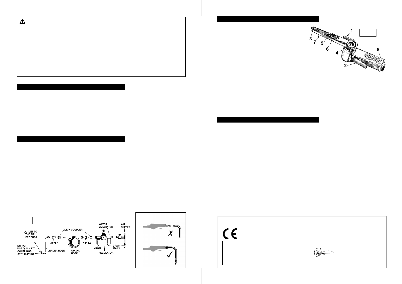
4.2. Loosening clamp bolt (fig.3.1. on the top of sander) allows the
angle between the grip and the belt to be altered to suit the job in hand.
After adjustment retighten the clamp bolt.
4.3. Once connected to the air supply the sander is started by squeezing the trigger (2).
4.4. To remove and replace the sanding belt push the idle pulley (3) towards the drive pulley (4) against
spring pressure. The pulley bracket (5) will retract and lock allowing removal/fitting of the belt. When the
new belt is in position release the pulley bracket by pushing in and holding the idle pulley, then press and
hold the tension bar (6) whilst releasing the pressure on the idle pulley.
4.5. The tracking of the belt can be altered by adjusted cross head screw (7).
2. INTRODUCTION & SPECIFICATION
3.1. Air Supply
3.1.1. Ensure the sander air valve (or throttle) is in the "off" position before connecting to the air supply.
3.1.2. You will require an air pressure between 70-90psi, and an air flow of 12cfm.
3.1.3. pWARNING! Ensure the air supply is clean and does not exceed 90 psi.
Too high an air pressure and unclean air will shorten the product life due to excessive wear, and may be
dangerous causing damage and/or personal injury.
3.1.4. Drain the air tank daily. Water in the air line will damage the sander and will invalidate your warranty.
3.1.5. Clean compressor air inlet filter weekly. Recommended hook-up procedure is shown in fig.1.
3.1.6. Line pressure should be increased to compensate for unusually long air hoses (over 8 metres).
The minimum hose size should be 1/4 I.D. and fittings must have the same inside dimensions.
3.1.7. Keep hoses away from heat, oil and sharp edges. Check hoses for wear, and make certain that all
connections are secure.
3.2. Couplings.
Vibration may cause failure if a quick change coupling is connected directly to the air sander. To overcome this,
connect a leader hose to the sander. A quick change coupling may then be used to connect the leader hose to the
air line recoil hose. See figs.1 & 2.
pWARNING! Disconnect sander from air supply before changing accessories, servicing or performing
maintenance. Replace or repair damaged parts. Use genuine parts only. Unauthorised parts may be
dangerous and will invalidate the warranty.
5.1. If the air supply system does not have an oiler lubricate the sander daily with a few drops of a good
grade air tool oil, such as Sealey ATO/500 or ATO/1000, dripped into the air inlet (fig.3.8) before use.
5.2. Clean the sander after use and change belt when required.
5.3. Loss of power or erratic action may be due to the following:
a) Excessive drain on the air supply. Moisture or restriction in the air line. Incorrect size or type of hose
connectors. To remedy, check the air supply and follow instructions in Section 3.
b) Grit or gum deposits in the sander may also reduce performance. If your model has an air filter
(located in the area of the air inlet), remove the filter and clean it. Flush the sander out with gum
solvent oil or an equal mixture of SAE No. 10 oil and kerosene. Allow to dry before use.
If you continue to experience problems, contact your local Sealey service agent.
5.4. For a full service contact your local Sealey service agent.
5.5. When not in use, disconnect from air supply, clean and store in a safe, dry, childproof location.
3. PREPARING FOR USE
4. OPERATING INSTRUCTIONS
5. MAINTENANCE
1.2. LEAD PAINT WARNING!
Paint once contained lead as a traditional ingredient. The dust from the removal of such paint is toxic if
ingested/inhaled and must, therefore, be avoided. The following actions must be taken before
using the sander on a surface that you suspect may contain lead paint.
1. User must determine potential hazard relating to age of paint to be removed.
(Modern paints do not have lead content).
2. DANGER! Keep all persons and pets away from the work area. The following persons are
particularly vulnerable to the effects of lead paint dust: Expectant women, babies and children.
3. We recommend personal protection by using the following safety items:
a) Paint Spray Respirator (Sealey ref. SSP16EN)
b) PE Coated Hooded Coverall (Sealey ref. SSP266). c) Latex Gloves (Sealey ref. SSP24).
4. Take adequate measures to contain the paint dust, flakes and scrapings.
5. Continue to wear safety equipment as in (3) above and thoroughly clean all areas when task is
complete. Ensure paint waste is disposed of in sealed bags or containers.
fig. 1
We, the sole importer into the UK, declare that the product listed here is in conformity with the
following standards and directives. The construction file for this product is held by the
Manufacturer and may be inspected, by a national authority, upon request to Jack Sealey Ltd.
For Jack Sealey Ltd. Sole distributor in the UK
of Sealey Power Products.
Air Operated 10mm Belt Sander
Model SA35
98/37/EC Machinery Directive
93/68/EEC Marking Directive
30th March 2001
Declaration of Conformity
Signed by Mark Sweetman
SA35 - 0016 - (1) - 290301
fig. 2
Specification
Belt . . . . . . . . . . . . . .10 x 320mm
Air Pressure . . . . . . . . . . . . .90psi
Air Consumption . . . . . . . . .12cfm
Air inlet . . . . . . . . . . . . . . .1/4BSP
The SA35 Belt Sander features an articulated sanding arm, belt tracking control, heavy-duty nose roller and one-
handed trigger operation. Suitable for sanding areas with limited access.
Weight . . . . . . . . . . . . . . . . .0.8kg
Airborne Noise . . . . . . .87.8dB (A)
86.5dB (C)
Vibration level . . . . . . . . .<2.5m/s2
fig. 3
Other Sealey Sander manuals

Sealey
Sealey SA32 User manual

Sealey
Sealey MS800PS User manual

Sealey
Sealey OP750 User manual

Sealey
Sealey Quality MACHINERY SM1301 User manual

Sealey
Sealey SM31.V3 User manual

Sealey
Sealey SA1003 User manual

Sealey
Sealey SM31.V3 User manual

Sealey
Sealey ER230P.V2 User manual

Sealey
Sealey SA18/S.V2 User manual

Sealey
Sealey SA800.V4 User manual

Sealey
Sealey GSA07 User manual

Sealey
Sealey Quality MACHINERY SM15.V2 User manual

Sealey
Sealey SA7/SAS User manual

Sealey
Sealey ER1700P.V2 User manual

Sealey
Sealey OS400 User manual

Sealey
Sealey CP2518L User manual

Sealey
Sealey SM1214 User manual

Sealey
Sealey SA32.V2 User manual

Sealey
Sealey SA720.V2 User manual

Sealey
Sealey CP108VCPBO User manual