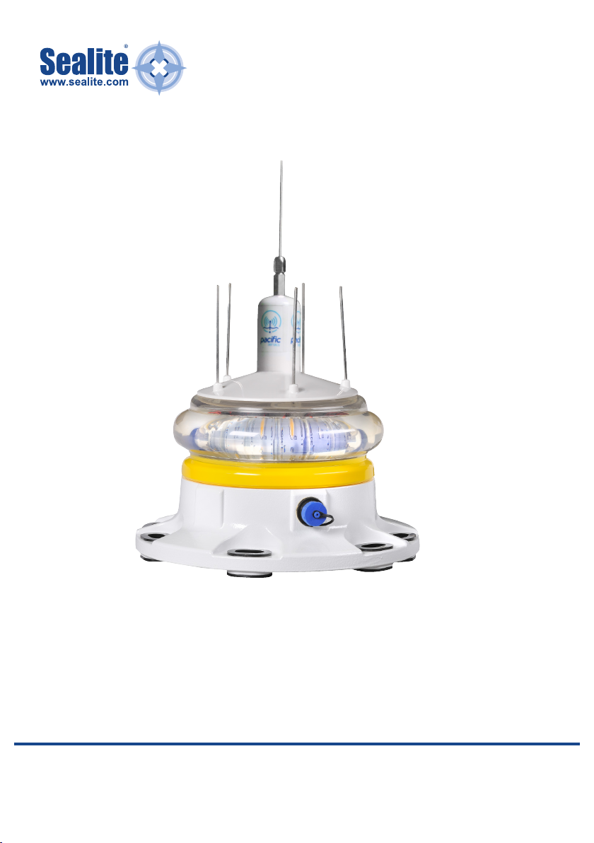
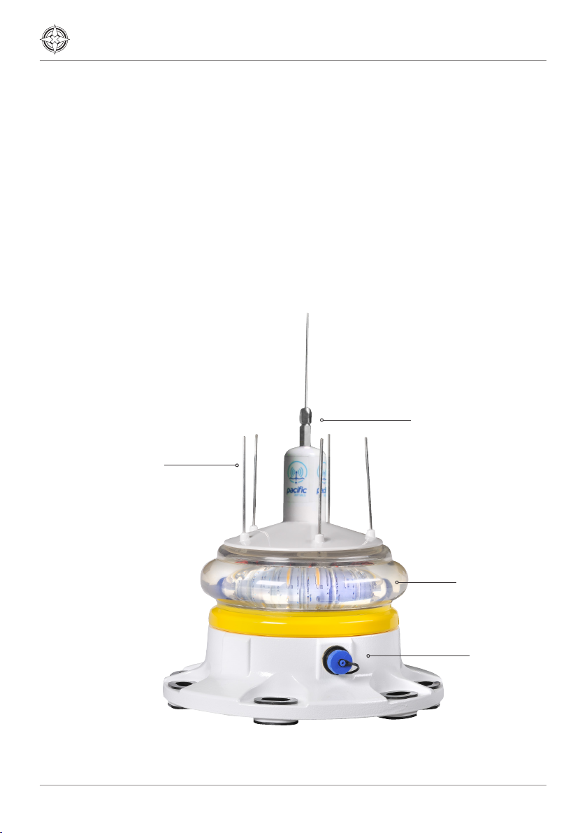
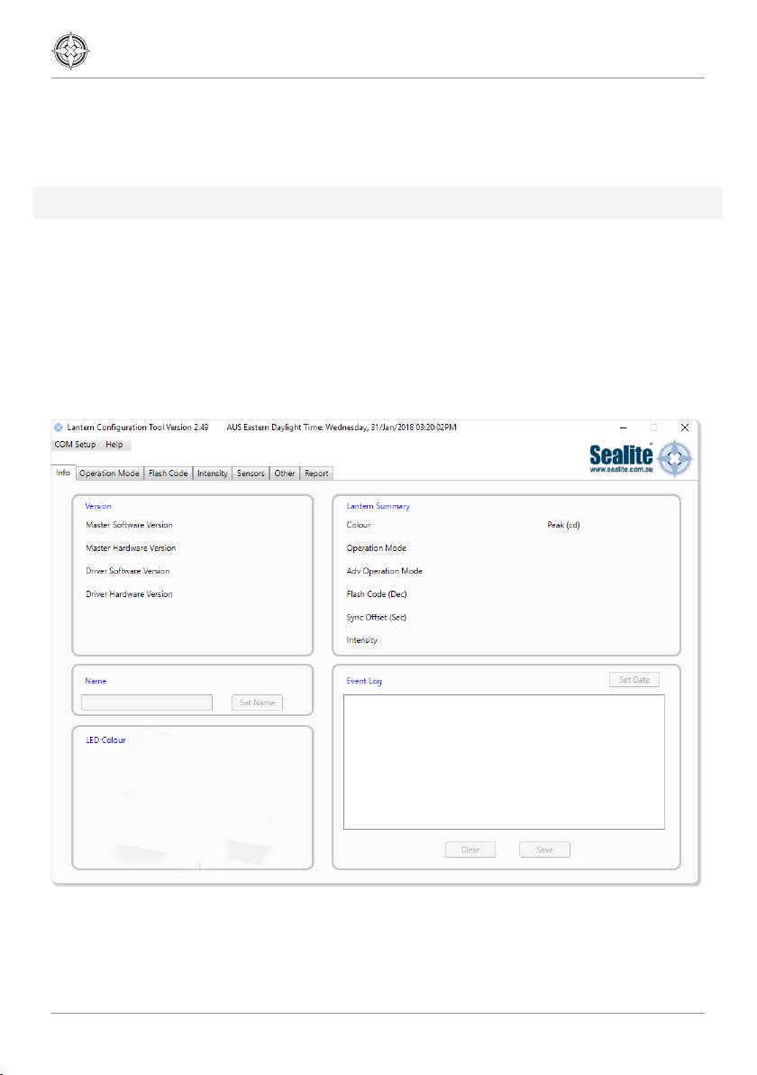
Sealite SL-155 Series Supplement

SL-155 Series
SL-155-5D/10D Models
with integrated AIS Marine Lanterns
V5.3
INSTALLATION & SERVICE MANUAL

2
Introduction 4
Operating Principle 4
Technology 5
Specifications 6
Product Components 9
Programming the Lantern 10
PC Configuration Tool.....................................................................................................10
Info Tab.........................................................................................................................14
Operation Mode Tab .....................................................................................................15
Flash Code ................................................................................................................... 17
Intensity .......................................................................................................................18
Sensors ........................................................................................................................19
AIS Report ....................................................................................................................21
IR Programmer 22
Sealite IR Programmer / Universal Remote Compatibility ................................................ 22
IR Programmer Functions ............................................................................................ 23
SL-155 Series Lantern 28
Power Consumption ..................................................................................................... 28
Thermal Management .................................................................................................29
Lantern Data ...............................................................................................................30
Power Supply Design Considerations 33
Lantern Testing 34
Lantern Installation 35
GPS Synchronisation 42
Lantern Testing 43
Lantern Installation 43
Table of Contents

SL-155-5D/10D Models (integrated AIS)
6-13NM Marine Lanterns
Latest products and information available at www.sealite.com 3
Optional GPS Synchronisation 49
AIS System 43
Type 1 AIS AtoN............................................................................................................43
Type 3 AIS AtoN ...........................................................................................................43
GNSS systems .............................................................................................................43
Supported AIS Messages 44
Installation....................................................................................................................45
Transceiver configuration.............................................................................................. 48
FATDMA Schedule configuration....................................................................................52
RATDMA Schedule configuration ................................................................................... 54
Virtual AtoN configuration .............................................................................................56
Status input configuration tab........................................................................................ 57
Alert messages ............................................................................................................58
Off position alert...........................................................................................................60
SART Relay Mode.........................................................................................................60
Transceiver diagnostics 61
GNSS tab ......................................................................................................................61
Serial Data tab...............................................................................................................61
Diagnostics tab.............................................................................................................62
Report generation......................................................................................................... 62
Reported messages 63
Active alarms ...............................................................................................................64
Maintenance & Servicing 65
Trouble Shooting 66
Appendix – Flash Codes 67
Sealite LED Light Warranty 74
Notes 75

4
Introduction
Congratulations! By choosing to purchase a Sealite lantern you
have become the owner of one of the most advanced LED marine
lanterns in the world.
Sealite Pty Ltd has been manufacturing lanterns for over 25 years, and particular care has
been taken to ensure your lantern gives years of service.
As a commitment to producing the highest quality products for our customers, Sealite has
been independently certified as complying with the requirements of ISO9001:2015 quality
management system. Sealite lanterns comply with requirements of the US Coast Guard in
33 CFR part 66 for Private Aids To Navigation.
By taking a few moments to browse through this booklet, you will become familiar with the
versatility of your lantern, and be able to maximise its operating function.
Operating Principle
A microprocessor drives an array of ultra-bright LED’s through a
DC/DC converter, which enables the LED’s to operate within the
manufacturer’s specifications.
On darkness, the microprocessor will initiate a program check and after approximately 1
minute begin flashing to the set Flash Character.
The flasher unit has a low current requirement to optimise its use with external battery
power supply systems.

SL-155-5D/10D Models (integrated AIS)
6-13NM Marine Lanterns
Latest products and information available at www.sealite.com 5
Technology
Sealite is the world’s fastest growing manufacturer of marine aids
to navigation. We employ leading mechanical, optical, hardware
& software engineers to create innovative products to service the
needs of our customers worldwide, and offer the widest range of
solar-powered LED lanterns in the marketplace.
Electronics
Sealite employs leading in-house electronic engineers in the design and development of
software and related circuitry. All individual electronic components are sourced directly by
Sealite procurement staff ensuring that only the highest quality components are used in
our products.
LED Technology
All marine lanterns use the latest advancements in LED (Light Emitting Diode) technology
as a light source. The major advantage of LED’s over traditional light sources is well
established in that they typically have an operational life in excess of 100,000 hours,
resulting in substantial savings to maintenance and servicing costs.
Precision Construction
Commitment to investing in the design and construction of injection-moulded parts
including optic lenses, light bases and a range of other components ensures that all Sealite
products are of a consistent & superior quality.
Optical Performance
Sealite manufactures a range of marine LED lenses moulded from multi-cavity dies. The
company has superior in-house lens manufacturing capabilities to support outstanding
optical performance.
Award-winning, Patented Technology
Several United States and Australian patent registrations are held on Sealite’s range of
innovative designs, with other regional patents pending in Canada, United Kingdom and
Europe.

6
Specifications
SL-155 Series 6-13NM Marine Lanterns SL-155-5D/10D Models
The SL-155 Complete Lantern Assembly provides a complete solution for visual
navigation requirements and is available with remote monitoring and control capabilities
allowing the performance of the units to be monitored from remote sites. System status
includes battery condition, flash characters, operational configuration, and lantern/buoy
position.
Integrated AIS
VHF Antenna
Integrated bird
deterrent
UV-stabilised
acrylic lens
Painted
aluminium base

SL-155-5D/10D Models (integrated AIS)
6-13NM Marine Lanterns
Latest products and information available at www.sealite.com 7
Technical Drawings
PCD 200
30°
16 x 15 Slots
6 Places
230
98
222
1104
239

8
Specifications • * 5oand 10oModels
Light Characteristics
Light Source High efficiency LEDs
Available Colours Red, Green, White, Yellow
Maximum Luminous Intensity (cd)† 5 degree model: Red - 2,765 Green - 2,796 White - 4,611 Yellow - 2,778
10 degree model: Red - 2,368 Green - 2,213 White - 3,910 Yellow - 2,041
Visible Range (NM) AT @ 0.74: 6–13
AT @ 0.85: 7.8–19.2
Horizontal Output (degrees) 0o- 360o
Vertical Divergence (degrees) 5oor 10o
Available Flash Characteristics Up to 310 including 256 IALA recommended, & 1 custom
Intensity Adjustments User adjustable
LED Life Expectancy (hours) >100,000
Electrical Characteristics
Average Power (W) Variable up to 18
Circuit Protection Polarity protected
Nominal Voltage (VDC) 12–24
Temperature Range -40 to 80°C
Physical Characteristics
Body Material Marine grade two-part epoxy coating
Lens Material UV-stabilised acrylic
Lens Diameter (mm/inches) 171 / 6¾
Lens Design Multiple LED optic
Mounting 3 & 4 hole 200mm bolt pattern
Height (mm/inches) 217 / 8½
Width (mm/inches) 230 / 9
Mass (kg/lbs) 5 / 11
Product Life Expectancy Up to 12 years
Environmental Standards
Shock MIL-STD-202G Test Condition H, Method 213B 30G vertical and 35G horizontal shock
Vibration MIL-STD-202G, Test Condition B, Method 204D 5G in all axes
Immersion MIL-STD-202G, Method 104A
Ice Loading Rated to withstand 22kg/m2
Humidity 0 – 100%, condensing
Waterproof IP68
Certifications
CE & Electrical FCC Part 15 Rules & ICES-003.
EN61000-6-1: 2007 (IEC61000-6-1:2005) Part 6-1 Immunity. EN61000-6-3: 2007
(IEC61000-6-3: 2006) Electromagnetic compatibility (EMC) - Part 6-3 Emission.
IEC61000-4-2: 2008 Ed 2 Part 4-2 Electrostatic discharge immunity test Level 4.
IEC61000-4-3: 2010 Ed 3.2 Part 4-3. Radiated, radio-frequency, electromagnetic field
immunity.
IEC61000-4-6: 2008 Ed3. , Electromagnetic compatibility
(EMC) - Part 4-6 Immunity.
IALA Signal colours compliant to IALA E-200-1
Quality Assurance ISO9001:2015
Intellectual Property
Trademarks SEALITE®is a registered trademark of Sealite Pty Ltd
Warranty * 3 years
Options Available • GPS Synchronisation
• AIS Type 1 or Type 3
• GSM Monitoring & Control System
• RS232/422/485 Communication Port
• General purpose input & output
• Variety of solar/battery configurations
• Serial programming cable
• Hard-wire Synchronisation
• Specifications subject to change or variation without notice * Subject to standard terms and conditions † Intensity setting subject to solar availability

SL-155-5D/10D Models (integrated AIS)
6-13NM Marine Lanterns
Latest products and information available at www.sealite.com 9
Product Components
The following components come standard with each lantern:-
• SL-155 lantern
• IR Programmer
• Installation & service manual
• AIS programming Cable
• Lantern programming Cable
• USB Stick containing Lantern and AIS Configuration PC Application
These components are securely packaged within foam in a carton, and shipped to you.
PLEASE NOTE: The programming cable provided is suitable for use with PC’s.
Please check that ALL of these components are included with your order, and contact your
Sealite representative as soon as possible if anything is missing.

10
Programming the Lantern
PC Configuration Tool
The lantern is pre-programmed to the customer’s specific requirements for convenience
(eg. Flash, intensity setting etc).
The SL-155 Series are extremely intelligent lanterns with a number of features which can
be programmed directly via a user-friendly computer program (as supplied on USB drive
with every lantern).
To change/update the settings of your lantern, please read the following instructions.
Image 1. Sealite PC Configuration Tool

SL-155-5D/10D Models (integrated AIS)
6-13NM Marine Lanterns
Latest products and information available at www.sealite.com 11
1. Run the Programming Software
The programming software may be run directly from the USB drive provided, or you may
copy the software to your computer hard-drive for future use.
Running the Programming Software from the USB Drive
• Connect the USB drive to your computer
• Navigate to the USB drive folder & double-click the file called “LanternConfig.exe”. A new
window will appear displaying the PC Configuration Tool.
Saving the Programming Software to Computer Hard-Drive
• Connect the USB drive to your computer
• Navigate to the USB drive folder
• Copy the file called “LanternConfig.exe” and the “.dll” files
• Navigate to the hard-drive location where you would like to save this program, and then
right-mouse-click and select “paste”. A copy of the programming software will now be
saved to your computer hard-drive (to add the programmer to your computer desktop
for ease of future access, right-mouse-click and select “Send to desktop”)
• Double-click the file called “LanternConfig.exe”. A new window will appear displaying the
PC Configuration Tool
PLEASE NOTE: other documents have been saved on the USB drive for your information &
convenience including the latest product specifications sheet and an electronic version of
the installation and service manual. You may wish to view these documents to read more
about the innovative features and benefits of the SL-155 Series of lanterns.
IMPORTANT: the Sealite PC Configuration Tool is designed for Windows Platforms
only.
2. Connect the SL-155 Series Lantern to a Power Source & the Computer
Now that the programming software has been run, you will need to connect the lantern to
your computer & power supply so that it can receive programming commands.
Once connection is made, the software automatically determines the colour and
preprogrammed settings of the lantern.
Connecting the Lantern to a Power Source
Option 1: Battery
• Connect the blue negative wire of the lantern to the battery negative terminal
• Connect the brown positive wire of the lantern to the battery positive terminal
Option 2: 12V Power Supply
• Connect the blue negative wire of the lantern to the power supply negative terminal
• Connect the brown positive wire of the lantern to the power supply positive terminal
CAUTION: to avoid personal injury do not position the lantern at eye level.

12
Connecting the Lantern to the Computer
• Plug the Bulgin connector end of the programming cable into the lantern PC
Programming Port, and either the serial port end of the cable into your computer serial/
communication port or use the serial port to USB connector if working to a laptop.
3. Establish the Programmer-to-Lantern Computer Connection (COM Port)
Now that the lantern is connected to the computer and the Sealite PC Configuration
software has been run, the user must create
the programmer-to-lantern connection.
The COM Port is the hardware port which the computer accesses when communicating
with the lantern.
• Click the “COM Setup” at the top left
of the PC Configuration Tool to open the
“Serial Port” dialogue box
• In the “Serial Port” dialogue box select
the appropriate COM Port from the
drop down field for “Port Name”
• Check the “Open Port” check box to open
the port
• Click the “OK” button to initiate the
connection
The Sealite PC Configuration Tool will then
attempt to connect/interrogate the lantern.
Image 2. Serial Port dialogue box

SL-155-5D/10D Models (integrated AIS)
6-13NM Marine Lanterns
Latest products and information available at www.sealite.com 13
Image 3. Sealite Configuration Tool “Info” tab - showing COM Port connection established, Version &
Lantern Summary information.
Correct Connection Established
If the connection is established data about the lantern configuration will appear on the
“Info” tab under the headings “Version” & “Lantern Summary” (eg. Lantern Colour, Flash
Code, Intensity etc).
Connection NOT Established
If the connection is not available, the Sealite PC Configuration Tool will not display any
lantern specific information under the headings “Version” & “Lantern Summary”. If this
error occurs, please check the following:
• Reconnect the lantern to the computer
• Check that the lantern power supply has sufficient charge (eg. Battery is charged), and
then reconnect it to the lantern
• Re-run the Sealite PC Configuration Tool and follow the information in step 3. The
connection should now become established.
The Sealite lantern is now ready to be programmed to your specific requirements.

14
Info Tab
Provides a summary of the lantern configuration settings, hardware and software versions,
and event log.
Version
Is an information panel that identifies the Lantern’s internal electronic hardware and
firmware versions.
Lantern Summary
Is an information panel that displays a summary of the key lantern settings: colour,
operation mode, Peak Intensity setting, Advance Operational Mode, Flash Code, Flash Sync
offset and Intensity setting. Refer to the Information, Operation Mode Flash Code, and
Intensity Tabs for a description of these parameters.
Name
A user defined name, comprising alphanumeric characters (and -, $, #,@) can be typed
into dialogue box and by pressing and stored within the lantern’s non-volatile memory by
pressing the ‘Write Name’ button. This name will be stored even when the power supply is
removed from the lantern
LED Colour
A generic picture of the lantern model and colour that the software tool is communicating
with is displayed in this panel.
Event Log
Displays the alarm events recorded by the lantern firmware. Possible alarms (flat battery,
low battery, LED failure, high temperature). All alarm events are recorded irrespective of
whether the lantern has been configured to respond to an alarm.

SL-155-5D/10D Models (integrated AIS)
6-13NM Marine Lanterns
Latest products and information available at www.sealite.com 15
Operation Mode Tab
Defines the lanterns mode of operation of which there are four possibilities:
Operational Mode
Standby
The lantern is configured in a minimum current state in which the LEDs are always off and
the internal GPS (if installed) is disabled.
Always On
The daylight sensor is disabled and the lantern operates according to the set flash
character and intensity levels.
Dusk till Dawn
The daylight sensor is monitored and the lantern will only operate at night time.

16
Adv Op Mode
This is an advanced user mode and typically only used if the lantern is to be used as a
special navigational aid such as emergency wreck mark.
All
Default on setting. All LEDs are operated in unison and configured by the Operation Mode,
Flash Code and Intensity Tabs.
Alternating
Adjacent LED, alternate their on/off state based upon the intensity and flash character
settings. For example, ship wreck marks.
Note: This will be preset if you have ordered an emergency wreck mark.
Reset
By clicking Reset, the factory set default parameters are restored.

SL-155-5D/10D Models (integrated AIS)
6-13NM Marine Lanterns
Latest products and information available at www.sealite.com 17
Flash Code
Marine Characteristic Selection
The flash character is defined by first selecting the Mariner code, then the Flash code
name and finally timing.
Sealite Code Selection
This is an alternative method to define the lantern flash code by using the Sealite IR remote
control numerical figure character. Refer to the IR remote control section for valid flash
characters.
Sync Offset
This panel is used to set a fixed delay to the commencement of the flash character. The
built-in GPS receiver and advanced software of the Sealite synchronised lanterns allow
for the adoption of SeaFlare™ channel marking – a unique system that cascades the flash
synchronisation of channel lanterns in a uni- or bi-directional flash pattern. By default this
figure is set to zero.
Manual Entry Custom Flash Character
In this panel one, custom flash characteristics can be defined with up to 10 individual on/off times.

18
Intensity
The lantern intensity level can be set by either defining the operating range of the lantern
(in nautical miles) or by entering a desired peak candela or a percentage of maximum peak
intensity level.
If Schmidt Clausen is selected, the lantern will automatically adjust the intensity level based
up on the entered range and flash character setting. The intensity level is automatic each
time a new range (NM) or flash character is written to the lantern.
If an intensity level is selected that is beyond the specification of the lantern, the entered
figure will be displayed in red coloured text, and the lantern will be configured to its
maximum.
Note: The lantern has been designed with a dynamic intensity limit. This limit will come into
effect if you select a flash characteristic with a heavy duty cycle (> 28.125%) and set a very
high intensity.
Under these conditions the lantern will automatically reduce its intensity so that it is
operating within the thermal design window. Thus giving you years of operation without
any noticeable degrade in light output. This intensity limit will not be reached for the
majority of applications.
The peak power limit for the SL-155-5D and SL-155-10D lanterns has been set to 28.125%.
There are 69 flash codes in the base table of 256 that will have an intensity cap.
The peak power limit for the SL155-2 has been set to 34.375%. There are 51 flash codes in
the base table of 256 that will have an intensity cap.

SL-155-5D/10D Models (integrated AIS)
6-13NM Marine Lanterns
Latest products and information available at www.sealite.com 19
Sensors
Battery sensors
The SL-155 series of lantern continuously monitors its input voltage using three finable
thresholds.
• For voltages greater than “OK” level, the lantern reports via IR Remote control requests
or the GSM that the input voltage is satisfactory.
• For voltages below “low” the lantern can be configured to operate the internal alarm
relay and /or reduce the intensity level by 25% as a measure to extend the operation of
the lantern until it reaches the “Fail” voltage.
• At “Fail” the lantern shuts down entirely, and turns of the GPS and the mains LEDs. The
lantern will only commence operation once the input voltage has exceeds the “OK”
voltage level. The three thresholds: Flat, Low and OK are user definable.
Temperature
The SL-155 utilises two temperature sensors. One on contact with the LED heat sink and
second that monitors the internal temperature within the lantern.
Each sensor has two user configurable boundaries. At the “low” boundary temperature
point, the lantern intensity is reduced by 25% to help reduce the heating of the housing.
Reaching this point does not trigger the alarm reply. The second boundary is “high”, where
at which point, the lantern turns off and triggers the alarm relay.

20
LED Sensor
Built into the SL-155 lantern, is a closed loop monitoring system for each LED within the
lantern. In the event of a single LED failure, the lantern can be configured to trigger the
internal alarm relay which in turn can be connected externally to trigger other devices,
such as a redundant light source.
Light Sensor
The SL-155 lantern has its own internal light sensor and whose day/twilight/night
thresholds are defined in LUX. These levels can be customised by entering in separate
dusk and dawn values as a measure of LUX.
If optioned, an external light sensor such as Light dependant resistor or photodiode can be
electrically connected to the SL-155.
Other manuals for SL-155 Series
1
This manual suits for next models
2
Table of contents
Other Sealite Marine Lighting manuals

Sealite
Sealite SL-15 Supplement

Sealite
Sealite SL-300-1D5 Series Supplement

Sealite
Sealite SL-300-2D5 Series Supplement

Sealite
Sealite SL60 Supplement

Sealite
Sealite TRIDENT-2600Q Supplement

Sealite
Sealite SL-BR Supplement

Sealite
Sealite SL-75 Supplement

Sealite
Sealite SL-75 User manual

Sealite
Sealite SLC600 Supplement