Sealite TRIDENT-2600Q Supplement

TRIDENT-2600Q
2600mm dia. Ocean Buoy
V1-3
INSTALLATION & SERVICE MANUAL

2
Version No. Description Date Author Approved
1.0 Manual Launch July 2014 S. Turner
1.1 Assembly update May 2015 N. Brothers
1.2 Warranty & Footer Feb 2017 S.Amirthalingam M.Nicholson
1.3 Technical specications update Oct 2020 M.Dutka M.Nicholson

TRIDENT-2600Q
Marine Buoys
Latest products and information available at www.sealite.com 3
Table of Contents
Introduction..........................................................................................Page 4
Sealite Buoy Division..........................................................................Page 4
Why Choose Polyethylene Buoys? ...................................................Page 4
Mooring Requirements & Regulations ..............................................Page 4
TRIDENT-2600Q Ocean Buoy .............................................................Page 5
Assembly: Ballast Section...........................................................Page 7
Assembly: TRIDENT-2600Q .......................................................Page 8
Mooring Diagram.......................................................................Page 15
Standard Wiring Diagram..........................................................Page 16
GSM Wiring Diagram ................................................................Page 17
Marine Buoy Maintenance ................................................................Page 18
Sealite Buoy Warranty ......................................................................Page 19

4
Introduction
Congratulations! By choosing to purchase a Sealite Buoy, you have become the
owner of one of the most advanced rotationally-moulded polyethylene marine buoys
in the world.
Sealite Pty Ltd has been manufacturing buoys for over 25 years, and particular care has been taken to
ensure your buoy gives years of service.
As a commitment to producing the highest quality products for our customers, Sealite has been
independently certied as complying with the requirements of ISO 9001:2015 quality management
system.
By taking a few moments to browse through this booklet, you will become familiar with the versatility of
your buoy, and be able to maximise its operating function.
Sealite Buoy Division
Sealite marine buoys are manufactured on-site from rotationally-moulded UV-stabilised polyethylene,
and are designed to oer a low-maintenance, high visibility solution to marine navigation.
The Sealite buoy division provides turn-key production of navigation buoys. From tooling development,
raw materials selection, and production, to nal testing and inspection, Sealite guarantees superior
quality and fast turn-around times.
Sealite’s buoy products are available in a wide range of congurations and sizes, and can be
economically shipped worldwide.
Why Choose Polyethylene Buoys?
• No painting
• Inhibits growth
• Increased interval between servicing
• Routine maintenance on location
• Easily repaired in the unlikely event of damage
• Lightweight for ease of deployment and maintenance
• Environmentally friendly – no use of toxic antifouling paint
4. Mooring Requirements & Regulations
Please contact your local authority for any specic requirements regarding the deployment of buoys.
IALA also has guidelines and recommendations that should be followed.
All information given in this manual is advisory only. Please consult with your local authority before
deploying your buoy products.
Local conditions that need to be considered include:-
• Water depth
• Maximum currents
• Maximum wind speeds
• Sinker size and weight

TRIDENT-2600Q
Marine Buoys
Latest products and information available at www.sealite.com 5
TRIDENT-2600Q Ocean Buoy
The TRIDENT-2600Q is one of the largest rotationally moulded buoys available, with a oat
diameter of 2.6 meters and lantern focal height of up to 4 meters.
The oat section of the TRIDENT-2600Q is built from four (4) roto-moulded quadrants, which
fasten together to form an incredibly robust 2.6 meter wide oat section standing 1.5m tall. Each
quadrant is moulded from UV-stabilised virgin polyethylene, and has an 16mm wall thickness.
Number of Lifting Points = 4 SWL for 2 or more lifting points = 11,000kg (mooring point)
Visual area = 6.0m2 (with daymark) SWL for 1 point lifting = 5500kg (deck and primary structure)
Estimated roll period (bare) = 2.2sec Estimated roll period (moored) = 1.6sec
TRIDENT-2600Q TRIDENT-2600Q-C
Shackles not included

6
•Specifications subject to change or variation without notice
*Subject to standard terms and conditions
SPECIFICATIONS
•
* TRIDENT-2600Q TRIDENT-2600Q-C
Standard Model Compact Model
General Characteristics
Available Colours Red, Green, White, Yellow as per IALA
Recommendations
Red, Green, White, Yellow as per IALA
Recommendations
Focal Plane Height (mm/inches) 4025 / 158½ 3825 / 150½
Total Float Volume (ltrs/US gallon) 6710 / 1772 6710 / 1772
Nominal Freeboard (mm/inches) 865 / 34 865 / 34
Nominal Draft (mm/inches) 1325 / 521/81325 / 521/8
Reserve Buoyancy (kgs/lbs) 2000 / 4409 2000 / 4409
Maximum Mooring Load (kgs/lbs) 2000 / 4409 2000 / 4409
Draft, Maximum (mm/inches) 1690 / 66½ 1690 / 66½
Freeboard, Minimum (mm/inches) 500 / 195/8500 / 195/8
Safe Working Load, 1pt (kgs/lbs) 5500 / 12125 (one lifting point) 5500 / 12125 (one lifting point)
Safe Working Load, 2pt (kgs/lbs) 11000 / 24250 (two lifting points) 11000 / 24250 (two lifting points)
Submergence (kg/cm, lb/inches) 54.7 / 306 54.7 / 306
Visual Area (m2/ft2) 4.7 / 50.6 (without daymark)
6.0 / 64.5 (with daymark)
4.3 / 46.3 (without daymark)
5.6 / 60.2 (with daymark)
Water Area (m2/ft2) 1.7 / 18.3 1.7 / 18.3
Physical Characteristics
Material Rotationally-moulded
UV-stabilised virgin polyethylene float
section, tower assembly, top marks and
panelling.
316-grade stainless steel fixtures.
Rotationally-moulded
UV-stabilised virgin polyethylene float
section, tower assembly, top marks and
panelling.
316-grade stainless steel fixtures.
Wall Thickness (mm/inches) 16 / 5/8 16 / 5/8
Ballast (kg/lbs) 672 / 1482 external steel 672 / 1482 external steel
Height (mm/inches) 6240 / 2455/86240 / 2455/8
Width (mm/inches) 2600 / 1023/82600 / 1023/8
Mass (kg/lbs) 2340 / 5159 (depending on payload) 2340 / 5159 (depending on payload)
Radar Reflector Echomax EM230 Echomax EM230
Product Life Expectancy >20 years >20 years
Certifications
IALA Surface colours compliant to IALA E-108 Surface colours compliant to IALA E-108
Quality Assurance ISO9001:2015 ISO9001:2015
Intellectual Property
Trademarks SEALITE®is a registered trademark of
Sealite Pty Ltd
SEALITE® is a registered
trademark of Sealite Pty Ltd
Warranty * 5 years 5 years
Lantern Options Sealite SL-C310 Series, SL-C510 Series,
SL-C500, SL-C600, SL-125 Series or SL-155
Series
Sealite SL-C310 Series, SL-C510 Series,
SL-C500, SL-C600, SL-125 Series or SL-155
Series
Options Available • Mould-in graphics
• Day marks
• Monitoring Systems (AIS, GSM, SATCOM)
• Closed-cell polyurethane foam filled float
section
• Name Plate
• Aluminium Tower Assembly
• Galvanised or stainless steel mooring post
• Tail tube mooring post
• Mould-in graphics
• Day marks
• Monitoring Systems (AIS, GSM, SATCOM)
• Closed-cell polyurethane foam filled float
section
• Name Plate
• Aluminium Tower Assembly
• Galvanised or stainless steel mooring post
• Tail tube mooring post

TRIDENT-2600Q
Marine Buoys
Latest products and information available at www.sealite.com 7
Assembly: Ballast Section
Components
Qty
Metal Centre Core
Ballast Rings 100kg 7
Duck Foot Plate 1
M20x 40mm Bolts 4
M20 Spring Washers 4
Check Components
Unpack all components from container. Inspect all components for any damage. Please alert Sealite if
any component is missing or damaged.
Assembly
Step 1
Lay centre core down, supported so end section
is clear of the plates to be installed.
Step 2
• Duck Plate – take one ring and tack weld in six places, allowing
access to the four bolt holes on the underside.
• Slide the balance of the metal ballast rings over the core, leaving the
duck plate ring as the last one.
• Slide duck plate over core – ensuring the 4 x bolt holes align with the
bolt holes in core of pipe
• Fix M20 bolts in and tighten with torque wrench.
Complete xed Ballast – should look as follows:

8
Assembly: TRIDENT-2600Q
TRIDENT-2600Q Components
Fixings Qty
Float Section
M18x100MM-SS M18 x 100 Bolts 20
M18FLAT-WASHERS M18 Flat Washers 40
M18-SS-NYLOC M18 Nylock Nuts 20
Tower Section
M10X90MM-SS M10 x 90 Bolts 16
M10FLATWASHERSSS M10 Flat Washers 32
M10SPRINGWASHERSSS M10 Spring washers 16
M10NUTSSS M10 Nuts 16
DayMark Wings - Top
M10X35SS M10 x 35mm Cap Head Screws 8
M10SPRINGWASHERSSS M10 Spring washers 8
M10NUTSSS M10 Nuts 8
DayMark Wings - Bottom
M10X50SS M10 x 50mm Sets 8
M10FLATWASHERSSS M10 Flat Washers 16
M10NUTSSS M10 Nuts 8
M10 Spacers M10 Spacers x 15mm/19mm 8
DayMark Wings - Middle
M8X50SS M8 x 50 Sets 32
M8FLAT-WASHERS M8 Flat Washers 32
M8-SPRINGWASHERS M8 Spring Washers 32
M8-NUTS M8 Nuts 32
Top Plate 3000 to SLB1750
M10FLATWASHERSSS M10 Flat washers 14
M10SPRINGWASHERSSS M10 Spring washers 14
M10NUTSSS M10 Nuts 14
1750 Tower - Top
M10 x 35mm Cap Head Screws 6
M10FLATWASHERSSS M10 Flat washers 6
M10SPRINGWASHERSSS M10 Spring washers 6
M8X50SS M8 x 50mm Sets 4
M8FLAT-WASHERS M8 Flat Washers 8
M8-SPRINGWASHERS M8 Spring Washers 4
M8-NUTS M8 Nuts 4

TRIDENT-2600Q
Marine Buoys
Latest products and information available at www.sealite.com 9
TRIDENT-2600Q Components
Fixings Qty
Radar
M8-NYLON M8 Nylon Spacers 4
M8X25SS M8 x 25 Sets 4
M8-SPRINGWASHERS M8 Spring washers 4
M8-NUTS M8 Nuts 4
Retaining Ring
M6X50SS M6 x 8
M6FLAT-WASHER M6 Flast Washers 8
M6SPRINGWASHER M6 Spring washers 8
M6NUTS M6 Nuts 8
Base - Core
M20X40-GALV-SETS M20 x 40 Galv Sets 4
M20GALVSPRINGWASHERS M20 Spring Washers 4
M16X110-SS-SETS M16 x 110 Bolts 2
M16FLATWASHERS M16 Flat Washers 2
M16FLATWASHERS M16 Penny washers 2
M16SPRINGWASHERS M16 Spring washers 2
M16NYLOCK M16 Nuts 2
M10X35SS M10 x 35mm Sets 4
M10FLATWASHERSSS M10 Flat Washers 8
M10SPRINGWASHERSSS M10 Spring washers 4
M10NUTSSS M10 Nuts 4
FLOAT FLOAT SECTIONS/QUADS 4
POST MOORING POST 1
BALLAST BALLAST PLATES 7
BASE DUCK FOOT BASE 1

10
Check Components
Unpack all components from container. Inspect all components for any damage. Please alert Sealite if
any component is missing or damaged.
Assembly
Step 1
Position the Mooring Post upside down on at level ground.
Step 2
Turn the 4 x Float Sections upside down, to match the
mooring post.
Position the 4 x Float Sections around the Mooring Post and
start securing 2 x oat sections together using M18 Bolts,
nuts and washers.
Please coat each bolt in Anti-Seize or Grease before tting
Nuts.
Step 3
Place a at washer on the bolt before sliding it through the
hole in the Float Section, then t a second at washer and a
Spring washer on to the bolt before securing with a nut.
Hand tighten 2 – 4 bolts per side until all four Float sections
are secured around the mooring post.
Secure 8 x bolts down each joint on the Float Sections.
Leave the Mooring post and Float to settle for 4 hours or
overnight before tightening each bolt a second time. Giving
the buoy time to relax in the tted position will create a better
joint.

TRIDENT-2600Q
Marine Buoys
Latest products and information available at www.sealite.com 11
Step 4
Use a crane to turn the Float and Mooring Post upright.
Please Note: The buoy weighs over 2.3 tonnes. Please be
careful when rotating the Buoy.
The buoy is still unstable even when tted with
the supporting timber and assembly sta must be
careful if standing on the Float Sections.
Step 5
Open the door at the base of the Tower Assembly. Position
and secure the 55Ah battery in the base of the Tower
Assembly using the 2 x Hand Wheels and Battery Clamp.
Please Note: Push the door inwards and hold while releasing the latch, then open the door.
Step 6
Connect the negative (-) and positive (+) leads to the battery terminals.
Please Note: Cover the terminals with a protective grease after connection and testing is nalised.
Step 7
Test the Light by covering it with a dark cloth or jacket and wait 1 minute for activation.
Please refer to the SL125 Manual for more information on setting ash codes, intensity and troubleshooting.
Step 8
Position and secure the top mark to the Tower Assembly, using 4 x M8 Socket Head Cap Screws, Flat and
Spring Washers and Nuts.
Step 9
Lift and secure the Tower Assembly onto the Mooring Post.
The Tower Assembly MUST be positioned with the
ladder and Hatch located on a corner of the Mooring
Post between the Lifting Eyes.
Secure the Tower to the Mooring Post in 8 x places
using M10 x 90mm Long Bolts, Flat and Spring
Washers and Nuts.
USE THE Bolt Holts either side of the Lifting Eyes
when securing the Tower Assembly.
• DO NOT USE THE GUARD RAIL AS A
LIFTING POINT
• DO NOT USE THE TOP MARK AS A LIFTING
POINT.
• DO NOT USE THE LADDER AS A LIFTING POINT
• DO NOT USE SOLAR PANELS AS A LIFTING
POINT.
• ONLY USE A SLING AROUND THE BODY OF THE
TOWER TO MOVE INTO POSITION
Secure Tower
Assembly
using 2 x Bolt
Holes either
side of Lifting
Eye.
Ladder to be positioned as shown.

12
Step 10
Slide the Day Marks into position. The top of the Day Mark post ts over the Locating Post on the Day
Mark Mounting Bracket, tted below the corners of the Solar Panels. Secure the base of the Day Mark
Post to the base of the Tower Assembly using the M10 Bolts, Nuts, Flat and Spring Washers per post.
Please Note: The Locating Post on the Day Mark Mounting Bracket may have to be loosened when
tting Day Marks. Please ensure the Location Posts are secured afterward.
Step 11
Fit the ladder to the Tower Assembly.
Secure the Ladder Mounting Plate to the base of the ladder using two M10 x 25mm Long Bolts, Nuts,
Flat and Spring Washers.
Secure the Ladder Mounting Plate to the Mooring Post using 2 x M10 x 45mm Bolts, Nuts, Flat and
Spring Washers.
Step 12
Finish securing the Tower Assembly to the Mooring Post.
Check that all M10 x 90mm Long Bolts Nuts, Flat and Spring Washers are secured correctly.
Step 13
Lift the Buoy, ONLY using the Lifting Eyes on the Mooring Post.
Please do not leave the Buoy lying on the Float Sections,
they may deform while in this position if left of more than 1 hour.

TRIDENT-2600Q
Marine Buoys
Latest products and information available at www.sealite.com 13
Day Marks t over locating
posts here
Secure to base of
Tower Assembly
Ladder Mounting Plate
Ballast Plates
Diagram 1.
4.5 mtr TRIDENT-2600

14
Diagram 2.
5.1 mtr TRIDENT-2600
Ballast Plates
Day Marks t over locating
posts here
Secure to base of
Tower Assembly
Ladder Mounting Plate

TRIDENT-2600Q
Marine Buoys
Latest products and information available at www.sealite.com 15
TRIDENT-2600Q Mooring Diagram

16
Standard Wiring Diagram

TRIDENT-2600Q
Marine Buoys
Latest products and information available at www.sealite.com 17
GSM Wiring Diagram

18
Marine Buoy Maintenance
Sealite Marine Buoys are designed to require very little maintenance. We recommend the buoy
be inspected annually. Inspection may need to increase depending on the local conditions and the
position of the buoy.
IALA Recommendation AISM E-107 suggests moorings are inspected annually.
Marine Buoy – Annual Maintenance
• Visually inspect buoy for damage
• Inspect the top mark for any damage. Repair any broken or damaged section.
• Clean buoy of animal debris
Mooring – Annual Maintenance
• Check and clear the tail and ride chains from shells and algae.
• Check for wear on any swivel and shackle axis and check the tapered pins on the mooring pin.
Any worn swivels and shackles must be replaced.
• Check the free movement of each swivel around its head. If any swivel head sticks it must be
replaced.
• Check every link of the thrash length of the chain. Check the diameter of the nips and sides and
also inspect the welds on every link.
• If depth allows, a worn riding chain may be reversed.
• Change a chain when any link shows excessive wear. Chain must be replaced if any link wears to
less than 3/5 of the original diameter.
Mooring – Biannual Maintenance
• Inspect the ground chain and sinker.
Lanterns – Maintenance
• Please refer to the Installation Manual for the specic Marine Lantern tted to the Buoy.
Sealite Pty Ltd
Australia
+61 (0)3 5977 6128
Sealite Asia Pte Ltd
Singapore
+65 6908 2917
Sealite United Kingdom Ltd
UK
+44 (0) 1502 588026
Sealite USA LLC
USA
+1 (603) 737 1311
We believe technology improves navigationTM
sealite.com info@sealite.com
Refer to Sealite website:www.sealite.com
Sealite Buoy Warranty
Table of contents
Other Sealite Marine Lighting manuals

Sealite
Sealite SL-300-2D5 Series Supplement

Sealite
Sealite SL60 Supplement

Sealite
Sealite SL-BR Supplement

Sealite
Sealite SL-300-1D5 Series Supplement

Sealite
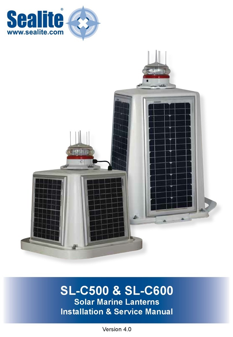
Sealite SLC600 Supplement

Sealite
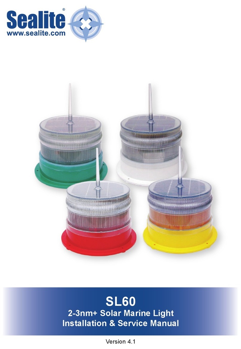
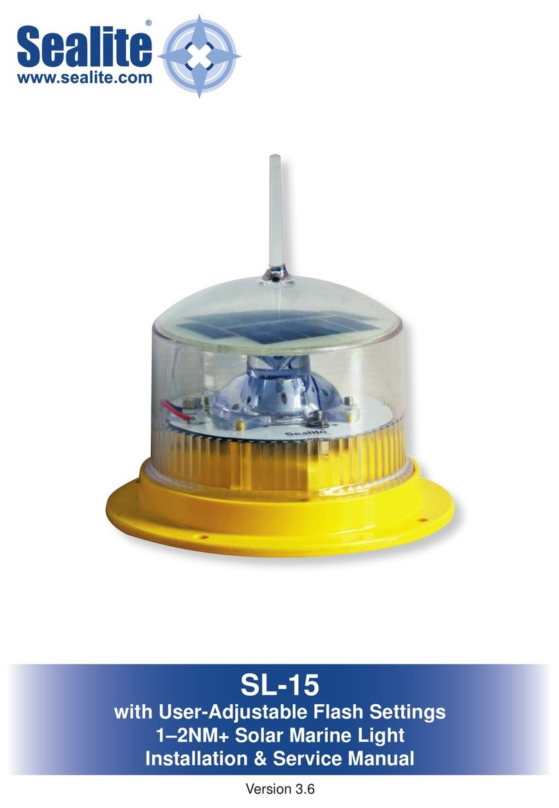
Sealite SL-15 Supplement

Sealite
Sealite SL-75 User manual

Sealite
Sealite SL-155 Series Supplement
Sealite
Sealite SL-75 Supplement