Sears Craftsman 351.183001 User manual

SAVE THIS
MANUAL FOR
FUTURE REFERENCE
OWNER'S
MANUAT
MODEL NO.
351 .183001
CAUTION:
Read and Follow AII
Safety Rules and
Operating I nstructions
Before First Use of
This Product.
ERRFTSMRiI
114" Crown Stapler
Safety lnstructions
Operation
Maintenance
Troubleshooting
Replacement Parts
SEARS, ROEBUCK AND CO., Hoffman Estates, lL 60179 U.S.A.@
Part No.6183.01 Aprit 1995

DESCRIPTION
The Sears Craftsman 1/4" Crown Stapler drives 1/4"
crown, 1B gauge staples from 112" to7lB" long. Die cast
aluminum, textured finish body minimizes operator fa-
tigue. Large capacity, top loading magazine with
positive, quick action latch makes loading staples easy.
Contact safety disables nailer, unless nose piece is in
contact with workpiece. Tapered nose piece provides
operator with greater visibility for precise staple place-
ment. Rigid nosepiece reduces jamming. Sears 1i4"
Crown Stapler is excellent for furniture making, uphol-
stering, cabinetry and picture framing.
SPECIFICATIONS
Capacity 100 staples
Staple crown width 114"
Staple lengths 112 to 7lB"
Staple size. . . . . 18 gauge (.049 x.040")
Operating pressure . 52-100 pSlG
Air inlet . . 1l4" F.N.P.T.
Length . .91t2"
Height. .2"
width . 2"
Weight 2.53 tbs.
STAPLES
918333 1l4" crown-1/2" long
918334 114" crown-3/4" long
918336 114" crown-7l8" long
SAFEW INSTRUCTIONS
. Air tool operators and all others in work area should
always wear safety goggles (must comply with ANSI
287.1) to prevent eye injury from fasteners and flying
debris when loading, operating or unloading this tool.
. Never^exceed operating pressure of 100 pSlG (7.1
kgicm3).
. Always keep hands and body away from the fastener
discharge area when air supply is connected to tool.
. Always disconnect tool from air supplywhen servicing
or adjusting tool and when tool is not in use.
. Do not operate tool when nose is not in contact with
work.
. Never load the tool until you are ready to use it.
. Never depress tool trigger when loading.
. Always load tool with nose pointing away from you
and others.
. Never point tool at yourself or others.
. Never carry tool with trigger depressed.
. Do not use oxygen, combustible gases or high pres-
sure compressed gas as the air supply for the tool.
o Always use tool at safe distance from other people in
work area.
. Do not attempt to discharge fastener into hard or
brittle materials such as concrete, steel or tile.
. Do not connect female quick-disconnect coupling to
tool side of air line.
. Connect male free-flow nipple to tool side of air line
so that tool is depressurized when disconnected from
hose.
. Use Sears recommended fasteners only.
OPERATING I NSTRUCTIONS
AIR SUPPLY LINE
Refer to Figure 1.
The Sears air stapler operates on compressed air at
pressures from 52 to 100 PSIG.
. Never exceed maxirnum pressure.
. Minimum air requirements for stapler: Average work-
ing SCFM 4.0 at 90 PSI with a B/8" air hose and 15
gallon tank.
WARNING: KEEP HANDS AND BODY AWAY FRGM
DISCHARGE AREA OF STAPLER WHEN
CONNECTING AIR SUPPLY.
ALWAYS DISCONNECT TOOL FROM
AIR SUPPLYWHEN SERVICING OR AD.
JUSTING TOOL AND WHEN TOOL tS
NOT IN USE.
. Clean dry air is essential to the operation of the Sears
stapler.
o Air operated tools require clean, dry, lubricated com-
pressed air to ensure top performance, low
maintenance and long life.
o Dirt and abrasive materials present in all air lines will
damage tool O-rings, valves and cylinders.
'FILTR - RE0ILATm - LUBRIiATIR /__ 2F0il- H0SE [HIp
v t\ \rffi
NI\
FEIIALE IUIIK _ 0,,*,*, -/ \- IIALE IUIIK - DISIOI{,JEII
Figure 1- Air Supply Line
_2-

AIR SUPPLY LINE (Continued)
r Moisture will reduce tool performance and life if not
removed from compressed air.
. A filter-regulator-lubricator system is required and
should be located as close to tool as possible (see
Figure 1).A distance of less than 15 feet is recom-
mended.
. Keep air filter clean. A dirty filter will reduce the air
pressure to the stapler causing a reduction in power
and efficiency.
o The air supply system must be able to provide air
pressure of 52 to 100 pounds per square inch at the
tool.
. The lubricator should be filled with a non-detergent air
tool oil
o All hoses and pipes in the air supply system must be
clean and free of all moisture and foreign particles.
. Never connect a female quick-disconnect coupling to
the tool side of air system. A male, free-flow coupling
should be connected to the tool side of air system.
The female coupling provides a seal preventing loss
of compressed air from compressor tank when dis-
connected from male coupling. lf connected to tool
side of air supply, the female coupling could seal a
compressed air charge in the stapler which could
discharge if the tool trigger is actuated.
. Do not mount swivel connector in air supply line.
o The air pressure should be properly regulated.
. Different workpiece materials and different staple
lengths will require different operating pressure.
. Be sure all connections in air supply system are
sealed to prevent air loss.
LOADING
Refer to Figures 2 & 5.
OPERATING INSTRUCTTONS (Continued)
WARNING: DISCONNECT TOOL FROM AtR SUP.
PLY, ALWAYS LOAD WITH NOSE
POINTING AWAY FROM YOU AND OTH.
ERS. ALWAYS WEAR SAFETY
GOGGLES THAT COMPLY WITH ANSI
z.87.1.
NOTE: For best results use Sears staples only.
Press latch handle (Key No. 38) fonruard to release
magazine cover (Key No. 49). lnsert staples into maga-
zine and slide magazine cover forward until latch snaps
into place, locking magazine cover.
STAPLING OPERATION
WARNING: NEVER OPERATE STAPLER UNLESS
NOSE OF TOOL IS IN CONTACT WITH
WORKPIECE. DO NOT OPERATE TOOL
WITHOUT STAPLES OR DAMAGE TO
TOOL MAY RESULT. NEVER FIRE STA.
PLES INTO AIR BECAUSE STAPLES
MAY INJURE OPERATOR OR OTHERS
AND DAMAGE TO TOOL MAY RESULT.
The Sears 1 14" Crown Stapler is equipped with a contact
trip safety mechanism (see Figure 3) that disables sta-
pler unless contacttrip is pushed againstwork. Hold tool
handle firmly and press nose of tool on workpiece where
staple is to be applied. Pull trigger to drive staple into
workpiece.
The stapler can also be operated by holciing trigger
depressed and pushing contact trip against workpiece.
This operating procedure provides rapidfire staple driv-
ing. Never operate tool unless contact trip is in contact
with workpiece.
Figure 2 - Loadino Staples
_'.?-
Figure 3 -Contact Trip Operation

OPERATING INSTRUCTIONS (Conti nued)
OPERATING PRESSURE
Use only enough air pressure to perform the stapling
operation. Air pressure in excess of that which is re-
quired will make the stapling operation inefficient and
may cause premature wear or damage to the tool.
Determine minimum air pressure required by driving
some test staples into the workpiece. Set air pressure
so that test staple crowns are driven down flush with the
work surface. Staples driven too deep may damage
workpiece.
EXHAUST PORT
Refer to Figures 4 & 5.
Exhaust port can be positioned at the left, front or right
side of tool. Reposition deflector (Key No. 6) by carefully
removing four socket head bolts (Key No.4)and rotating
deflector to desired position.
Be sure notto misplacevalve spring (Key No. 7). Secure
four socket head bolts, making sure that valve spring
and deflector are properly positioned.
Figure 4 - Exhaust Port Adiustment
MAINTENANCE
Refer To Figure 5.
Lubricate tool daily with quality air tool oil. lf no air line
lubricator is used, pour five to six drops of oil into inlet
(Key No. 3) of stapler everyday.
Keep magazine and nose clean and free of any dirt, lint
or abrasive particles.
The tip of the ram (Key No. 17) can become dented or
rounded over time. Square off the tip of the ram with a
clean, fine hand file to extend the life of the ram and
stapler. Staple firing will be more consistent if the ram
tip is kept clean and square.
lnspect contact trip safety mechanism daily for proper
operation.
Do not operate stapler if mechanism is not operating
properly.
Perform the following procedures to test safety mecha-
nism:
l.Leave trigger untouched while pushing contact trip
into workpiece. Stapler must not fire.
2.Pull stapler trigger while contact trip is clear of work
and pointed away from operator and others. Stapler
must not fire.
3.Depress and hold trigger. Push contact trip against
work where staple is needed. The stapler should drive
only one staple each time the contact trip is pushed
against workpiece.
lf contact trip mechanism does not operate properly,
repair stapler immediately through Seais Service Cen-
ter. Replace any damaged or missing parts. Use the
parts list to order parts.
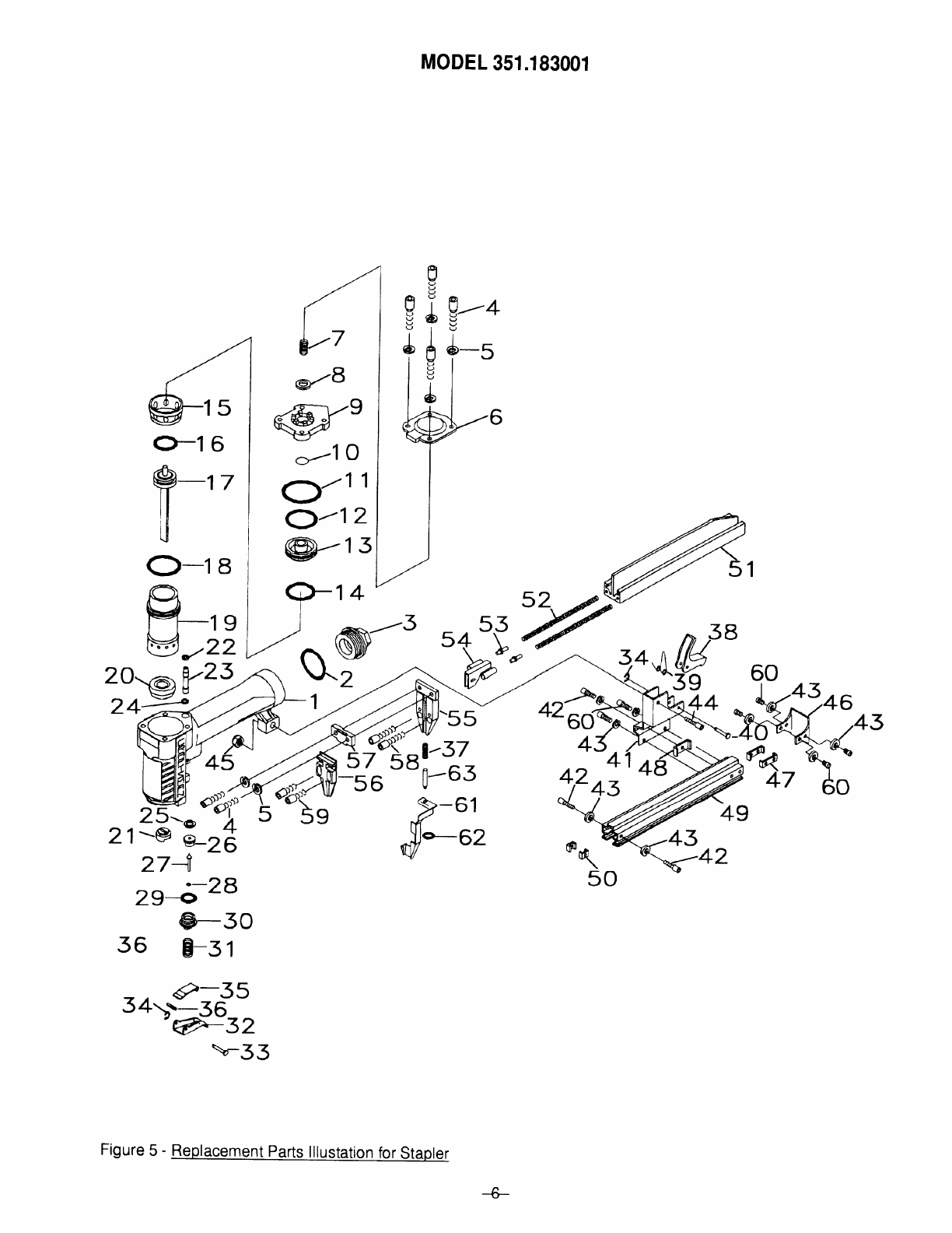
TROUBLESHOOTING
Refer to Figure 5.
WARNING: DISCONNECT TOOL FROM AIR SUP-
PLY BEFORE ATTEMPTING REPAIR OR
ADJUSTMENT.
lf staple jams in nose of tool, open magazine and
remove staples. Loosen two socket head bolts (Key No.
59) and remove nose cover (Key No. 56). Remove
jammed staple, replace nose cover and secure bolts.
lf tool will not fire or loses power, the O-rings may need
cleaning and lubrication. Remove deflector (Key No. 6)
and carefully remove cap, cylinder valve, piston, and
cylinder (Key Nos.9, 13, 17 &19). Clean all O-rings and
O-ring grooves with clean, dry cloth. Be careful not to
damage O-rings.
Replace O-rings if worn, stretched or damaged. Coat
O-rings and grooves with air tool oil. Assemble in re-
verse order of disassembiy.
lf tool trigger valve leaks, check O-rings (Key Nos. 25 &
28).
If ram fires but does not return, check piston O-ring (Key
No. 16).
lf tool leaks from under cap, check cap O-ring (Key No.
11).
lf tool leaks out of back of cap when trigger is depressed
and will not fire, check O-rings on tube (Key Nos. 22 &
24).
lf tool will not fire and leaks out of deflector, check
cylinder valve O-ring (Key No. 12).
FULL ONE YEAR WARRANW ON SEARSCRAFTSMAN 12'CROWN STAPLER
ll within one lull year lrom the date oI purchase this Sears Craltsman 1/2" Crown Stapler fails due to a
delect in material or workmanship, Sears will repair it lree ol charge.
WARRANW SERVICE IS AVAILABLE BY SIMPLY RETURNING THE STAPLER TO THE NEAREST SEARS
STORE OR SERVICE CENTER THROUGHOUTTHE UNITED STATES.
This warranty gives you specilic legal rights and you may have other rights which vary lrom state to state.
SEARS, ROEBUCK AND CO., DEPT. 817WA, HOFFMAN ESTATES, IL 60179
+
\\t

NOTES

o-1 6
@)-1 7
T"
O-ra
Fl--,n
V-zz
P rgf
zri6-3-rt
*8
(&;.e
-t3-
*1 O
U,.
O-1 2
@-1s
MODEL 351.193001
a-oo
4
*qr
7
g
&
I
d
g
L
P
J
7w-s
,u!-?
>-(
#'-'
lz ^<Rs-/J
,\ sy
\2 -,,',
1
-4
43
55
57
63
-61
-6:
3
;1
;2
tu.
47
49
zt4
zg-6-28
+-30
36 E-st
-. 9-35
5a;-56
-6>-32
\,-53
50
Figure 5 - Replacement Parts lllustation for Stapler
-6-
2o-@ Yzt
24*-
4,p
5
43
y-42

REPLACEMENT PARTS LIST FOR STAPLER
KEY
NO. PART
NO. DESCRIPTION QTY.
1
2
3
4
5
6042,00
6043,00
6044.00
6045.00
46-58494-3
Body
lnlet cap O-ring
Inlet cap
5-0.8 x 20mm Socket
Head Bolt.
5mm Lock Washer.
1
1
1
6
6
6
7
B
I
10
6046.00
6047.00
6048.00
6049.00
60s0.00
Deflector
Spring
Seal
cap
O-rinq (inside cao)
1
1
1
1
1
11
12
13
14
15
6051 .00
6052.00
6053.00
6054.00
6055.00
Cap O-ring
Valve piston O-ring
Cylinder valve piston
Piston seal
Deflector cylinder
1
1
1
1
1
16
17
18
19
20
6056.00
6266.00
6043.00
6059.00
6060.00
Piston O-ring
Piston-ram assembly
Cylinder O-ring
Cylinder
Bumper
1
1
1
1
1
21
22
23
24
25
6061 .00
6062.00
6063.00
6064.00
6065.00
Ram guide
Top O-ring
Tube
Bottom O-ring
Plastic seal
1
1
1
1
1
26
27
28
29
30
6066.00
6067.00
6068.00
6069.00
6070.00
Trigger valve head
Trigger valve stem
Stem O-ring
Guide O-ring
Triooer valve quide
1
1
1
1
1
31
32
33
6071.00
6187.00
6073.00
Spring
Trigger
Pin
1
1
1
KEY
NO, PART
NO. DESCRIPT!ON QTY.
34
35
36
37
38
39
46-22618-9
6074.00
6075.00
6100.00
6192.00
6193.00
2.5mm E-ring.
Trip Lever
Spring Pin
Spring
Latch
Latch Sprinq
2
1
1
1
1
1
40
41
42
43
6194.00
6195.00
6086.00
1904.00
Pin
Latch bracket
4mm-0.7 x 8mm Socket
Head Bolt.
4mm Lock Washer.
1
1
3
I
44
45
46
47
6197.00
6080.00
6199.00
6200.00
4-0.7 x 20mm Socket
Head Bolt.
4mm-0.7 Hex Nut.
Latch plate
Plate bracket
1
1
1
2
48
49
50
51
52
6201.00
6202.00
6203.00
6204.00
6205.00
Latch bracket plate
Magazine cover
Stop bracket
Magazine
Maqazine sprinq
1
1
2
1
2
53
54
55
56
57
6206.00
6207.00
6208.00
6209.00
6210.00
Spring rod
Pusher
Nose
Nose cover
Nose plate
2
1
JI
1
1
58
59
60
6097.00
6088.00
6279.00
4-0.7 x t4mm Socket
Head Bolt*
4-0.7 x 10mm Socket
Head Bolt.
4-0.7 x 1 2mm Flat Head
Socket Bolt.
2
2
6
61
62
63
o
8115.00
46-221138-9
6099.00
6183.01
Contact Trip
3mm E-ring.
Rod
Owner's Manual
1
1
1
1
*Standard hardware item available locally.
oNot shown.
RECOMM ENDED ACCESSORIES
Staples, 1/4" crown-1/2" long 91 8333
Staples, 1/4" crown-3/4" long 91 8334
Staples, 1/4" crown-7/8" long 91 8336
REBUILD KITS
o7849.00 Trigger Rebuild Kit,
Key Nos. 25,26,27,28 and 29 1
o7805.00 Cylinder Valve Rebuild Kit,
Key Nos. 10, 11 , 12 and 14 1
o7813.00 Piston Ram Rebuild Kit,
Key Nos. 16, 17,18 and 20 1
-7-

WEARS
OWNER'S
MANUAL
Mode! No.
351 .1 83001
To Call
Toll free
For Service:
1-800-4-REPAtR
(1 -800 -473-7247)
For Parts:
1.800-FON-PART
(1 -800-366-7 27 8)
ERRFTSMRII
114" Crown Stapler
The model number of your 1l4" Crown Stapler is found on the
front of the unit.
All repair parts are available for immediate purchase or special
order when you visit your nearest Sears Service Center, or the
Service Department at most Sears Stores. To request service or
order parts by phone, call the toll free numbers listed to the left.
When requesting service or ordering parts, always provide the
followi ng information :
Product Type: 114" Crown Stapler
Model Number: 351 .1 83001
Part Number
Part Description
SEARS, ROEBUCK AND CO., Holtman Estiates, lL 60i79 U.S.A.@
Part No.6183.01 April 1995
Table of contents
Other Sears Power Tools manuals

Sears
Sears Craftsman 113.239201 User manual

Sears
Sears 875.199190 User manual

Sears
Sears CRAFTSMAN User manual

Sears
Sears 149.23632 User manual

Sears
Sears 315.17470 User manual

Sears
Sears Craftsman 113.20680 User manual

Sears
Sears 103.23620 User manual

Sears
Sears Companion 919.19007 Configuration guide

Sears
Sears Craftsman 113.213850 User manual

Sears
Sears 875.188020 User manual