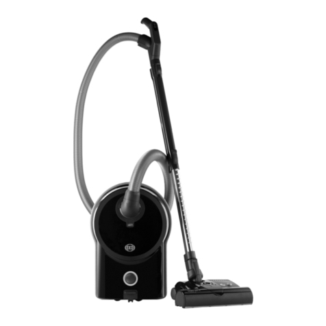
Sebo 470 Comfort User manual

Universalstaubsauger 470
electronic
Carpet Vacuum
Diese Informationen sind nur für Europa
bestimmt (230 V) und gelten nicht für
Nordameri a!
This information intended only for
Europe (230 V) and does not apply to
North America!

Universalstaubsauger 470 electronic
1 Griff
2 Stiel
3 Filterfüllanzeige
4 Schalter
5 Dec elschloß
6 Ausblasgitter
7 Dec el
8 Motordec el
9 Ele trobürste
10 Verriegelungs nopf
11 Rastpedal
12 Schlauch
13 Sicherungsring
14 Anschlußleitung
15 Handgriff des Teles opsaugrohres
16 Exzenterhebel
17 Griffmulde / Tragegriff
18 Leitungsha en
19 Teles opsaugrohr
20 Filtergehäuse
21 Fugendüse
22 Polsterdüse
23 Stell nopf
1 Handle grip
2 Handle assembly
3 Bag full indicator
4 On / Off switch
5 Co er release latch
6 Exhaust filter co er
7 Front co er
8 Motor co er
9 Power head
10 Locking catch
11 Foot pedal
12 Hose
13 Retaining ring
14 Cable
15 Attachment tube handle
16 Handle catch
17 Carrying handle
18 Cable hook
19 Attachment tube
20 Dust bag housing
21 Cre ice nozzle
22 Upholstery nozzle
23 Pile adjustment knob
Inbetriebnahme
Ele trobürste (9) auf ebene Unterlage
stellen, Gelen (26) und Gelen arm (27)
sen recht aufrichten. Verriegelungs nopf
(10) am Filtergehäuse (20) ca. 45° nach lin s
drehen, Filtergehäuse sen recht auf Gelen
und Gelen arm aufstec en und
Verrriegelungs nopf wieder nach rechts in
sen rechte Stellung drehen.
Für die Stielbefestigung den Exzenterhebel
(16) am Filtergehäuse(20) nach vorn drehen,
Stiel (2) in Aufnahme im Filtergehäuse
stec en bis der Stiel im Gehäusegrund
aufstößt, Exzenterhebel nach hinten drehen.
Teles opsaugrohr (19) in seitliche Gehäuse-
mulde einführen und nach unten in die
Gehäuseöffnung drüc en, der Handgriff des
Teles opsaugrohres (15) muß sich dabei
über den Noc en (24) schieben. Die
passende Schlauchseite in das Teles op-
saugrohr (19) einführen.
Zum Anschließen des Schlauches (12) an
das Filtergehäuse, das Ende mit der
schwarzen Buchse in die Verbindungshülse
(25) einführen und ganz einschieben. Zum
Lösen des Schlauchs den Sicherungsring
(13) an den Griffflächen zusammendrüc en.
1
2
3
4
5
6
7
8
9
10
11
12
13
14
15
16
17
18
19
20
21
22
23
Assembling the vacuum cleaner
Put the power head (9) on the floor with swi el
neck (26) and support le er (27) upright. Turn
the locking catch (10) on the filter bag housing
(20) to the left and place it carefully on the
swi el neck and the support le er. Then turn
the locking catch back.
To lock the handle turn the handle catch (16)
at the handle joint of the filter bag housing (20)
forward, then slide the handle assembly (2) in
as far as possible and lock it with the handle
catch.
Insert the attachment tube (19) into its storage
position on the side of the machine. The
attachment tube handle (15) must be placed
on the projection (24). Slide the proper end of
the hose into the tube (19).
To connect the hose with the filter bag housing
insert the black hose end into the connecting
tube (25) and slide it in completely. To unlock
the hose press the retaining ring (13) at the
projecting sections.
Carpet Vacuum
15
19
24
20
26
9
12
2
25
13
21
22
27

Inbetriebnahme / Preparation
Bürstenkontrolle
Die Bürsten ontrolle überwacht ständig die
Fun tion der Bürste.
Grün-Licht: Bürste arbeitet gut
Grün- und ot-Licht: Teppichbürste durch
Drehen des Stell nopfes (23) auf niedrigere
Zahl einstellen.
Bei Stellung 1.... und otlicht muß der
Bürstenstreifen gewechselt werden.
ot-Licht: Die Bürste wurde bloc iert oder
überlastet. Gerät ausschalten, Netzstec er
ziehen, Bürste auf Verunreinigung prüfen.
Filterfüllanzeige
Bei Aufleuchten der Kontrolleuchte (3) bitte
prüfen:
a) ist die Filtertüte voll ?
b) ist die Teppichbürste verstopft ?
c) ist der Saugschlauch verstopft ?
Entweder Filtertüte wechseln oder Verstop-
fung beseitigen. Es liegt eine Störung vor,
wenn beim Saugen mit dem Saugschlauch
das Handrohr verschlossen wird und die
Lampe aufleuchtet.
Gelenkraste
Die Gelen raste (11) arretiert den Universal-
sauger in sen rechter Ruhestellung, zum
Arbeiten Rastpedal treten und Gerät nach
hinten ippen.
Wartung / Maintenance
Filtertüten wechseln
Filtertüte bei Rotlicht (3) wechseln. Dec el-
schloß (5) - nach vorn ziehen und Dec el vom
Gehäuse abnehmen. Rastenlaschen seitlich
an der Filterplatte (28) zusammendrüc en und
die Filtertüte aus dem Filterhalter (29) ziehen.
Neue Filtertüte in die Führung des Filterhalters
einschieben und fest nach hinten drüc en.
Dec el wieder in das Gehäuse einhängen und
zu lappen, jetzt Dec elschloß schließen.
Motorschutzfilter wechseln
Motorschutzfilter (30, Art.-Nr. 1825) bei
Verschmutzung durch Aus lopfen reinigen.
Nach etwa 20 Filtertüten wechseln . Motor-
schutzfilter vorn in der Mitte leicht anheben
und aus der Führung ziehen. Anstelle des
Motorschutzfilters ist ein Hospital-Grade-
Mi rofilter erhältlich (Art.-Nr. 1875).
Abluftfilter wechseln
Den Abluftfilter (31, Art.-Nr. 1878) immer
zusammen mit dem Motorschutzfilter (30),
bzw. Mi rofilter wechseln. Dazu den Rast-
nopf (45) drüc enund das Ausblasgitter (6)
zur Seite abziehen.
Das Gerät niemals ohne Filter betreiben.
23
3
11
3
5 28
29
30
6
31
45
Brush controller
The electronic brush controller monitors the
operation of the brush.
Green light: Brush correctly set and running.
Green light and red light: Adjust the brush
setting by turning the Pile adjustment knob
(23) to a lower number.
If the lights still show at position number one
the brush strip is worn out and must be
replaced.
Red light: The brush has become blocked and
is not turning. Switch off. Unplug from the
outlet and clear the blockage.
Filter level indicator
If warning light (3) comes on check:
a) Is the dust bag full ?
b) Is there a blockage in the hose or power
head ?
Swivel neck latch
To release the machine from the upright
position depress the foot pedal (11)
Changing the paper bag
If red light (3) shows, change paper filter bag.
To do this first pull co er release latch (5) -
forward and lift the co er from the dust bag
housing. Slide the dust bag sealing plate (28)
from the holder (29). Slide the sealing plate
(28) of a new bag into the holder and push
firmly in. Insert co er into dust bag housing.
Push it forward then lock it in place by pushing
down the co er release latch.
Changing the motor filter
Motor filter (30, Art.-Nr. 1825) needs to be
replaced latest after the use of 20 filter bags.
Lift the front of the filter slightly and slide it out
of its slots. Instead of the motor filter a
‘Hospital-Grade‘-microfilter is a ailable
(Art.-Nr. 1875).
Changing the exhaust filter
Change the exhaust filter (31, Art.-Nr.1878)
always with the motor filter (30). Press the
button and slide the exhaust co er (6) to the
side.
Never use the machine without correctly
attached filters.

ACHTUNG - Bei allen Wartungs-
und einigungsarbeiten Gerät aus-
schalten und Netzstecker ziehen.
CAUTION - Always unplug machine
at mains outlet before dismantling
any part of machine.
Verstopfungen beseitigen
Verstopfungen im Schlauch werden entfernt,
in dem der Schlauch mit dem im Teles oprohr
befindlichen Ende in die Verbindungshülse (25)
gestec t wird. Das dann freie Ende einige
Male bei eingeschaltetem Gerät mit der
Handfläche verschließen und wieder frei
geben. Niemals versuchen den Pfropfen mit
einem Stab herauszudrüc en.
Borstenstreifen wechseln
Zum Borstenstreifenwechsel die Verschluß-
appe (32) von der Teppichbürste abschrau-
ben. Bürstenwalze so drehen, daß sich der
Borstenstreifen durch das seitliche Loch
herausschieben läßt. Neuen Borstenstreifen
ganz einschieben und Verschluß appe wieder
anschrauben.
Instandsetzung Maintenance
Clearing blockages
Bloc ages in the hose can cleared by ta ing
the hose off the machine and replacing it the
wrong way round in the connecting tube (25),
holding it upright with one hand bloc ing the
top and switching on the machine. If
necessary rapidly lift your hand on and off the
end of the hose.
Changing the brush strip
To replace brush strip: Remove brush strip
cover (32). Turn brush roller so that the brush
strip can then be pulled out. Ensure that the
new brush strip is fully inserted.
N.B. Replace the brush strip before the
bristles wear down to the level of the support
rod.
Zum Wechseln der Leiterplatte (43) die
3 Schrauben an der Saugrohrführung (42)
lösen und die Saugrohrführung abnehmen.
Anschlußleitungen lösen und Leiterplatte aus
der Führung ziehen.
Zum Öffnen des Motor opfes den Stoßschutz
(44) abziehen und die 4 Schrauben am
Motordec el (8) lösen.
Zum Öffnen der Teppichbürste die Verschluß-
appe (32) abschrauben. An der Unterseite
nur die 4 großen Schrauben lösen und dann
das Oberteil abziehen.
To remove the power head cover, ta e off the
brush strip cover (32) and remove the four
large screws from underneath the chassis. The
cover can then be lifted off.
25
32
42
43
8
44
32
To change the printed circuit board (43)
remove the 3 screws of the suction tube cover
(42). Inside release the wires and slide the
board out.
To get access to the suction motor remove the
dust bag housing bumper (44) and remove the
four screws on the motor cover (8).

Wechseln der Bürstenwalze:
Zahnriehmen (33) vom Motorritzel (34)
schieben, vier Schrauben an den Bürsten-
lagern lösen. Bürste von unten an beiden
Seiten gleichmäßig herausdrüc en.
Beim Einsetzen der Bürstenwalze beide Lager
gleichzeitig in die Führungsschlitze einsetzen
und gleichmäßig nach unten drüc en.
Lösen des Antriebsrades (35):
Zum Lösen Antriebsrad im Uhrzeigersinn
abdrehen.
Lösen des Motorritzels (36):
Schraubendreher mit breiter Klinge entgegen
dem Uhrzeigersinn an eine Zahnflan e setzen
und durch leichten Schlag mit dem Hammer
Ritzel von der Motorwelle lösen.
Bei ausgebautem Motor Motorwelle am
anderen Ende mit Schraubendreher festhalten.
Beim Einsetzen der Achse die Öse der
Drehfeder im Stift der Achse einhängen, den
geraden Schen el der Feder mit Zange greifen
und Feder in Pfeilrichtung spannen. Die Feder
so lange festhalten, bis die Achse richtig im
Unterteil eingesetzt ist.
Zum Herausnehmen des Gelen es (37) die
beiden Schrauben (38) an den Gelen lagern
(39) lösen und Gelen mit Gelen lagern aus
den Gehäuseschlitzen ziehen.
Beim Einbau des Gelen es darauf achten, daß
die Leitungen nicht gequetscht werden
önnen, auch nicht durch die anschließende
Montage des ET-Oberteiles.
Öffnen des Gelen es:
Die Schraube lösen und den Dec el (40) in
Pfeilrichtung schieben, dann herausheben.
Beim Zusammenbau darauf achten, daß die
Leitungen nicht gequetscht werden.
Auswechseln der Ele troni (41):
Die zum Motor führenden Leitungen aus der
Anschluß lemme lösen. Leiterplatte aus den
Führungsschlitzen ziehen und die vom Gelen
ommenden Leitungen von den Stec ern
abziehen.
Changing the brush roller:
Push the belt (33) off the motor pulley (34) and
remove the four screws which hold in the
brush bearing bloc s. Lift out the bearing
bloc s evenly. When replacing the roller with
the bearing bloc s, push downwards eeping
the roller parallel with the chassis.
To remove the brush roller pulley (35)
hold the roller in one hand and turn the pulley
in a cloc wise direction.
To remove the motor pulley (36)
insert a screwdriver into a groove and give a
light tap in an counter cloc wise direction. The
loosened pulley can then be removed.
To remove the axle assembly unscrew the
three screws and ta e off the axle clamps.
Before replacing, lightly grease the axle. To
replace, hoo one end of the spring on the
axle then grip the other end with a pair of
pliers and turn about a quarter of a turn.
Keeping the wheels at the ends of the axle
press the axle assembly bac into place.
To remove the swivel nec (37) ta e out the
two small screws (38) from the swivel nec
supports(39) then lift the swivel nec
assembly from the chassis. On re-assembly
chec that the wires from the swivel nec do
not become trapped when the power head
cover is replaced.
To remove the swivel nec cover
ta e out the retaining screw and slide the
cover (40) downwards then lift out. On re-
assembly chec that the wires do not become
trapped.
Changing the Electronic Controller (41):
Disconnect the lead from the motor. Lift the
controller upwards from the motor. Lift the
controller upwards from its location and then
disconnect the lead from the swivel nec .
34
33
36
35
37 39
38
40
41


Pos. Product- Description
Code
21 0850 dg Locking catch
22 1811 Locking rod
23 1012 N Terminal block
24 1807 hg Connector
25 1836 Female contact holder
26 1851 So nd ins lation
27 1047 Vac m motor seal
28 1844 Vac m motor 230 V (incl. Pos. 29 + 30)
1845 Vac m motor 240 V (incl. Pos. 29 + 30)
0511/1 Carbon br sh vac motor
29 1821 Motor cover
30 1822 S pport for Motor
31 1027 Leaf spring
32 1073 Clamp
33 1824 Connecting rod
34 1825 Vac m motor filter
35 1855 ER Printed circ it board 230 / 240 V
36 1860 Fitting
37 1852 hg S ction pipe cover
38 1869 hg Lens, bag light indicator
39 1830 dg Switch b tton
40 1862 Ret rn spring
41 1833 Internal cable
Pos. Product- Description
Code
42 1878 Exha st filter
43 1802 hg Exha st filter cover
44 1853 SE Motor cover
45 1804 hg D st bag ho sing b mper base
46 1846 hg Front cover cpl.
47 1818 dg Cover release
48 6040 Seal
49 1819 Cover
50 1847 Bag holder
51 5091 Safety catch spring
52 1817 Safety catch
53 5093 Paper bag (packed in 10)
54 5045 dg Extension t be witho t hose
55 5040 hg Hose
56 1491dg Upholstry nozzle
57 1092 dg Crevice nozzle
58 0102 Screw 3,9 x 13
59 0103 Screw 3,9 x 16
60 1875 Micro filter (Optional)
61 1884 hg Retaining b tton
Pos. Teile- Benennung
Nr.
1 1037 EH Griff (incl. Pos. 2)
2 1596 hg Griffabdeck ng
3 0127 Spiralformschra be M 4 x 10
4 1870 dg Anschl ßleit ng m. K-Stecker
1871 dg Anschl ßleit ng m. CH-Stecker
5 1848 Stiel
6 1831 hg Gehä se
7 1835 dg Abdeck ng, vorm.
(incl. Pos. 8 + 9)
8 5289 Dichtring
9 5043 Dichtring
10 5424 dg Sicher ngsring
11 1823 hg Z behörclip
12 5359 dg Kabeltülle
13 0502 Klemmleiste 2-pol.
14 1030 UL Z gentlast ngsschelle
15 1812 hg Deckel
16 1814 hg Kabelhakena fnahme
17 5146 Kabelhakenfeder
18 1813 hg Kabelhaken
19 1859 hg Exzenterhebel
20 0161 Sicher ngsscheibe
21 0850 dg Verriegel ngsknopf, kpl.
22 1811 Verriegel ngsstange
23 1012 N Kontaktsockel, kpl.
24 1807 hg Verbind ngsstück
25 1836 Kontakta fnahme, kpl.
26 1851 Schalldämm ngsmatte
27 1047 Gebläsedicht ng
28 1844 Gebläsemotor 230 V
(incl. Pos. 29 + 30)
0511/1 Kohlebürsten-Set
29 1821 Schalldämpfer
30 1822 Stützg mmi
31 1027 Blattfeder
32 1073 Lasche
33 1824 Motorfiltergestänge
34 1825 Motorfilter
35 1855 ER Leiterplatte 230 / 240 V
36 1860 Verbind ngsstück
37 1852 hg Sa grohrführ ng, vorm.
38 1869 hg Lampenabdeck ng, vorm.
39 1830 dg Schaltertaste
40 1862 Schenkelfeder
41 1833 Innenleit ng
42 1878 Abl ftfilter
43 1802 hg A sblasgitter
44 1853 SE Motordeckel, vorm.
45 1804 hg Stoßsch tz
46 1846 hg Deckel, kpl.
47 1818 dg Schließhebel
48 6040 Dicht ng
49 1819 Lagerdeckel
50 1847 Filterhalter, kpl.
51 5091 Drehfeder
52 1817 Sperrhebel
53 5093 Filtertüte
54 5045 dg Handsa grohr
55 5040 hg Schla ch
56 1491 dg Polsterdüse
57 1092 dg F gendüse
58 0102 Linsenblechschra be 3,9 x 13
59 0103 Linsenblechschra be 3,9 x 16
60 1875 Mikrofilter (Sonderz behör)
61 1884 hg Rastknopf
Pos. Product- Description
Code
1 1037 EH Handle grip (incl. Pos. 2)
2 1596 hg Handle grip back with grommet
3 0127 Screw Taptite M 4 x 10
4 1870 dg Cable with EU-Plug
1872 dg Cable with GB-Pl g
1873 dg Cable with ZA-Pl g
1874 hg Cable with AUS-Pl g
5 1848 Handle t be
6 1831 hg D st bag ho sing
7 1835 dg Internal cover
8 5289 Seal
9 5043 Seal
10 5424 dg Retaining ring
11 1823 hg Attachment clip
12 5359 dg Grommet
13 0502 Terminal block
14 1030 UL Cable clamp
15 1812 hg Cover
16 1814 hg Carrying handle
17 5146 Stop spring
18 1813 hg Cable hook
19 1859 hg Handle catch
20 0161 Clip 4 DIN 6799
55
19
54
35
37
38
39
51
52
40
49
48
47
50
53
36
43
42
61
41
46
44
45
58
60
1
2
3
4
5
12
15
58
17
16
59
14
13
18
20
9
7
10
8
58
6
11
57
21
56
31
32
33
58
34
26
27
28
29
30
23
22
24
25

Pos. Teile- Benennung
Nr.
101 4611 hg Unterteil
102 4004 ER Bodenleiste
103 4522 hg Stossbandage
104 4523 A hse
105 2528 or Rastpedal
106 2010 Drehfeder
107 2014 Las he
108 4603 hg Laufrolle
109 4006 Stella hse
110 2608 hg Stellrolle
111 4012 Stellhebel
112 2622 hg Stellknopf
113 4019 Zugfeder (Stellhebel)
114 4069 ER Bürstenmotor 230 V
0512/1 Kohlebürsten-Set (FHP)
05084 S Kohlebürsten-Set (Ametek)
115 2025 Zahnriemenritzel
116 4024 Zahnriemen
117 4605 hg Gelenk, kpl.
118 4606 Fla hste keraufnahme, kpl.
119 2602 hg Gelenkde kel
120 2467 Gelenklagerbu hse
121 0155 Paßs heibe
122 2613 Gelenklager
123 2453 S halterhalter
124 0531 Mikros halter
125 4601 S halthebel
126 4533 ER Leiterplatte 230 V
127 4033 ER Bürstenwalze mit Streifen
128 4028 Bürstenstreifen
129 2047 Loslager
130 2091 Festlager
131 2458 Antriebsrad
132 2629 hg Gelenkarm
133 2545 Drehfeder
134 4613 SE Oberteil, kpl.
135 2542 Vers hlusskappe
136 0111 TL Linsens hraube M 5 x 30
137 0102 Linsenble hs hraube 3,9 x 13
138 0103 Linsenble hs hraube 3,9 x 16
139 0105 Linsenble hs hraube 3,9 x 19
140 0174 Linsenble hs hraube 3,9 x 22
141 0141 Klemms heibe
Pos. Product- Description
Code
101 4611 hg Chassis
102 4004 ER Metal plate
103 4522 hg Bumper
104 4523 Axle
105 2528 or Foot pedal
106 2010 Axle spring
107 2014 Axle lamp
108 4603 hg Wheel
109 4006 Pile adjustment axle
110 2608 hg Pile adjustment wheel
111 4012 Pile adjustment lever
112 2622 hg Pile adjustment button
113 4019 Spring
114 4069 ER Brush motor 230 V
4070 ER Brush motor 240 V
0512/1 Carbon brush motor (FHP)
05084 S Carbon brush motor (Ametek)
115 2025 Motor pulley
116 4024 Drive belt
117 4605 hg Swivel ne k assembly
118 4606 Wire on swivel ne k, pl.
119 2602 hg Swivel ne k over
120 2467 Swivel ne k plasti bear
121 0155 Washer
Pos. Product- Description
Code
122 2613 Swivel support
123 2453 Mi ro swit h support
124 0531 Mi ro swit h
125 4601 Swit h lever
126 4533 ER Ele troni ontroller 230 V
4534 ER Ele troni ontroller 240 V
127 4033 ER Brush assembly
128 4028 Brush strip
129 2047 Bearing blo k R.H.
130 2091 Bearing blo k L.H.
131 2458 Brush roller pulley
132 2629 hg Support lever
133 2545 Return spring
134 4613 SE Cover, pl.
135 2542 Brush strip over
136 0111 TL S rew M 5 x 30
137 0102 S rew 3,9 x 13
138 0103 S rew 3,9 x 16
139 0105 S rew 3,9 x 19
140 0174 S rew 3,9 x 22
141 0141 Washer
134
121
120
118
117
139
114
140
120
121
137
141
122
115
116
131
130
126
132
133
105
104
106
108
107
137
136
110
107
137
135
137
141
125
124
137
141
123
119
137
138
129
128
127
103
138
112
138
113
101
102
108
136
111
107
137
110
109
Other manuals for 470 Comfort
1
Table of contents
Other Sebo Vacuum Cleaner manuals
Sebo
Sebo Automatic X5 User manual
Sebo
Sebo Automatic XP2 User manual

Sebo
Sebo AIRBELT K User manual
Sebo
Sebo Automatic X1 User manual
Sebo
Sebo EVOLUTION 320 User manual
Sebo
Sebo Automatic X4 User manual

Sebo
Sebo ET-1 User manual
Sebo
Sebo PROFESSIONAL D9 User manual
Sebo
Sebo Dart User manual

Sebo
Sebo XP 20 User manual

Sebo
Sebo automatic X Series User manual
Sebo
Sebo Dart User manual
Sebo
Sebo Power Head 350e User manual
Sebo
Sebo automatic X Series User manual

Sebo
Sebo BS 36 Comfort User manual

Sebo
Sebo Dart User manual
Sebo
Sebo Airbelt D User manual

Sebo
Sebo 370 comfort User manual
Sebo
Sebo Professional G1 Instruction manual
Sebo
Sebo ESSENTIAL G Installation guide
