Sebo 370 comfort User manual
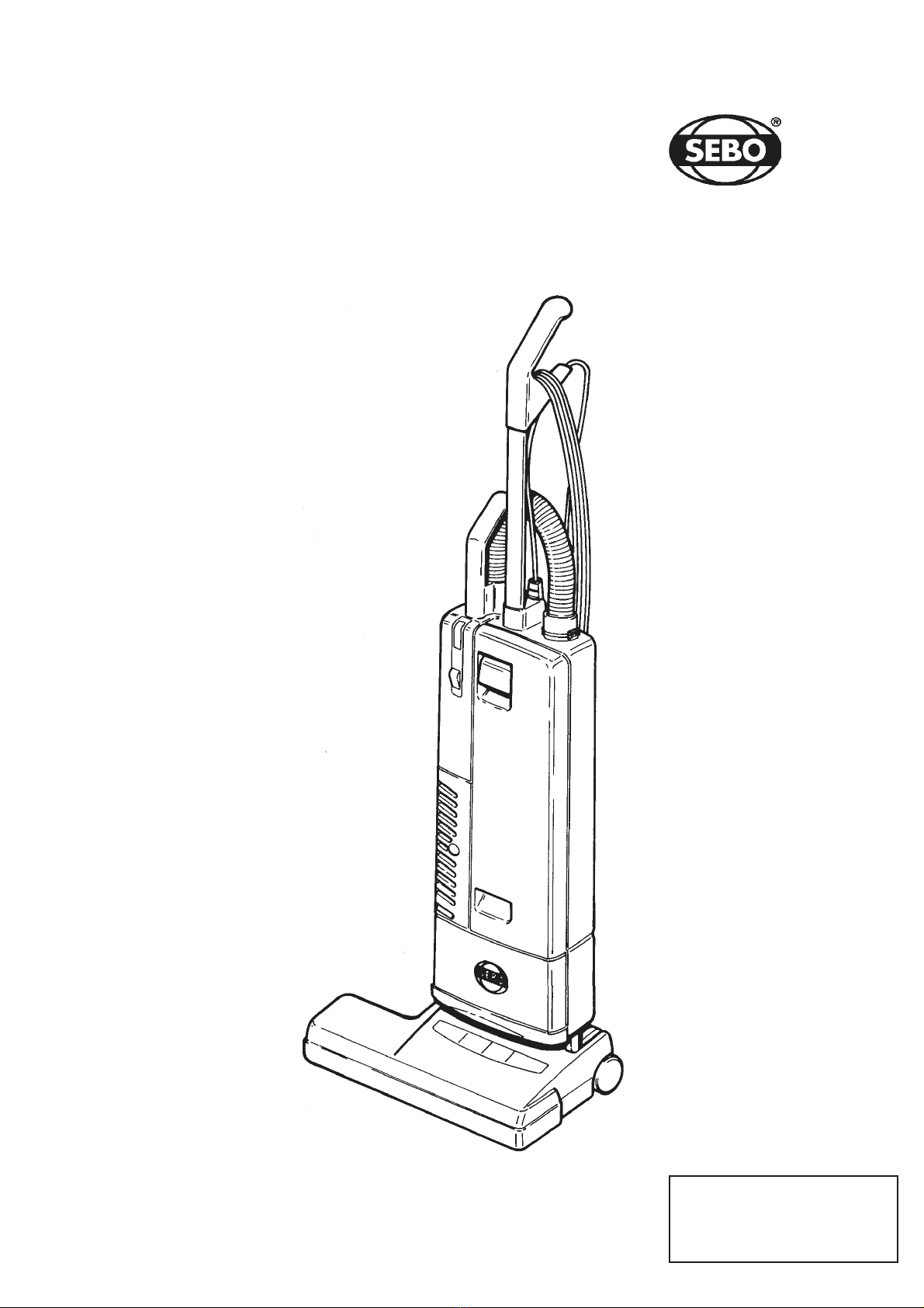
Universalstaubsauger 370
Carpet Vacuum electronic
Diese Informationen sind nur für Europa
bestimmt (230 V) und gelten nic t für
Nordamerika!
T is information intended only for
Europe (230 V) and does not apply to
Nort America!

Universalstaubsauger 370 electronic
Carpet Vacuum
1Griff
2 Stiel
3 Filterfüllanzeige
Schalter
5 Deckelschloß
6 Ausblasgitter
7 Deckel
8 Motordeckel
9 Elektrobürste
10 Verriegelungsknopf
11 Rastpedal
12 Schlauch
13 Sicherungsring
1 Anschlußleitung
15 Handgriff des Teleskopsaugrohres
16 Exzenterhebel
17 Griffmulde / Tragegriff
18 Leitungshaken
19 Teleskopsaugrohr
20 Filtergehäuse
21 Fugendüse
22 Polsterdüse
23 Stellknopf
1 Handle grip
2 Handle assembly
3 Bag full indicator
On / Off switch
5 Cover release latch
6 Exhaust filter cover
7 Front cover
8 Motor cover
9 Power head
10 Locking catch
11 Foot pedal
12 Hose
13 Retaining ring
1 Cable
15 Attachment tube handle
16 Handle catch
17 Carrying handle
18 Cable hook
19 Attachment tube
20 Dust bag housing
21 Crevice nozzle
22 Upholstery nozzle
23 Pile adjustment knob
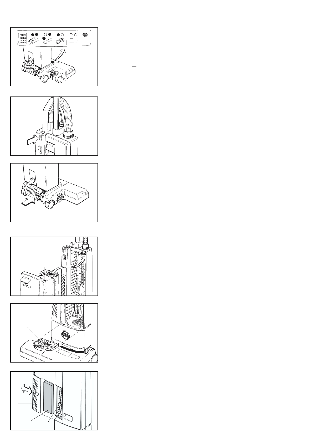
Inbetriebnahme
Elektrobürste (9) auf ebene Unterlage
stellen, Gelenk (26) und Gelenkarm (27)
senkrecht aufrichten. Verriegelungsknopf
(10) am Filtergehäuse (20) ca. 5° nach
links drehen, Filtergehäuse senkrecht auf
Gelenk und Gelenkarm aufstecken und
Verrriegelungsknopf wieder nach rechts in
senkrechte Stellung drehen.
Für die Stielbefestigung den Exzenterhebel
(16) am Filtergehäuse(20) nach vorn
drehen, Stiel (2) in Aufnahme im Filter-
gehäuse stecken bis der Stiel im Gehäuse-
grund aufstößt, Exzenterhebel nach hinten
drehen.
Teleskopsaugrohr (19) in seitliche Gehäuse-
mulde einführen und nach unten in die
Gehäuseöffnung drücken, der Handgriff des
Teleskopsaugrohres (15) muß sich dabei
über den Nocken (2 ) schieben. Die
passende Schlauchseite in das Teleskop-
saugrohr (19) einführen.
Zum Anschließen des Schlauches (12) an
das Filtergehäuse, das Ende mit der
schwarzen Buchse in die Verbindungshülse
(25) einführen und ganz einschieben. Zum
Lösen des Schlauchs den Sicherungsring
(13) an den Griffflächen zusammendrücken.
1
2
3
4
5
6
7
8
9
10
11
15
19
24
20
26
9
12
2
25
13
27
12
13
14
15
16
17
18
19
20
21
22
23
Assembling the vacuum cleaner
Put the power head (9) on the floor with swivel
neck (26) and support lever (27) upright. Turn
the locking catch (10) on the filter bag housing
(20) to the left and place it carefully on the
swivel neck and the support lever. Then turn
the locking catch back.
To lock the handle turn the handle catch (16)
at the handle joint of the filter bag housing
(20) forward, then slide the handle assembly
(2) in as far as possible and lock it with the
handle catch.
Insert the attachment tube (19) into its storage
position on the side of the machine. The
attachment tube handle (15) must be placed
on the projection (2 ). Slide the proper end of
the hose into the tube (19).
To connect the hose with the filter bag housing
insert the black hose end into the connecting
tube (25) and slide it in completely. To unlock
the hose press the retaining ring (13) at the
projecting sections.
Inbetriebnahme / Preparation
Bürstenkontrolle
Die Bürstenkontrolle überwacht ständig die
Funktion der Bürste.
Grün-Lic t: Bürste arbeitet gut
Grün- und Rot-Lic t: Teppichbürste durch
Drehen des Stellknopfes (23) auf niedrigere
Zahl einstellen.
Bei Stellung 1.... und Rotlic t muß der
Bürstenstreifen gewechselt werden.
Rot-Lic t: Die Bürste wurde blockiert oder
überlastet. Gerät ausschalten, Netzstecker
ziehen, Bürste auf Verunreinigung prüfen.
Filterfüllanzeige
Bei Aufleuchten der Kontrolleuchte (3) bitte
prüfen:
a) ist die Filtertüte voll ?
b) ist die Teppichbürste verstopft ?
c) ist der Saugschlauch verstopft ?
Entweder Filtertüte wechseln oder Verstop-
fung beseitigen. Es liegt keine Störung vor,
wenn beim Saugen mit dem Saugschlauch
das Handrohr verschlossen wird und die
Lampe aufleuchtet.
Gelenkraste
Die Gelenkraste (11) arretiert den Universal-
sauger in senkrechter Ruhestellung, zum
Arbeiten Rastpedal treten und Gerät nach
hinten kippen.
Wartung / Maintenance
Filtertüten echseln
Filtertüte bei Rotlicht (3) wechseln. Deckel-
schloß (5) - nach vorn ziehen und Deckel vom
Gehäuse abnehmen. Rastenlaschen seitlich
an der Filterplatte (28) zusammendrücken und
die Filtertüte aus dem Filterhalter (29) ziehen.
Neue Filtertüte in die Führung des Filterhalters
einschieben und fest nach hinten drücken.
Deckel wieder in das Gehäuse einhängen und
zuklappen, jetzt Deckelschloß schließen.
Motorschutzfilter echseln
Motorschutzfilter (30, Art.-Nr. 1825) bei
Verschmutzung durch Ausklopfen reinigen.
Nach etwa 20 Filtertüten wechseln . Motor-
schutzfilter vorn in der Mitte leicht anheben
und aus der Führung ziehen. Anstelle des
Motorschutzfilters ist ein Hospital-Grade-
Mikrofilter erhältlich (Art.-Nr. 1875).
Abluftfilter echseln
Den Abluftfilter (31, Art.-Nr. 1878) immer
zusammen mit dem Motorschutzfilter (30),
bzw. Mikrofilter wechseln. Dazu den Rastknopf
( 5) drückenund das Ausblasgitter (6) zur
Seite abziehen.
Das Gerät niemals ohne Filter betreiben.
23
3
11
3
5 28
29
30
6
31
Brush controller
The electronic brush controller monitors the
operation of the brush.
Green lig t: Brush correctly set and running.
Green lig t and red lig t: Adjust the brush
setting by turning the Pile adjustment knob
(23) to a lower number.
If the lights still show at position number one
the brush strip is worn out and must be
replaced.
Red lig t: The brush has become blocked and
is not turning. Switch off. Unplug from the
outlet and clear the blockage.
Filter level indicator
If warning light (3) comes on check:
a) Is the dust bag full ?
b) Is there a blockage in the hose or power
head ?
S ivel neck latch
To release the machine from the upright
position depress the foot pedal (11)
Changing the paper bag
If red light (3) shows, change paper filter bag.
To do this first pull cover release latch (5) -
forward and lift the cover from the dust bag
housing. Slide the dust bag sealing plate (28)
from the holder (29). Slide the sealing plate
(28) of a new bag into the holder and push
firmly in. Insert cover into dust bag housing.
Push it forward then lock it in place by pushing
down the cover release latch.
Changing the motor filter
Motor filter (30, Art.-Nr. 1825) needs to be
replaced latest after the use of 20 filter bags.
Lift the front of the filter slightly and slide it out
of its slots. Instead of the motor filter a
‘Hospital-Grade‘-microfilter is available
(Art.-Nr. 1875).
Changing the exhaust filter
Change the exhaust filter (31, Art.-Nr.1878)
always with the motor filter (30). Press the
button and slide the exhaust cover (6) to the
side.
Never use the machine ithout correctly
attached filters.
45

ACHTUNG - Bei allen Wartungs-
und Reinigungsarbeiten Gerät aus-
schalten und Netzstecker ziehen.
CAUTION - Al ays unplug machine
at mains outlet before dismantling
any part of machine.
Verstopfungen beseitigen
Verstopfungen im Schlauch werden entfernt,
in dem der Schlauch mit dem im Teleskoprohr
befindlichen Ende in die Verbindungshülse
(25) gesteckt wird. Das dann freie Ende einige
Male bei eingeschaltetem Gerät mit der
Handfläche verschließen und wieder frei
geben. Niemals versuchen den Pfropfen mit
einem Stab herauszudrücken.
Borstenstreifen echseln
Zum Borstenstreifenwechsel die Verschluß-
kappe (32) von der Teppichbürste abschrau-
ben. Bürstenwalze so drehen, daß sich der
Borstenstreifen durch das seitliche Loch
herausschieben läßt. Neuen Borstenstreifen
ganz einschieben und Verschlußkappe wieder
anschrauben.
Instandsetzung Maintenance
Clearing blockages
Blockages in the hose can cleared by taking
the hose off the machine and replacing it the
wrong way round in the connecting tube (25),
holding it upright with one hand blocking the
top and switching on the machine. If
necessary rapidly lift your hand on and off the
end of the hose.
Changing the brush strip
To replace brush strip: Remove brush strip
cover (32). Turn brush roller so that the brush
strip can then be pulled out. Ensure that the
new brush strip is fully inserted.
Replace the brush strip before the bristles
wear down to the level of the support rod.
Zum Wechseln der Leiterplatte ( 3) die
3 Schrauben an der Saugrohrführung ( 2)
lösen und die Saugrohrführung abnehmen.
Anschlußleitungen lösen und Leiterplatte aus
der Führung ziehen.
Zum Öffnen des Motorkopfes den Stoßschutz
( ) abziehen und die Schrauben am
Motordeckel (8) lösen.
Zum Öffnen der Teppichbürste die Verschluß-
kappe (32) abschrauben. An der Unterseite
nur die großen Schrauben lösen und dann
das Oberteil abziehen.
To remove the power head cover, take off the
brush strip cover (32) and remove the four
large screws from underneath the chassis.
The cover can then be lifted off.
25
32
42
43
8
44
32
To change the printed circuit board ( 3)
remove the 3 screws of the suction tube cover
( 2). Inside release the wires and slide the
board out.
To get access to the suction motor remove the
dust bag housing bumper ( ) and remove the
four screws on the motor cover (8).

Wechseln der Bürstenwalze:
Zahnriehmen (33) vom Motorritzel (3 )
schieben, vier Schrauben an den Bürsten-
lagern lösen. Bürste von unten an beiden
Seiten gleichmäßig herausdrücken.
Beim Einsetzen der Bürstenwalze beide Lager
gleichzeitig in die Führungsschlitze einsetzen
und gleichmäßig nach unten drücken.
Lösen des Antriebsrades (35):
Zum Lösen Antriebsrad im Uhrzeigersinn
abdrehen.
Lösen des Motorritzels (36):
Schraubendreher mit breiter Klinge entgegen
dem Uhrzeigersinn an eine Zahnflanke setzen
und durch leichten Schlag mit dem Hammer
Ritzel von der Motorwelle lösen.
Bei ausgebautem Motor Motorwelle am
anderen Ende mit Schraubendreher festhal-
ten.
Beim Einsetzen der Achse die Öse der
Drehfeder im Stift der Achse einhängen, den
geraden Schenkel der Feder mit Zange
greifen und Feder in Pfeilrichtung spannen.
Die Feder so lange festhalten, bis die Achse
richtig im Unterteil eingesetzt ist.
Zum Herausnehmen des Gelenkes (37) die
beiden Schrauben (38) an den Gelenklagern
(39) lösen und Gelenk mit Gelenklagern aus
den Gehäuseschlitzen ziehen.
Beim Einbau des Gelenkes darauf achten,
daß die Leitungen nicht gequetscht werden
können, auch nicht durch die anschließende
Montage des ET-Oberteiles.
Öffnen des Gelenkes:
Die Schraube lösen und den Deckel ( 0) in
Pfeilrichtung schieben, dann herausheben.
Beim Zusammenbau darauf achten, daß die
Leitungen nicht gequetscht werden.
Auswechseln der Elektronik ( 1):
Die zum Motor führenden Leitungen aus der
Anschlußklemme lösen. Leiterplatte aus den
Führungsschlitzen ziehen und die vom Gelenk
kommenden Leitungen von den Steckern
abziehen.
Changing the brush roller:
Push the belt (33) off the motor pulley (3 )
and remove the four screws which hold in the
brush bearing blocks. Lift out the bearing
blocks evenly. When replacing the roller with
the bearing blocks, push downwards keeping
the roller parallel with the chassis.
To remove the brush roller pulley (35)
hold the roller in one hand and turn the pulley
in a clockwise direction.
To remove the motor pulley (36)
insert a screwdriver into a groove and give a
light tap in an counter clockwise direction. The
loosened pulley can then be removed.
To remove the axle assembly unscrew the
three screws and take off the axle clamps.
Before replacing, lightly grease the axle. To
replace, hook one end of the spring on the
axle then grip the other end with a pair of
pliers and turn about a quarter of a turn.
Keeping the wheels at the ends of the axle
press the axle assembly back into place.
To remove the swivel neck (37) take out the
two small screws (38) from the swivel neck
supports(39) then lift the swivel neck
assembly from the chassis. On re-assembly
check that the wires from the swivel neck do
not become trapped when the power head
cover is replaced.
To remove the swivel neck cover
take out the retaining screw and slide the
cover ( 0) downwards then lift out. On re-
assembly check that the wires do not become
trapped.
Changing the Electronic Controller ( 1):
Disconnect the lead from the motor. Lift the
controller upwards from the motor. Lift the
controller upwards from its location and then
disconnect the lead from the swivel neck.
34
33
36
35
37 39
38
40
41
2
1
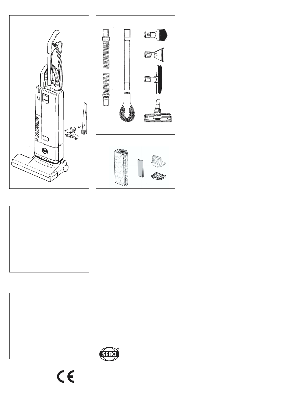
A Zubehör
11 91 Polsterdüse
21092 Fugendüse
B Sonderzubehör
11 95 Verlängerungsschlauch
2108 Verlängerungsrohr
3109 Staubpinsel
41090 Flachposterdüse
51325 Wand- und Polsterbürste
61383 Kombi-Bodendüse
71 96 Heizkörperpinsel
C Service -Teile
15093 Filtertüte
21878 Abluftfilter
31825 Motorfilter
41875 Mikrofilter
A Attachments
11 91 Upholstery Nozzle
21092 Crevice Nozzle
B Optional Attachments
11 95 Extension Hose
2108 Straight Tube
3109 Dusting Brush
41090 Upholstery Nozzle, special
51325 Wall- and Floor Brush
61383 Combination Nozzle
71 96 Radiator Brush
C Service Parts
15093 Paper Bag
21878 Exhaust Filter
31825 Vacuum Motor Filter
41875 Micro Filter
A selection of attachments is available as a kit
Gebläsemotor 1000 Watt
Unterdruck 200 mbar
Luftmenge 55 dm3 / s
Filtertüte 5,3 dm3, 3-lagig
Bürstenmotor 150 Watt
Arbeitsbreite 325 mm
Borstenstreifen auswechselbar
Bürstenantrieb Zahnriemen mit
elektrischem
Überlastungsschutz
Höhe 1225 mm
Breite 360 mm
Gewicht 8 kg
Schutzklasse II doppelt isoliert
Technische Daten
Arbeiten an der elektrischen Installation dürfen
nur von Sachkundigen ausgeführt erden !
Technical Details
Vacuum motor 1000 Watt
Air flow 55 l / s
Dust bag 5,3 litres, 3-layer
Brush motor 150 Watt
Brush width 325 mm
Brush drive non slip drive belt
with electronic
overload protection
Brush strip replaceable
Height 1225 mm
Width 360 mm
Weight 8 kg
Protection double insulanted
For serving please contact your supplier or the
address belo .
A B
C
ACHTUNG - Hin eis zur Sicherheit
- elektrisches Gerät, vor Wasser und
Feuchtigkeit schützen,
- gemäß der Anschlußwerte des Typen-
schildes anschließen und betreiben,
- nur zur Reinigung trockener Flächen,
- nichts Glühendes oder Heißes aufsaugen,
- niemals bei angeschlossenem oder laufen-
dem Gerät an die Bürste fassen,
- Benutzung durch Kinder nur unter Aufsicht,
- Menschen oder Tiere nicht absaugen,
- Gerät mit Defekten nicht anschließen,
- wenn das Gerät selbst abschaltet, erst aus-
schalten, dann Netzstecker ziehen und erst
dann die Ursache beseitigen,
- bei allen Arbeiten am Gerät, ausschalten,
und Netzstecker ziehen,
- nach der Benutzung den Netzstecker ziehen,
- keine Schrauben lösen, Arbeiten im Geräte-
inneren nur durch Fachkräfte,
- Garantieleistungen nur bei Verwendung von
Original SEBO Ersatz- und Verschleißteilen,
- Benutzung auf eigene Verantwortung, der
Hersteller kann für Schäden durch die Benut-
zung nicht verantwortlich gemacht werden.
- gemäß der Gebrauchsanweisung benutzen
und deren spezielle Hinweise beachten.
CAUTION - Safety advice
Do not re-use bags.
Do not wash filters.
Do not vacuum hot material eg. ash.
Do not leave machine near heat source eg.
fires, ovens, radiators.
Do not remove any screws.
ELECTRICAL APPLIANCE:
Disconnect from mains before maintenance,
changing brush, bag and filters.
Keep away from liquid or moisture.
Vacuum dry surfaces only.
Do not use with a damaged cable.
Fit only 10 amp fuse.
THIS APPLIANCE HAS A ROTATING BRUSH:
Do not run over mains cable.
Do not leave plugged in and unattended.
Children and pets must be strictly supervised
during use. Ensure machine is in upright position
and the brush is above floor level when using the
hose.
Do not tilt the brush head on to the floor when
using the hose. This can cause marking.
Do not place brush head over rug / carpet edges.
Some floor coverings may be damaged by
upright vacuums eg. wool loop carpets and
cushion vinyl. Check with flooring supplier before
use and treat with care.
IT IS THE USERS RESPONSIBILITY TO OPERATE
THIS APPLIANCE IN ACCORDANCE WITH THE
OPERATING INSTRUCTIONS.
PLEASE READ AND RETURN GUARANTEE CARD.
Diese Informationen sind nur für Europa
bestimmt (230 Volt) und gelten nicht für
Nordamerika !
This information is intended only for Europe
(230 V) and does not apply to North America !
4
1 2
3
3
4
5
6
STEIN & COSTEIN & CO
STEIN & COSTEIN & CO
STEIN & CO
GMBH
2553 VELBERT . WÜLFRATHER STRASSE 7- 9
TELEFON (0 20 53) 89 81 . FAX (0 20 53) 89 85
BODENPFLEGE
GERÄTE + SYSTEME
06252 D - 07/2001
1 2
7
Other manuals for 370 comfort
7
Table of contents
Other Sebo Vacuum Cleaner manuals

Sebo
Sebo AIRBELT D4 Installation guide

Sebo
Sebo Airbelt D User manual

Sebo
Sebo BS 36 Comfort User manual

Sebo
Sebo Dart User manual

Sebo
Sebo Dart User manual

Sebo
Sebo Airbelt K3 User manual

Sebo
Sebo G-SERIES User manual

Sebo
Sebo essential G-Series Instruction manual

Sebo
Sebo Power Head 350e User manual

Sebo
Sebo 370 comfort User manual

Sebo
Sebo Automatic X5 User manual

Sebo
Sebo Dart User manual

Sebo
Sebo Felix Premium User manual

Sebo
Sebo Automatic X4 User manual

Sebo
Sebo Professional D User manual

Sebo
Sebo Airbelt D User manual

Sebo
Sebo AUTOMATIC X Series User manual

Sebo
Sebo AIRBELT K User manual

Sebo
Sebo XP 20 User manual

Sebo
Sebo Felix Premium User manual


