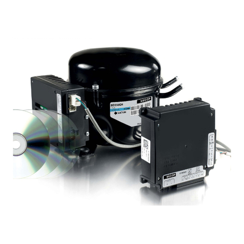
SECOP 101N07 Series User manual

CONTROLLER FOR
BD COMPRESSORS
Flexible control settings
TOOL COOL
4
OPERATING INSTRUCTIONS
101N07xx Series, 48 V DC
WE HAVE MORE THAN 30
YEARS OF EXPERIENCE,
DEVELOPING DIRECT
CURRENT COMPRESSORS
AND HELPING CUSTOMERS
BENEFIT FROM THE
OPPORTUNITIES OF
MOBILE REFRIGERATION
TECHNOLOGY.
WITH A DEEP INSIGHT OF
THE USAGE ACROSS VARIOUS
APPLICATIONS WE HAVE
EARNED A POSITION AS
MARKET LEADER, WORKING
WITH OEM-CUSTOMERS .
www.secop.com SETTING THE STANDARD

2
Operating
Instructions

Operating
Instructions
3
Operating
Instructions
3
1. Introduction ..............................................................................................5
1.1 Applications............................................................................................5
1.2 Capability................................................................................................5
1.3 Functions................................................................................................5
1.4 Programming Interface .........................................................................5
2. Installation ..............................................................................................6
2.1 Checklist ................................................................................................6
2.2 Connect Cables ......................................................................................7
2.3 Install and Configure Software ..............................................................9
3. TOOL4COOL
®
Software Interface ............................................................. 15
3.1 User Interface ......................................................................................15
3.2 Operation ..............................................................................................15
4. Parameters ............................................................................................ 16
4.1 Parameter Overview ............................................................................16
4.2 Description of Parameters ..................................................................18
5. Ordering ............................................................................................ 26
TABLE OF CONTENTS

4
Operating
Instructions

Operating
Instructions
5
1.
INTRODUCTION
The cooling capacities of the compressors are approx. 480 Watt (BD250GH.2) and 900 Watt
(BD350GH) @ Pe/Pc ~+15/+55°C
The system is able to operate in ambient temperatures up to +55 ºC (131 F).
The operating conditions are High Back Pressure (HBP).
The main functions of the controllers are:
• Motor / Compressor speed control
• Thermostat control (ON / OFF or electronic via NTC temperature sensor)
• ECO function to optimize compressor speed for minimum power consumption
• Condenser fan control
• Evaporator fan control
• Communication interface
• Monitoring function
• Error & event log
• Battery protection functions
• Main Switch
• Log of specific parameters
• Optimization of specific parameters via PC software before commencing mass production
The controller can be accessed using either
• The Secop software tool, Tool4Cool
®
LabEdition, or
• A custom interface. Please contact Secop for further information regarding custom interfaces.
The BD 48 V DC compressor systems are intended mainly for shelter cooling and cooling of bat-
teries in radio stations for cellular phones.
Secondary applications could be
• Spot cooling in golf carts, forklifts, etc
• Air cargo cooling
1.1
Applications
1.2
Capability
1.3
Functions
1.4
Programming
Interface

6
Operating
Instructions
BD electronic controller
101N07xx Series 48V DC
• 101N0720 or
• 101N0732
Tool4Cool
®
LabEdition software download:
www.secop.com/tool4cool.html
NTC temperature sensor
(alternative: mechanical thermostat)
Product key for BD compressor controller - on request -
Secop One Wire/LIN gateway with
connection cables
• Gateway
• One Wire/LIN gateway
communication cable
• USB 2.0 A/B cable
2.
INSTALLATION
Installation involves the following steps:
• Checklist
• Cable connection
• Software installation and configuration
2.1
Checklist
Ordering: See section 5
Check that you have the following:

Operating
Instructions
7
Wiring diagram 101N0732 and 101N0720 (below)
2.2
Connect Cables

8
Operating
Instructions
Wire dimensions
The compressor control unit has the following connections:
I, C, + Modbus data communication. I = communication C & + power supply.
C, T Thermostat connection. A Secop NTC temperature sensor (option 2) can be connected
or a mechanical ON/OFF thermostat (option 1)
Fe, + Evaporator fan (Optional) 48 V DC, 32-60 V, max 60 Watt power output, pulse width
modulated.
Fc, + Condenser fan (optional) 48 V DC, 32-60 V max, 60 Watt power output, pulse width
modulated.
-, + Main supply voltage. Nominal voltage 48 V DC, range: 32 to 60 V DC
* Length between battery and electronic unit
Size Max. length*
48 V DC operation
Cross
section
AWG
[mm2]
[Gauge]
[m] [ft.]
2 x 4 11 1.5 4.92
2 x 6 9 2 6.60
2 x 10 7 4 13.12

Operating
Instructions
9
2.3.1 Install Software
1. Check that you have the latest update of .NET Framework from www.windowsupdate.com.
2. Insert the Tool4Cool
®
installation CD.
This view will appear:
2.3
Install and Configure
Software

10
Operating
Instructions
3. Double-click Tool4Cool
®
Software Installation. Run the file setup.exe. Then follow the
instructions in the Setup Wizard.
For detailed instructions please refer to Tool4Cool
®
LabEdition Operating Instructions.
This manual is supplied with the Tool4Cool
®
software.
12
34
5

Operating
Instructions
11
2.3.2 Install Product Key
1. Start Tool4Cool
®
LabEditon by double clicking on the icon on the desktop:
2. Select Help in the menu bar.
3. Select Product Keys from the drop-down menu:
4. This dialog box will open:
In the Add Product Key field, type the Product Key shown in Section 2.1: Checklist.
Click the Add Key button. The Product Key is now active.

12
Operating
Instructions
2.3.3 Connect Network
1. Select File in the menu bar.
2. Select Connect Network in the drop-down menu:
3. This dialog box will open:

Operating
Instructions
13
In the Connect using field, select the COM port to which the gateway is connected.
Fill in Description (optional).
Press OK.
Wait a short time. The LEDs on the gateway will flash, then a red arrow will appear in front of the
description (COM1).
The controller is now accessible via Tool4Cool
®
.

14
Operating
Instructions
2.3.4 Ready to Operate
Click the red arrows to view the controller and its parameter groups:
Click a parameter group name to view details to the right of the screen:

Operating
Instructions
15
The controller can be programmed and optimized from a PC using the Tool4Cool
®
software
An example of the Tool4Cool
®
user interface showing the main parameter groups of the BD Con-
troller 101N07xx Series 48V DC is shown below.
Example:
The Tool4Cool
®
software enables the user to observe and document certain aspects of the com-
pressor operation via the controller. The output of the software is in the form of data logs and
plots.
Using Tool4Cool
®
the user can also change the settings of the controller parameters, and copy
settings from one controller to another.
Please refer to the Tool4Cool
®
LabEdition Operating Instructions for operation instructions.
3.1
User Interface
3.2
Operation
3.
TOOL4COOL
®
SOFTWARE INTERFACE

16
Operating
Instructions
4.
PARAMETERS
The user can change settings and observe real-time measurements (read-only)
in the following parameters.
The table in 4.1 Parameter Overview is intended for easy reference.
For more detail, please refer to 4.2 Description of Parameter Groups.
Parameter
Group
Parameter Description Default Max va-
lue
Min value Step Unit Type
Main functions Main switch On/Off regulation of power supply to
controller ON ON OFF 1
Battery
protection Battery cutout level Battery protection cut-out voltage
level 36 60 32 0.1 Volt Setting
Battery cutin diff. Voltage difference between battery
cut-in and cut-out 4 10 0.5 0.1 Volt Setting
Cutout delay Time to cut-out when non-critical
battery protection implemented 3 60 0 1 Seconds Setting
Cut-in level Calculated value.
Cutin = Cutout + Diff. 0.1 Volt Measurement
Supply voltage Real-time voltage measured
on + & - terminals 0.1 Volt Measurement
Compressor
BD250GH.2 Requested speed Compressor speed and therefore
capacity definition 4400 4400 2500 100 rpm Setting
Compressor
BD350GH Requested speed Compressor speed and therefore
capacity definition 4000 4000 2500 100 rpm Setting
Start delay Time to start after
compressor is switched ON 4 240 2 1 Seconds Setting
Start time
Period of time elapsing after startup
of compressor until Requested speed
is reached
30 600 30 1 Seconds Setting
Compressor speed Real-time speed (+/- 10%) 1 rpm Measurement
Condenser fan Cond. Fan voltage Supply voltage to the
condenser fan. 48 60 32 1 Volt Setting
Fan speed Condenser fan speed synchronized
with compressor operation 100 100 40 10 % Setting
Fan start delay Time to start as a function of
Thermostat 0 240 0 1 Seconds Setting
Fan stop delay Time to stop as a function of
Thermostat 0 240 0 1 Seconds Setting
Fan forced ON Force condenser fan continuously
ON or OFF OFF ON OFF 1 Setting
Detect missing fan Detect whether condenser fan is
connected OFF ON OFF 1 Setting
Fan speed Real-time condenser fan speed 1 % Measurement
Evaporator fan Evap. Fan voltage Supply voltage to the evaporator fan. 48 60 32 1 Volt Setting
Fan speed
Evaporator fan speed
synchronized with
compressor operation.
100 100 40 10 % Setting
Fan start delay Time to fan start as a
function of Thermostat 6 240 0 1 Seconds Setting
Fan stop delay Time to fan stop as a
function of Thermostat 0 240 0 1 Seconds Setting
Fan forced ON Force evaporator fan
continuously ON or OFF OFF ON OFF 1 Setting
Detect missing fan Detect whether evaporator fan is
connected OFF ON OFF 1 Setting
Fan speed Real-time evaporator fan speed 1 % Measurement
4.1
Parameter Overview

Operating
Instructions
17
Customer
register Register 1 Custom-designed interface parameter 65535 65535 0 1 Setting
Register 2 Custom-designed interface parameter 65535 65535 0 1 Setting
Register 3 Custom-designed interface parameter 65535 65535 0 1 Setting
Register 4 Custom-designed interface parameter 65535 65535 0 1 Setting
Register 5 Custom-designed interface parameter 65535 65535 0 1 Setting
Register 6 Custom-designed interface parameter 65535 65535 0 1 Setting
Register 7 Custom-designed interface parameter 65535 65535 0 1 Setting
Register 8 Custom-designed interface parameter 65535 65535 0 1 Setting
Register 9 Custom-designed interface parameter 65535 65535 0 1 Setting
Register 10 Custom-designed interface parameter 65535 65535 0 1 Setting
Actual error Actual error
0 = No error
1 = Voltage failure
2 = Fan failure
3 = Motor failure
4 = Min. speed failure
5 = Max. speed failure
6 = Thermal failure
7 = NTC Sensor Failure
Measurement
Inverter
temperature
(PCB)
Inverter temperature
(PCB) Controller overheating protection ºC Measurement
Compressor restart
delay Delay before restart after failure 60 120 60 1 Seconds Setting
Parameter
Group
Parameter Description Default Max va-
lue
Min value Step Unit Type
Thermostat Thermostat type Detect mechanical or NTC sensor
thermostat Auto Electronic Setting
Cutout temperature Compressor cuts out below cutout
temperature +25 +40 -40 1 Celsius
(ºC) Setting
Difference 3 15 1 1 Kelvin (K) Setting
Forced ON Force thermostat operation to conti-
nuously ON or OFF OFF ON OFF 1 Setting
Runtime
During cooling OFF (Thermostat cut-
out), the Runtime will show the time
for the last cooling period. Runtime is
reset at cooling ON period. At power-up
the reading is reset.
1 Minutes Measurement
Actual temperature
Real-time air temperature when an
NTC sensor is used. When a mechani-
cal thermostat is used, only thermostat
status ON or OFF is displayed.
ºC Measurement
ECO mode Turns the ECO mode on and off 0 0 1 1 Setting
ECO speed BD250GH.2 Speed applied when temperature falls
below ECO temperature 2500 4400 2500 1 rpm Setting
ECO speed BD350GH Speed applied when temperature falls
below ECO temperature 2500 4000 2500 1 rpm Setting
ECO temperature Temperature where ECO speed
is applied 26.5 -40 40 40 ˚C Setting
Automatic
ECO temperature cut-out + cut-in / 2 1 0 1 1 0 = OFF
1 = ON Setting
Compressor
safety
Compressor restart
time Delay before restart after short cycling 60 120 60 1 Seconds Setting
Communication Node Number Modbus address 1 247 1 1 Setting
Bits per seconds Communication speed 19200 9600 19200 9600 bps Setting
Communication options 0 = Disabled
1 = Enabled 0 1 0 1 Setting
Communication ti-
meout
Maximum duration of each communi-
cation attempt 900 15 7200 1 seconds Setting
Setting protection code
& status
Privacy function code must be entered
twice 0 9999 0 1 Setting
Product
information Unit name The user’s own identification name for
the unit can be entered here (optional) Setting
Vendor name Vendor name Measurement
Product code no Secop product code number Measurement
Software version Controller software version Measurement
Unit ID Secop unit ID Measurement
Production date Secop production date Measurement
Lot no Secop lot no. Measurement
Serial no Secop serial no. Measurement

18
Operating
Instructions
4.2.1 Main Functions
In order to start and stop the compressor the Main Switch can be set to ON or OFF .
OEMs making an interface with custom design electronics via Modbus must be able to control
the CCU ON / OFF via the Main Switch (CCU = Compressor Control Unit)
ON: All functions are active.
OFF: All main functions are inactive, however
• Battery monitoring active
• NTC temperature sensor monitoring active
• PCB inverter temperature monitoring active
Settings:
4.2.2 Battery Protection
The battery protection serves to avoid permanent damage to the battery by discharge.
The setting range is from 32 to 60 V DC.
Critical stop without delay if voltage drops below 28 V DC
Tolerances are ± 0.30 V DC
ON
OFF
OFF
ON
Alarm state
Comp. state
Cut-out level
Cut-in level
Max limit 60 V DC
0-60 sec
60-120 sec
Battery Protection
Critical stop
(Restart delay)(Cut-outdelay)
(Voltage failure)
Name Default Max value Min value Step Unit
Main switch ON ON OFF 1 -
Settings
Name Default Max value Min value Step Unit
Battery cutout level 36 60 32 0.1 Volt
Battery cutin diff. 4.0 10 0.5 0.1 Volt
Cutout delay 3 60 0 1 Seconds
4.2
Description of
Parameters

Operating
Instructions
19
4.2.3 Compressor
The speed and thereby the capacity of the compressor is set using the Requested speed
parameter. During start up, the compressor can be run at a lower speed, Start speed, than
Requested speed. The duration of the period running at Start speed is set using the Start time
parameter.
The compressor is protected against operation below minimum speed. Lubrication of the com-
pressor will be very poor at excessively low speed and therefore low speed operation can lead to
destruction of the compressor.
Speed limits are: min 1850 rpm; max speed 4700 rpm (BD250GH.2) & 4300 rpm (BD350GH).
If the compressor speed falls below the minimum or exceeds the maximum speed, the compres-
sor will stop and an alarm Min speed failure or Max. speed failure will be sent. The compressor
will try to restart after the set Restart time. The Restart time default is 60 sec.
The fans will continue to run.
Min & Max. Compressor Speed Protection
Max. speed 4300 rpm (BD350GH)
Max. speed 4700 rpm (BD250GH)
Min. speed 1850 rpm
Comp. state
Alarm state
ON
OFF
OFF OFF
ON
(Min speed failure)
ON
(Max speed failure)
60-120 sec
(Restart delay)
60-120 sec
(Restart delay)
Name Default Max value Min value Step Unit
Requested speed (BD250GH.2) 4400 4400 2500 100 rpm
Requested speed (BD350GH) 4000 4000 2500 100 rpm
Start delay 4 240 2 1 Seconds
Start time 30 600 0 1 Seconds
Settings
Measurements
Name Description Step Unit
Compressor speed Real-time compressor speed(+/-10%) 1 rpm
Measurements
Name Description Step Unit
Cut-in level Calculated value. Cutin = Cutout + Diff. 0.1 Volt
Supply voltage Real-time - voltage measured on + & - terminals 0.1 Volt

20
Operating
Instructions
4.2.4 Condenser Fan
The speed of the condenser fan can be controlled in order to save energy, reduce noise and
optimize the fan operation.
The fan is synchronized with the compressor operation.
Start and stop delays can be set up as a function of the state of the parameter Thermostat.
Furthermore, the fan can be set to run continuously (forced ON operation).
Some fan defects are detectable, and are displayed in the parameter Error.
The speed of the fan can be controlled in the range from 40% to 100%.
Settings
Measurements
Name Default Max value Min value Step Unit
Cond. Fan voltage 48 60 32 1 Volt
Fan speed 100 100 40 10 %
Fan start delay 0 240 0 1 Seconds
Fan stop delay 0 240 0 1 Seconds
Fan forced ON OFF ON OFF 1 -
Detect missing fan OFF ON OFF 1 -
Name Description Step Unit
Fan speed Actual fan speed 1 %
4.2.5 Evaporator Fan
The speed of the evaporator fan can be controlled in order to save energy, reduce noise and opti-
mize the fan operation.
The fan is synchronized with the compressor operation.
Start and stop delays can be set up as a function of the state of the parameter Thermostat.
Furthermore, the fan can be set to run continuously (forced ON operation).
Some fan defects are detectable, and are displayed in the parameter Error.
The speed of the fan can be controlled in the range from 40% to 100%.
Settings
Measurements
Name Default Max value Min value Step Unit
Evap. Fan voltage 48 60 32 1 Volt
Fan speed 100 100 40 10 %
Fan start delay 0 240 0 1 Seconds
Fan stop delay 0 240 0 1 Seconds
Fan forced ON OFF ON OFF 1 -
Detect missing fan OFF ON OFF 1 -
Name Description Step Unit
Fan speed Real-time fan speed 1 %
Table of contents
Other SECOP Controllers manuals
