Sedecal SPL-HF 2.0 User manual

SEDECAL
Technical Publication
SM-1076R2
Service Manual
Portable X-ray Units
SPL-HF 2.0 / SPL-HF 4.0 / SPL-HF 8.0
SPSL-HF 4.0 / SPSL-HF 8.0
SPSL-HF 4.0-APR / SPSL-HF 8.0-APR

This product bears a CE marking in accordance with the provisions of the 93/42/EEC MDD dated June 14, 1993.
Este producto ostenta una marca CE de acuerdo con las disposiciones de la Directiva 93/42/CEE del 14 de Junio de 1993 sobre Productos Médicos.
Ce produit porte la marque CE de conformité aux réglements de la Directive 93/42/CEE du 14 juin 1993 relative aux Produits médicaux.
Manufactured by:
Fabricado por:
SEDECAL
Sociedad Española de Electromedicina y Calidad S.A.
Pelaya, 9 -- 13. Polígono Industrial “Río de Janeiro”
28110 Algete, Madrid -- España (Spain)
Phone: +34 916 280 544 Fax: +34 902 190 385 www.sedecal.com
The information comprised in this manual applies to the following equipments
La información contenida en este manual se aplica a los siguientes equipos
L’information contenue dans ce manuel est appliquée aux équipements suivants
SPL-HF 2.0 / SPL-HF 4.0 / SPL-HF 8.0
SPSL-HF 4.0 / SPSL-HF 8.0
SPSL-HF 4.0-APR / SPSL-HF 8.0-APR

Portable X-ray Units
Service Manual
SM-1076R2
REVISION HISTORY
REVISION DATE REASON FOR CHANGE
0SEP 30, 2010 First Edition (Draft)
1 MAR 28, 2011 Diassembly / Reassembly
2MAY 24, 2011 Diassembly / Reassembly and Renewal Parts
This Document is the English original version, edited and supplied by the manufacturer.
The Revision state of this Document is indicated in the code number shown at the bottom of this page.
ADVISORY SYMBOLS
The following advisory symbols will be used throughout this manual. Their
application and meaning are described below.
DANGERS ADVISE OF CONDITIONS OR SITUATIONS THAT
IF NOT HEEDED OR AVOIDED WILL CAUSE SERIOUS
PERSONAL INJURY OR DEATH.
ADVISE OF CONDITIONS OR SITUATIONS THAT IF NOT
HEEDED OR AVOIDED COULD CAUSE SERIOUS PERSONAL
INJURY, OR CATASTROPHIC DAMAGE OF EQUIPMENT OR
DATA.
Advise of conditions or situations that if not heeded or
avoided could cause personal injury or damage to equipment
or data.
Note .Alert readers to pertinent facts and conditions. Notes represent
information that is important to know but which do not necessarily
relate to possible injury or damage to equipment.
Portable X-ray Units
Service Manual
SM-1076R2
SAFETY SYMBOLS
The following safety symbols will be used in the equipment.
Their meaning are described below.
Attention, consult accompanying documents.
Ionizing radiation.
Type B equipment.
Dangerous voltage.
Ground.
This symbol indicates that the waste of electrical and
electronic equipment must not be disposed as unsorted
municipal waste and must be collected separately. Please
contact an authorized representative of the manufacturer or
an authorized waste management company for information
concerning the decommissioning of your equipment.

Portable X-ray Units
Service Manual
SERVICE NOTE TO
PORTABLE X-RAY UNITS
THIS PORTABLE UNIT HAS BEEN CONFIGURED,
CALIBRATED AND TESTED BY THE MANUFACTURER.
IT IS READY FOR NORMAL OPERATION.
NO SERVICE TASK IS REQUIRED.
REFER TO THIS SERVICE MANUAL ONLY
FOR PERIODIC MAINTENANCE OR REPAIRS.

Portable X-ray Units
Service Manual

Portable X-ray Units
Service Manual
SM-1076R2 i
TABLE OF CONTENTS
Section Page
1 INSTALLATION REQUIREMENTS 1.........................................
1.1 Power Line Requirements 1............................................
1.2 Tools and Test Equipment 2............................................
2 CONFIGURATION PROCEDURE 3..........................................
2.1 Configuration of DIP Switches 3........................................
2.2 How to Enter and Store Data in Configuration Mode 4.....................
2.2.1 Configuration of Workstations (1) -- (2) 8..........................
2.2.2 Configuration of mA Stations for Each Focus 9....................
2.2.3 X-ray Tube Selection 10.........................................
2.2.4 Time Configuration for “PREP” and Collimator Light 10...............
2.2.5 Maximum X-ray Tube Power 11..................................
2.2.6 Miscellaneous 11...............................................
2.2.7 Date and Time (Factory set at GMT +1) 12.........................
2.3 Service Applications in the Touch Screen console 13.......................
3 CALIBRATION 17..........................................................
3.1 Preliminary Steps 18...................................................
3.2 Calibration of Parameters 20............................................
3.2.1 Preliminary Calibration of Filament Current 20......................
3.2.2 Calibration of kVp Gain 22.......................................
3.2.3 Calibration of mA Gain 23.......................................
3.2.4 Autocalibration 25...............................................
3.2.5 Manual Calibration of Filament Current (Small and Large Focal Spots) 27
3.2.6 Manual Modification of kVp Gain and mA Gain 31...................
4 ADJUSTMENTS 33.........................................................
4.1 Alignment of X-ray Beam 33............................................
4.1.1 Alignment of Light Field with X-ray Field 34.........................
4.2 Field Size Indicator Test 36.............................................

Portable X-ray Units
Service Manual
SM-1076R2
ii
Section Page
5 TROUBLESHOOTING 39....................................................
5.1 General Procedures 39.................................................
5.1.1 Re-initialization of EEPROM (U25) 39.............................
5.1.2 Procedures Related to Units with Touch Screen Console 40..........
5.1.2.1 Messages in the Touch Screen Console 40.................
5.1.2.2 Software Update 42......................................
5.2 Error Codes 43........................................................
5.3 Parts Replacement of the Monoblock Unit 72..............................
5.3.1 Access Inside the Unit 73........................................
5.3.2 Upper Cover 75................................................
5.3.3 Lower Cover 77................................................
5.3.4 Handle 78.....................................................
5.3.5 Handswitch Support 79..........................................
5.3.6 Collimator 80...................................................
5.3.7 DAP Rails / SID Guard 82.......................................
5.3.8 Portable Control Board 83.......................................
5.3.9 Real Time Clock Battery 84......................................
5.3.10 Keyboard 85...................................................
5.3.11 Handswitch Board 87............................................
5.3.12 Snubber 88....................................................
5.3.13 Filaments HF Board 89..........................................
5.3.14 Control Driver Board 90..........................................
5.3.15 HV Transformer 94..............................................
5.3.16 Replacement Parts in the Central Support 100.......................
5.3.16.1 Access Inside the Central Support 100.....................
5.3.16.2 Circuit Breaker 104......................................
5.3.16.3 Power Line Cable 105....................................
5.3.16.4 EMC Input Filter Board 106...............................
5.3.16.5 Inductance Chopper 108.................................
5.3.16.6 Power Supply 109.......................................

Portable X-ray Units
Service Manual
SM-1076R2 iii
Section Page
5.4 Parts Replacement of the Monoblock with Trolley Unit 110...................
5.4.1 Disassembling the X-ray Power Unit from the Arm 111................
5.4.2 Collimator 114...................................................
5.4.3 DAP Rails / SID Guard 115.......................................
5.4.4 Access Inside the Power Unit 116..................................
5.4.5 Upper Cover 118................................................
5.4.6 Lower Cover 118................................................
5.4.7 Portable Control Board 120.......................................
5.4.8 Real Time Clock Battery 121......................................
5.4.9 Keyboard 122...................................................
5.4.10 Snubber 123....................................................
5.4.11 Filaments HF Board 123..........................................
5.4.12 Control Driver Board 123..........................................
5.4.13 HV Transformer 123..............................................
5.4.14 Replacement Parts in the Central Support 129.......................
5.4.14.1 Access Inside the Central Support 129.....................
5.4.14.2 Circuit Breaker 131......................................
5.4.14.3 EMC Input Filter Board 131...............................
5.4.14.4 Inductance Chopper 131.................................
5.4.14.5 Power Supply 131.......................................
5.4.14.6 Power / Communication Harness 132......................
5.4.15 “U” Shaped Support 134..........................................
5.4.16 Handswitch Support 136..........................................
5.4.17 Handswitch 136.................................................
5.4.18 Wheel Greentyre Fusion 137......................................
5.4.19 Steering Wheel Tente 138.........................................
5.4.20 Gas Spring Replacement 139.....................................
5.4.21 Cassette Basket 140.............................................
5.4.22 Replacement Parts in the 3P Console Box 141......................
5.4.22.1 Access Inside the 3P Console Box 141.....................
5.4.22.2 Power Line Cable 143....................................
5.4.22.3 Connectors Board 144...................................
5.4.22.4 Remote Console 3P Board 145............................
5.4.22.5 Keyboard 146...........................................

Portable X-ray Units
Service Manual
SM-1076R2
iv
Section Page
5.4.23 Replacement Parts in the Touch Screen Console Box 147.............
5.4.23.1 Access Inside the Touch Screen Console Box 147...........
5.4.23.2 Power Line Cable 149....................................
5.4.23.3 Connectors Board 150...................................
5.4.23.4 PC Kit (PC and Compact APR Base Board) 151.............
5.4.23.5 Battery of the Compact APR Base Board 152...............
5.4.23.6 Touch Screen 153.......................................
6 MAINTENANCE 157.........................................................
6.1 Periodic Maintenance Procedures 157.....................................
6.2 General Cleaning 158...................................................
6.2.1 EXternal Surfaces 158............................................
6.2.2 Internal Cleaning 158.............................................
6.3 Cable Checks 158......................................................
6.4 Collimator 159.........................................................
6.5 Control Panel 159......................................................
6.6 Radiographic Parameters Test 160........................................
6.7 Alignment of the X-ray Beam and Field Size Indicator Test 162...............
7 RENEWAL PARTS 163.......................................................
7.1 Monoblock Power Unit with Portable Stand 163.............................
7.1.1 X-ray Power Unit 165.............................................
7.1.2 Portable Stand (Optional for Monoblock Unit) 168....................
7.2 Monoblock Power Unit with Trolley 171....................................
8 SCHEMATICS 179...........................................................
Portable X-ray Units
Service Manual
SM-1076R2 1
SECTION 1 INSTALLATION REQUIREMENTS
The Portable Unit has been Configured, Calibrated and
Tested by the Manufacturer. It is ready for normal operation.
No service task is required. Refer to this Service Manual only
for Periodic Maintenance or repairs.
This Service Manual covers the Portable Units for Monoblock
and the Monoblock with Trolley versions.
1.1 POWER LINE REQUIREMENTS
The Unit is factory provided with a Power Cable (6 meters) and a
Plug for connection to line voltage (wall socket) according to
customer order. If required, change the line cord and plug to
conform to local codes and requirements.
ACCORDING TO MDD/93/42/CEE, THIS UNIT IS EQUIPPED
WITH EMC FILTERS. THE LACK OF PROPER GROUNDING
MAY PRODUCE ELECTRICAL SHOCK TO THE USER.
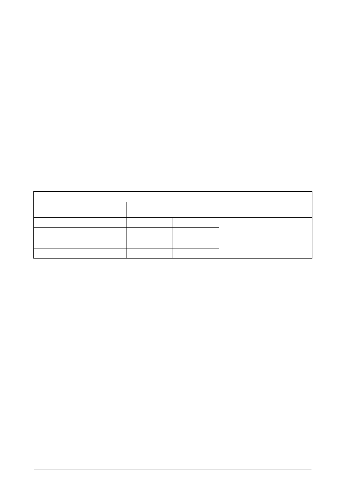
Portable X-ray Units power requirements are:
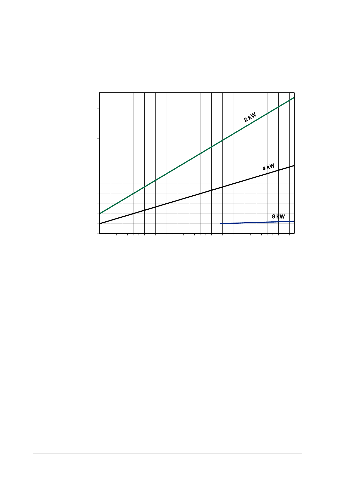
Maximum Power kW 2.0 4.0 8.0
Single-Phase, 100 -- 240 VAC, 50 / 60 Hz. Single-Phase,
220 -- 240 VAC, 50 / 60 Hz.
Power Line Operation Line voltage automatic compensation: ±10%
Power line cable of the Portable Unit: 6 meters.
Connection to standard outlets with GND that accomplishes local regulations.
Maximum Power Line Impedance Refer to Illustration 1-1
The General Circuit Breaker installed in the Portable Unit is 32 A (curve type C)
with a 30 mA Sensitivity Differential.
The Power Line Installation should be provided with a 30 mA Sensitivity Differential
and with a Thermomagnetic Interruptor / Circuit Breaker of at least:
Minimum recommended
Thermomagnetic / Circuit Breaker
²16 A (curve type C) or
²10 A (curve type D)
for 100 -- 120 VAC
²8 A (curve type C) or
²6 A (curve type D)
for 220 -- 240 VAC
²30 A (curve type C) or
²16 A (curve type D)
for 100 -- 120 VAC
²16 A (curve type C) or
²10 A (curve type D)
for 220 -- 240 VAC
²30 A (curve type C) or
²16 A (curve type D)
for 220 -- 240 VAC
Momentary Line Current based on 100 ms X-ray exposure (RMS)
Note .
Portable X-ray Units
Service Manual
SM-1076R2
2
Illustration 1-1
Maximum Power Line Impedance
0.0
0.2
0.4
0.6
0.8
1.0
1.2
1.4
1.6
1.8
2.0
2.2
2.4
2.6
2.8
90 100 110 120 130 140 150 160 170 180 190 200 210 220 230 240 250 260
LINE VOLTAGE (VRMS)
MAXIMUM POWER LINE IMPEDANCE (OHMS)
1.2 TOOLS AND TEST EQUIPMENT
The following test equipment is required in Configuration, Calibration and
Troubleshooting and Maintenance:
•Standard service engineers tool kit.
•Oscilloscope.
•Non-invasive kVp Meter.
•Digital Multimeter.
•Calculator.

Portable X-ray Units
Service Manual
SM-1076R2 3
SECTION 2 CONFIGURATION PROCEDURE
Configuration and Calibration procedures should only be
performed at field if Portable Control Board, Control Driver
Board or the High Voltage Transformer are replaced or the
EEPROM memory is re-initialized.
All procedures described in this Service Manuals are
performed from the Control Panel of the X-ray Unit.
Configuration provides the initial settings and checkout procedures that must
be carried out before starting to work with the Unit. Functional characteristics
of this Generator are defined during Configuration.
Calibration data and some configuration data are stored in the extended
memory area of the non-volatile memory U25-EEPROM Microcontroller. It is
located on the Portable Control Board (A3175--03).
Do not supply the main power until specifically instructed in
this document.
2.1 CONFIGURATION OF DIP SWITCHES
The Dip Switches located in the Portable Control Board (A3175-03) define the
Unit configuration:
DipSwitchSW1 Description
1* ON = Service mode enabled
OFF= Service mode disabled
2ON = Hardware errors disabled
OFF= Hardware errors enabled
3ON = Demo mode enabled
OFF= Demo mode disabled
4ON = Filaments disabled
OFF= Filaments enabled
* NOTE.-- Access to Service mode can be also performed using the keyboard as indicated in
Section 2.2 while dipswitch is in “OFF” position.
All Dip Switches are Factory set to OFF position for normal operation.

Portable X-ray Units
Service Manual
SM-1076R2
4
2.2 HOW TO ENTER AND STORE DATA IN CONFIGURATION MODE
Configuration data is entered from the Control Panel when the Unit is in Service
Mode. Access and configure data as indicated below:
1. Turn the Unit ON and immediately press and hold “Reset” push-button
to enter in Service Mode. The Unit starts its power-up routine and the
software version (a.e. P01 0103) is shown on the Display of the Control
Panel.
= Vers. 1, Rev. 01.03
kVp mAs
2. When the letters “CAL” appear in the kVp Display, release “Reset”
push-button.
kVp
3. Then the Displays show the selected power percentage (a.e. Po = 100)
followed by the standard kVp and mAs values.
Unit power = 100%
kVp mAs
The Unit is equipped with eight (8) Configuration groups (C01 to C08)
and their subgroups are shown on the kVp Display when they are
selected. (Refer to Table 2-1 “Configuration Menus”).
4. To enter or exit the Configuration menu:
a. Press and hold “Collimator Light” push-button and then press and
release “kVp Increase” push-button (two beeps sound). (Con)
appears on the kVp Display while “Collimator Light” is pressed,
then release “Collimator Light” (kVp Display shows C01 and both
Focal Spot Leds blink).
1
2
Press and hold Collimator Light
Press and release kVp Increase
Release Collimator Light
3
kVp

Portable X-ray Units
Service Manual
SM-1076R2 5
b. Press “kVp Increase” or “kVp Decrease” push-buttons to move
through Configuration menus to select any of them (the kVp
Display shows menus from C01 to C08).
c. Press “Collimator Light” push-button to enter in the sub-menus.
d. Press “kVp Increase” or “kVp Decrease” to scroll through
sub-menus of each menu and select any of them.The desired
selection will be shown on the kVp Display.
e. Press “Collimator Light” push-button to exit the sub-menus.
f. To exit Configuration Mode, press and hold “Collimator Light”
push-button and then press and release “kVp Increase”
push-button (two beeps sound). Then release the “Collimator
Light” push-button.

Portable X-ray Units
Service Manual
SM-1076R2
6
Table 2-1
Configuration Menus
Value on kVp Display DESCRIPTION NOTES
WORKSTATION-1 CONFIGURATION
C1.1 X-ray Tube present
0 = WS not used, 1 = Tube 1
C01 C1.2
Workstation Type:
0 = Direct, 1 = Bucky / Detector,
2 = not used
Values factory set.
Original values must not be modified.
Refer to Section 2.2.1
C1.3 Device selection:
0 = none, 1 = Bucky / Detector input
C1.4 0 = not used
WORKSTATION-2 CONFIGURATION
C2.1 X-ray Tube present
0 = WS not used, 1= Tube 1
C02
C2.2
Workstation Type:
0 = Direct, 1 = Bucky / Detector,
2 = not used
Values factory set.
Original values must not be modified.
Refer to Section 2.2.1
C2.3 Device selection:
0 = none, 1 = Bucky / Detector input
C2.4 0 = not used
mA STATION CONFIGURATION FOR EACH FOCUS Refer to Section 2.2.2
C03
C3.1
mA Stations for “Small Focal Spot”:
5.000 mA - 100.0 mA
(for 2 kW unit mA Station are limited)
Set Maximum mA station for “Small Focal Spot”
C3.2
mA Stations for “Large Focal Spot”:
5.000 mA - 100.0 mA
(for 2 kW unit mA Station are limited)
Set Minimum mA Station for “Large Focal Spot”
X-RAY TUBE LIST SELECTION / number of Tube in the list
C
4
1
X-ra
y
Tube Con
f
i
g
uration as Tube--1:
C04 C4.1
X
-
r
a
y
T
u
b
e
C
o
n
f
i
g
u
r
a
t
i
o
n
a
s
T
u
b
e
--
1
:
1-9 Refer to Section 2.2.3
C4.2 X-ray Tube Configuration as Tube--2:
not used

Portable X-ray Units
Service Manual
SM-1076R2 7
Table 2-1 (cont.)
Configuration Menus
Value on kVp Display DESCRIPTION NOTES
TIME CONFIGURATION FOR “PREP” AND COLLIMATOR LIGHT Refer to Section 2.2.4
C05 C5.1 “Prep” Time Configuration:
10 - 50 seconds Factory Configured at 30 seconds.
C5.2 “Collimator Light” Time Configuration:
10 - 50 seconds Factory Configured at 30 seconds.
MAXIMUM X-RAY TUBE POWER Refer to Section 2.2.5
C06
C6.1 Maximum percentage limit for X-Ray Tube Select the maximum power percentage
at 100, 90, 80 or 70.
MISCELLANEOUS Refer to Section 2.2.6
C7.1 Speaker Sound: OFF / ON OFF: all sounds disabled except for Exp.
ON: all sounds enabled (factory set).
C07 C7.2 Winter / Summer Automatic Time Update:
NO / YES
NO: automatic time update disabled.
YES: automatic time update enabled
(factory set).
C7.3 Collimator Light ON with PREP: OFF / ON
OFF: Collimator Light only enable with button
(factory set).
ON: Collimator Light enable when pressing
“PREP”.
DATE AND TIME Factory set at GMT +1.Refer to Section 2.2.7
C8.1 Hour 0-23
C
0
8
C8.2 Minutes 0-59
C08
C8.3 Date 1-31
C8.4 Month 1-12
C8.5 Year 2000 - 2099
If any of the configurated values is not consistent with the Unit
Parameters, the system will not allow to exit from Configuration
mode. Double check the configured values (Refer to Table 2-1).
Note .
Portable X-ray Units
Service Manual
SM-1076R2
8
2.2.1 CONFIGURATION OF WORKSTATIONS (1) -- (2)
To select Workstation 1 press the “Direct” Workstation push-button, to select
Workstation 2 press the “Receptor” (Bucky or Digital Detector) Workstation
push-button.
In case the Receptor Workstation for the Digital Detector or Bucky
is selected and no Digital Detector or Bucky is connected to the
Unit or the connection is malfunctioning, error code “E24” appears
on the Display. Press “Reset” push-button and check connections
and signals of the Digital Detector or Bucky, or select the
Workstation for Direct if no Receptor is needed.
Factory Setting
Workstation 1
Direct
Workstation 2
Bucky or Detector
Workstation 1 or 2
if not Bucky or Detector
C1.1 1C2.1 1
C1.2 0C2.2 1
S
e
t
a
l
l
v
a
l
u
e
s
0
C1.3 0C2.3 1
Set all values 0
C1.4 0C2.4 0
In case a Workstation configuration needs to be modified:
1. Enter Configuration Menu C01 (for Workstation-1) or C02 (for
Workstation-2).
2. Enter sub-menu C1.X or C2.X, the kVp Display shows (C1.X) or (C2.X)
and the mAs Display shows the selectable values.
As example, enter sub-menu C1.1 or C2.1. The kVp Display shows
(C1.1) or (C2.1) and the mAs Display shows (0) or (1). “X-ray Tube
present” value is “0” for Workstation not used or “1” for X-ray Tube--1
present (Workstation used).
3. Press “mAs Increase” to change the corresponding value from a.e. “0”
(Workstation not used) to “1” (Tube present -- Workstation used) or
viceversa.
4. Press “Reset” push-button to save value.
Note .

Portable X-ray Units
Service Manual
SM-1076R2 9
2.2.2 CONFIGURATION OF mA STATIONS FOR EACH FOCUS
1. Enter Configuration menu C03.
2. Enter sub-menu C3.1. The kVp Display shows (C3.1) and the mAs
Display shows (Factory set 20.00).
3. To change the corresponding maximum value of mA station for Small
Focus, press “mAs Increase” or “mAs Decrease”. Factory default value
is 20 mA.
4. Press “Reset” push-button to save value.
5. Press “kVp Increase”, the kVp Display shows sub-menu (C3.2) and mAs
Display shows (Factory set 5.000).
6. To change the corresponding minimum value of mA station for Large
Focus, press “mAs Increase” or “mAs Decrease”. Factory default value
is 5 mA.
7. Press “Reset” push-button to save value.
8. Press “Collimator Light” push-button to exit the sub-menus.The kVp
Display shows (C03).
Maximum mA station recommended for the ”Small Focus” is 20.0.
The minimum mA station for “Large Focus” should be the lowest
mA station allowed by the Unit. For 2 kW unit mA Station are
limited.
Note .

Portable X-ray Units
Service Manual
SM-1076R2
10
2.2.3 X-RAY TUBE SELECTION
1. Select Configuration menu C04.
2. Enter sub-menu C4.1 (for Tube-1) or C4.2 (for Tube-2). The kVp Display
shows (C4.1 or C4.2) and mAs Display shows the Tube identifier.
3. To change the X-ray Tube ID (identifier, shown on the kVp Display for
seconds) press “mAs Increase / Decrease” and set the ID shown on the
“Inspection Report” document of the Unit.
4. Press “Reset” push-button to save data. The Tube ID is momentarily
shown on the kVp Display and a beep sounds.
5. Press “Collimator Light” push-button to exit the sub-menus.The kVp
Display shows (C04).
Errors E07 or E08 appear when the Tube ID is a default value
(E07 for Tube 2 and E08 for Tube 1).
In case the HV Transformer has been replaced, request the
manufacturer the Tube identifier to be configured.
2.2.4 TIME CONFIGURATION FOR “PREP” AND COLLIMATOR LIGHT
1. Select configuration menu C05.
2. Enter sub-menu C5.1 for “Prep” Time Configuration. The kVp Display
shows (C5.1) and the mAs Display shows (Factory set at 30 seconds,
within this lapse of time “Exp” button should be pressed, otherwise the
exposure will not be allowed).
3. Press “mAs Increase” or “mAs Decrease” to change Preparation Time.
Value Factory set at 30 (range from 10 to 50).
4. Press “Reset” push-button to save value.
5. Press “kVp Increase” to enter sub-menu C5.2 for Collimator Light Time.
The kVp Display shows (C5.2) and mAs shows (Factory set 30).
6. Press “mAs Increase” or “mAs Decrease” to change Collimator Light
Time.Value Factory set at 30 seconds (range from 10 to 50).
7. Press “Reset” push-button to save value.
8. Press “Collimator Light” push-button to exit sub-menus. The kVp Display
shows (C05).
This manual suits for next models
6
Table of contents
Other Sedecal Medical Equipment manuals


