Seedburo Count-A-Pak 801 Service manual

10” Shallow Bowl
Seedburo
Model 801
COUNT-A-PAK Seed Counter
Operating and service Manual
7” Bowl
10” Standard Bowl
SEEDBURO EQUIPMENT CO.
2293 South Mount Prospect Rd.
Des Pl ines, IL 60018
(312) 738-3700
MANUAL REVISION 6.0
MAN0016
07/12/2012

1
TA LE OF CONTENTS
1. INTRODUCTION.................................................................................... P ge 4
2. FUNCTIONAL DESCRIPTION............................................................... P ge 4
3. INSTALLATION AND SETUP................................................................ P ge 5
3.1 Unp cking.........................................................................................P ge 5
3.2 Connection....................................................................................... P ge 7
4. OPERATING PROCEDURE.................................................................. P ge 9
4.1 Power-up......................................................................................... P ge 9
4.2 Est blishing Oper ting P r meters................................................. P ge 9
4.3 Selecting An Oper ting Mode.......................................................... P ge 10
4.3.1 TOTAL Mode.......................................................................... P ge 11
4.3.2 SINGLE BATCH Mode........................................................... P ge 12
4.3.3 BATCH REPEAT Mode.......................................................... P ge 12
4.3.4 MULTIPLE BATCH Mode...................................................... P ge 13
4.4 St rting the Counting Process........................................................ P ge 14
4.5 Stopping the Counting Process....................................................... P ge 14
4.6 Oper ting Hints................................................................................ P ge 15
5. DISPLAYS AND CONTROLS.............................................................. P ge 16
6. PROMPTS AND MESSAGES............................................................... P ge 18
6.1 Scrolling Mess ges.......................................................................... P ge 18
6.2 St tion ry Mess ges....................................................................... P ge 20
7. ADJUSTMENTS AND MAINTENANCE................................................. P ge 21
7.1 Setting the G te Time....................................................................... P ge 21
7.2 Seed Tone Oper tion........................................................................ P ge 21
7.3 Ch nging the Required Oper ting Volt ge of OCC.......................... P ge 22
7.4 Feeder Bowl Alignment..................................................................... P ge 23
7.5 Adjusting Bowl Devices..................................................................... P ge 23
7.6 Checking nd Ch nging Vibr tory Feeder Springs........................... P ge 24
7.7 Sp re P rts nd Accessories List......................................................P ge 27
8. TROUBLESHOOTING GUIDE............................................................. P ge 28
8.1 Vibr tory Feeder............................................................................... P ge 28
8.2 Diverter Assembly............................................................................. P ge 28
8.2.1 Electric l Problems.................................................................. P ge 28
8.2.2 Mech nic l Problems.............................................................. P ge 28
8.3 Oper tor Control Console................................................................. P ge 29
9. WARRANTY.......................................................................................... P ge 30
10. SPECIFICATIONS................................................................................ P ge 31

2
APPENDIX
A. SERIAL COMMUNICATIONS.............................................................. P ge 32
A.1 801 Initi ted output............................................................................ P ge 32
A.1.1 Function................................................................................... P ge 32
A.1.2 End of Run D t Tr nsmission............................................... P ge 32
A.1.2.1 TOTAL mode............................................................. P ge 32
A.1.2.2 SINGLE BATCH mode.............................................. P ge 32
A.1.2.3 BATCH REPEAT mode............................................. P ge 32
A.1.2.4 MULTIPLE BATCH mode.......................................... P ge 32
A.3 Ch r cter Legends............................................................................. P ge 33
A.4 Line Settings...................................................................................... P ge 33
A.4.1 B ud R te............................................................................... P ge 33
A.4.2 D t Bits nd P rity................................................................. P ge 33
A.5 Seri l Port Connector......................................................................... P ge 33
A. INDEX .............................................................. P ge 34/35
A. Troubleshooting Guide .............................................................. P ge 36/37
A. P cking instructions .............................................................. P ge 38/39

3
TA LE OF FIGURES
Figure 3-1 M jor Components................................................... P ge 5
Figure 3-2 Bowl Quick Rele se Assembly................................ P ge 6
Figure 3-3 Connections.............................................................. P ge 7
Figure 5-1 Displ ys nd Controls.............................................. P ge 16
Figure 7-1 Power Input Connector............................................ P ge 22
Figure 7-2 Volt ge Selector C rd Orient tion.......................... P ge 22
Figure 7-3 P rts nd lignment to Diverter Chute Assembly... P ge 23
Figure 7-5 Side view of feeder Spring St cks........................... P ge 25
Figure 7-6 Model EB-00 Vibr tory Feeder............................... P ge 25
Figure 7-7 Adjusting Feeder Air G p........................................ P ge 26
Figure 8-1 Diverter Assembly................................................... P ge 29

4
1. INTRODUCTION
Congr tul tions! You h ve chosen the most technologic lly dv nced seed counter v il ble tod y. The
Seedburo Model 801 Count-A-P k incorpor tes st te-of-the- rt CMOS microprocessor technology nd full front
p nel progr mm bility to provide you, the user, with the ultim te in flexibility nd reli bility.
M jor fe tures include:
° Membr ne Touch P nel
° Functions for Tot lizing, B tching, Repe t B tch, nd Multiple B tching
° Modul r Design - Oper tor Control Console sep r te from Seed H ndling B se
° Two Versions of Seed H ndling B se with either 7" or 10" Feeder Bowl
° Bowl Conversion - Interch nge ble Seed H ndling B se with s me Oper tor Control
Console
° Rugged St inless Steel Design
° Seri l D t Interf ce (RS232)
° Optic l Seed Sensing Device
° B g / No B g Detection Circuitry
° Option l St rt/Stop foot Switch
° Quick Disconnect for Feeder Bowl
° C n Be Shipped by UPS
° New LED optic ssembly cre tes less he t, t kes less power, nd provides for more
ccur te counts
2.
FUNCTIONAL DESCRIPTION
The 801 Count-A-P k seed counter is n electronic device speci lly designed to count wide r nge of seeds.
Du l microprocessor b sed circuitry is employed to ssure reli ble oper tion. Count-A-P ks re fully tested before
shipment nd re re dy to oper te upon delivery. Some djustment of control devices is needed for different seed
sizes.
Seeds re pl ced in the feeder bowl. The bowl h s spir lly inclined tr ck round the inside perimeter. Seeds
re moved upw rd long this tr ck by electrom gnetic vibr tion. R te of seed movement is djusted by use of the
SPEED control setting. Adjust ble devices utom tic lly rr nge seeds to form single file line, one l yer deep.
Seeds re disch rged into n output chute nd detected by n opto-electronic sensor. Sensitivity (or Threshold) of
the sensor c n be djusted to count v rious seed sizes.
ACCURACY is function of counting speed. The gre test ccur cy is chieved by controlled, single-file
delivery. Seeds th t form single file e sily m y be counted f ster th n others. Counting SPEED is limited by
how e sily seeds form single file nd how ccur te the counting must be. Some ch ffy seeds count best t high
speed ... the r pid motion tends to unt ngle them. When very high speed is needed, some ccur cy m y be lost.
F st, ccur te counting c n be expected from dry, cle n seeds of rel tively uniform size th t form single file
e sily.

5
. INSTALLATION AND SETUP
3.1 Unpacking
C refully remove the OPERATOR CONTROL CONSOLE (OCC), SEED HANDLING BASE (SHB), nd BOWL of
the COUNT-A-PAK from p ck ging cont iners (see Figure 3-1). Pl ce OCC nd SHB units on solid, level
surf ce. M ke sure the locking h ndle of the BOWL is pointing forw rd to the unlocked position (see Figure 3-2).
Lower bowl over slotted sh ft on SHB. Adjust cle r nce between diverter output chute nd bowl disch rge re to
pproxim tely 1/16 inch (this m y h ve to be slightly less on some very sm ll seeds, see (Figure 7-3, item 9) for
bowl lignment). Push lock h ndle upright to fully vertic l position to secure bowl.
CAUTION!!!!! DIVERTER
CHUTE ASSEMBLY IS
FRAGILE. DO NOT USE IT AS
A HANDLE TO LIFT THE SHB.
Bowl
Oper tor Control Console (OCC)
Figure 3-1 M jor Components
Seed H ndling B se (SHB)

6
INSTALLATION HINTS:
*Keep origin l p ck ging cont iners for stor ge or future shipping purposes. Diverter chute ssembly must be
protected during stor ge or shipment with c reful p ck ging.
*The feeder bowl is p ck ged sep r tely. It is m de of c st luminum nd m y cr ck or bre k if dropped. A
cr cked or d m ged bowl must be repl ced. The SHB nd feeder bowl h ve smooth udible hum when
running.
Do not restrict bowl vibration in any manner. If an unusual striking noise or sharp knocking occur at any
time during operation, turn Feeder OFF immediately! Serious damage may occur if not corrected
promptly. See Section 7.4 if sharp
knocking occurs.
Locked Position
1. Feeder Bowl
2. Handle
. 10- 2 Locknuts
4. Spring
5. U-Bracket
6. Bowl Nuts
7. 10- 2 Nuts
8. Shaft
9. Sleeve
10. Key
Unlocked Position
Figure -2 Bowl Quick release Assembly
7
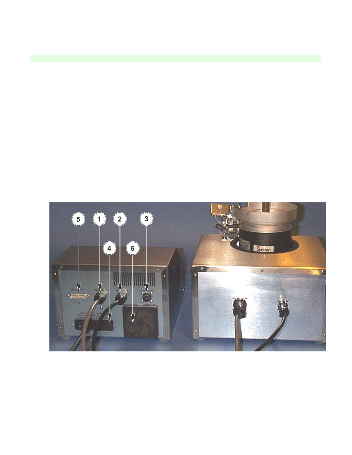
3.2 Connection
Connect the c bles from OCC (P17 Figure 3-3 #1, SHB CONTROL nd P18 Figure 3-3 #2, SHB POWER) to the
m ting connectors on the re r of the SHB. The SHB CONTROL c ble connects to the 28 pin connector on the
SHB (left side of re r p nel, looking from re r of unit). The SHB POWER c ble connects to the 8 pin connector on
the SHB (right side of re r p nel, looking from the re r of unit). If the option l foot-switch h s been ordered,
connect it to P19 (Figure 3-3 #3) on the OCC.
Verify th t the volt ge required is ppropri te for your power line volt ge. The required volt ge c n be determined
by ex mining the power input connector ssembly (P5 Figure 3-3 #4) on the re r of the OCC. Count-A-P ks re
designed for 115V or 230V oper tion, lthough they will oper te over r nge of 100-130V or 200-260V. There
re 4 sm ll holes on the right-h nd end of this connector ssembly, which re l beled 100V, 120V, 220V, nd
240V. There will be sm ll white indic tor pin in one of these holes (see Figure 7-1). The volt ge indic ted
beside th t m rker is the line volt ge for which the OCC is configured. The Count-A-P ks re typic lly shipped
with this set to 120V or 240V position. The 100V nd 220V positions re used only for very low line volt ges.
Addition lly, ll units which require 200V to 260V will be l beled "220 VOLTS" on both the OCC nd the line cord
(for further inform tion see Section 7.3).
Figure - Connections

8
Although the OCC c n be configured for wide r nge of volt ges nd frequencies, the SHB c nnot. The volt ge
nd frequency required for the SHB m y be determined from the seri l number t g on the re r p nel of the SHB.
It will work only on the volt ge nd frequency m rked.
* * * * * * *
ELECTRICAL EQUIPMENT MUST E PROPERLY GROUNDED FOR SAFETY OF
OPERATING PERSONNEL. DO NOT OPERATE UNIT FROM A RECEPTACLE
WHICH LACKS A PROPER 3 WIRE TYPE GROUNDING CONNECTION.
* * * * * * *
All Count-A-P ks re equipped with three wire power cord. When connected to proper power recept cle, the
entire unit is grounded. Due to the wide v ri tion of power line connectors used throughout the world, ll units for
other th n 120 volt oper tion must h ve the proper loc l power line connector tt ched to the line cord prior to
oper tion. The color coding of the line cord wires is s follows:
Light Blue - Neutr l
Brown - Hot
Green/Yellow - E rth Ground
CAUTION: Be sure th t the proper power plug is tt ched prior to powering up the 801. F ilure to do so m y
c use d m ge nd void your w rr nty.
Be sure the power switch on the left-h nd end of P5(Figure 3-3 #4) is turned off before connecting line cord to P5
nd power line outlet.

9
4. OPERATING PROCEDURE
4.1 Power-Up
Turn on the power switch on the re r p nel of the OCC. The diverter g te will switch positions sever l
times to check the solenoids. All LEDs nd LED displ y segments will light for sever l seconds llowing
visu l check for b d LEDs. The mess ge displ y will show the mess ge "REVISION X.X" (X.X is current
softw re revision) for few seconds, followed by the mess ge "CALIBRATING" while the unit performs n
intern l c libr tion of the sensitivity level. (Ensure there is nothing in the chute to interrupt the light be m
during c libr tion).
The mess ge displ y will next indic te "SELECT MODE" nd the SPEED, SENSITIVITY, nd COUNT
displ ys will show the most recently used v lues. the STOP switch LED will be illumin ted while the
MULTIPLE BATCH, BATCH REPEAT, SINGLE BATCH nd TOTAL switch LEDs will be fl shing.
A "Beep" tone will be he rd when v lid switch is pressed. A lower tone indic tes n inv lid switch
selection. The mplitude of this tone m y be djusted with very sm ll fl t bl de screwdriver vi 1/4
inch hole on right h nd side of the bottom of the OCC c binet.
4.2 Establishing Operating Parameters
The first time the unit is used, or if the unit h s been left unpowered for more th n 3 months, the oper ting
p r meters should be progr mmed. This is ccomplished by pressing the MENU switch t this time. The
mess ge displ y will indic te "CHK SETTNGS?". Press the ENTER/YES switch. The mess ge displ y
will indic te "BAG DET. ON?". Press ENTER/YES to en ble the b g detection circuit or CLEAR/NO to
inhibit oper tion of the b g detection circuits.
The mess ge will now be "GATE DLY (ms)". The number fl shing in the COUNT displ y is the del y in
milliseconds between the time seed is detected by the opto-electronic sensor nd the time the diverter
g te switches chutes. This is used only in the v rious B tch modes of oper tion to ensure th t counted
seed h s time to get p st the g te into the proper b g before the g te switches to the other b g. This
setting will typic lly be in the 30-50 ms r nge nd m y be determined empiric lly s expl ined in Section
7.1. A new number m y be entered from the keybo rd, followed by ENTER/YES. A r nge of 0 to 99 ms
is v lid. The current setting c n be selected by pressing ENTER/YES.
The mess ge displ y next shows "SD.TONE ON?". If ENTER/YES is pressed, short beeping tone will
be he rd e ch time seed is counted. A CLEAR/NO response will inhibit this tone. The function of this
tone is expl ined in Section 7.2.
The next mess ge displ yed is "AUTO PRT ON?". If ENTER/YES is selected, d t will be tr nsmitted to
the seri l port on the re r of the 801 t the end of e ch run, or e ch time STOP is pressed. If the seri l
communic tions port is not being used or if Autoprint is not desired, press CLEAR/NO. This function is
expl ined more fully in Appendix A.

10
The fin l mess ge, "9600=Y1200=N", refers to the seri l d t tr nsmission r te, or b ud r te, det iled in
Appendix A. This option is only import nt if some type of equipment, such s printer or computer/d t
logger is connected to the seri l port on the b ck of the 801. Choose ENTER/YES to select 9600 b ud, or
CLEAR/NO to select 1200 b ud. If the seri l port is not being used, either of these c n be chosen, s
they will h ve no effect. Refer to Appendix A for more inform tion.
The mess ge displ y reverts b ck to "SELECT MODE".
4.3 Selecting An Operating Mode
An oper ting mode must now be selected. There re 4 oper ting modes which m y be selected. The
four modes re:
TOTAL - Counts the tot l number of seeds in given lot through one chute. The feeder
st ys on until stopped or pprox. 2 minutes fter the l st seed is counted. See Section 4.3.1 for
det il.
SINGLE BATCH - A single qu ntity of seeds counted from l rger bulk mount. The termin l count
(number of seeds in b tch) is preset in the COUNT displ y prior to counting. The 801 counts
this number of seeds into one chute nd then stops the feeder, ch nges the diverter g te
position, nd relo ds the termin l count. In order to count nother b tch, it is necess ry to
press the st rt switch g in. For inst nce, if it is desired to count ex ctly 38 seeds into b g,
the COUNT displ y is set to 38 before st rting the feeder. When 38 seeds h ve been counted
into the b g, the diverter g te will switch to prevent ny more seeds from f lling into th t chute
nd the feeder will stop. See Section 4.3.2 for more det il. Another B tch m y be counted by
ch nging the b g or putting b g on the other chute t this time nd pressing START g in.
BATCH REPEAT - Counts single qu ntity of seeds from l rger bulk mount into one chute, then
ch nges the diverter g te to the other chute, relo ds the termin l count, nd counts nother
b tch into th t chute. This ction continues, ltern ting chutes, nd requires the oper tor to
ch nge b gs e ch time one is filled (i.e., If BAG DETECT ON nd h s been selected, the
counting will termin te if previously filled b g is not removed before the diverter g te
switches b ck to th t chute). The counting will termin te if b g is not present on the delivery
chute nd BAG DETECT ON h s been selected. The mess ge displ y indic tes the number
of b tches counted. See Section 4.3.3 for more det il.
MULTIPLE BATCH - Up to 99 Groups of up to 99 B tches e ch m y be selected. E ch Group must be
defined in terms of termin l count (number of seeds in e ch B tch) nd number of B tches.
The 801 will oper te simil r to BATCH REPEAT mode, but will stop t the end of e ch Group,
nd prompt the oper tor to check b g size for the next Group. The counting will lso termin te
if b g is not present on the delivery chute nd BAG DETECT ON h s been selected.

11
As n ex mple, ssume it is desired to count 20 B tches of 38 seeds e ch nd then 10 B tches of 15
seeds e ch. Group 01 will be set for Count of 38 nd B tches t 20. Group 02 will be set for Count of
15 nd B tches t 10. See Section 4.3.4 for more det il.
Select the desired oper ting mode by pressing one of the four Mode switches nd verify or modify the
p r meters th t re displ yed.
4.3.1 TOTAL Mode
Press the TOTAL switch to select this mode ny time the feeder is not running. The mess ge displ y will
indic te "SPEED OK?" nd the SPEED displ y will fl sh the current speed setting. This m y be djusted
up or down with the rrows under the SPEED displ y, followed by ENTER/YES. It m y lso be ch nged
by entering numeric v lue between 00 nd 99 followed by ENTER/YES.
Next the mess ge displ y will indic te "SENS. OK?" nd the SENSITIVITY displ y will fl sh the current
sensitivity v lue. The SENSITIVITY is djusted in simil r m nner utilizing the rrows under the
SENSITIVITY displ y.
Upon pressing ENTER/YES to confirm the sensitivity v lue, the mess ge displ y will indic te "COUNT
OK?" nd the COUNT displ y will fl sh the current count. This will norm lly be reset to zero (0) in this
mode by pressing CLEAR/NO (mess ge displ y will indic te "MODIFY NOW!!") followed by ENTER/YES.
It c n lso be set to ny numeric v lue, nd will proceed to count up from th t v lue. If it is desired to
enter such v lue, it is ccomplished by pressing CLEAR/NO nd entering the v lue on the numeric
keyp d followed by ENTER/YES.
The BATCH nd GROUP displ ys h ve no function in this mode.
After pl cing the seeds to be counted in the bowl, the feeder is st rted by pressing START or the extern l
foot-switch. If the b g detector is on, b g must be present in order to st rt the feeder. The feeder st ys
on until the bowl becomes empty (no seeds counted for pproxim tely 3 minutes) or is m nu lly stopped
by the STOP switch or option l foot-switch. It will lso stop if the b g detector is on nd the b g is
removed during counting.
4.3.2 SINGLE ATCH Mode
Press the SINGLE BATCH switch to select this mode ny time the feeder is not running. The mess ge
displ y will indic te "SPEED OK?" nd the SPEED displ y will fl sh the current speed setting. This m y
be djusted up or down with the rrows under the SPEED displ y followed by ENTER/YES, or by entering
numeric v lue between 00 nd 99 followed by ENTER/YES. The speed m y lso be djusted during
counting with the up or down rrows.
Next the mess ge displ y will indic te "SENS. OK? nd the SENSITIVITY displ y.will fl sh the current
sensitivity v lue. The SENSITIVITY is djusted in simil r m nner utilizing the rrows under the
SENSITIVITY displ y.

12
Upon pressing ENTER/YES to confirm the sensitivity v lue, the mess ge displ y will indic te "COUNT
OK?" nd the COUNT displ y will fl sh the current termin l count. It should be set to the number of seeds
desired in the b tch, nd will proceed to count down to zero (0) from th t v lue. Entering new termin l
count is ccomplished by pressing CLEAR/NO nd entering the v lue on the numeric keyp d followed by
ENTER/YES.
The BATCH nd GROUP displ ys h ve no function in this mode.
After pl cing the seeds to be counted in the bowl, the feeder is st rted by pressing START or the extern l
foot-switch. If the b g detector is on, b g must be present on one of the chutes in order to st rt the
feeder (It doesn't m tter which chute the b g is on, s the 801 will utom tic lly select the one with
b g). The feeder st ys on until the b tch is counted, t which point the feeder stops nd the mess ge
"FINISHED" is displ yed. The feeder m y lso be m nu lly stopped by pressing the STOP switch or
option l foot-switch. The feeder will lso stop if the b g detector is on nd the b g is removed during
counting.
4.3.3 ATCH REPEAT Mode
Press the BATCH REPEAT switch to select this mode ny time the feeder is not running. The mess ge
displ y will indic te "SPEED OK?" nd the SPEED displ y will fl sh the current speed setting. This m y
be djusted up or down with the rrows under the SPEED displ y, followed by ENTER/YES. It m y lso
be ch nged by entering numeric v lue between 00 nd 99 followed by ENTER/YES.
Next the mess ge displ y will indic te "SENS. OK?" nd the SENSITIVITY displ y will fl sh the current
sensitivity v lue. The SENSITIVITY is djusted in simil r m nner utilizing the rrows under the
SENSITIVITY displ y.
Upon pressing ENTER/YES to confirm the sensitivity v lue, the mess ge displ y will indic te "COUNT
OK?" nd the COUNT displ y will fl sh the current termin l count. It should be set to the number of seeds
desired in e ch b tch, nd will proceed to count down to zero (0) from th t v lue. Entering new termin l
count is ccomplished by pressing CLEAR/NO nd entering the v lue on the numeric keyp d followed by
ENTER/YES.
The BATCH nd GROUP displ ys h ve no function in this mode.
After pl cing the seeds to be counted in the bowl, the feeder is st rted by pressing START or the extern l
foot-switch. If the b g detector is turned on, t le st one b g must be present in order for the feeder to
st rt, but norm lly two b gs will be present in this mode. The 801 will not deliver seeds into n empty
chute with the b g detector on.
Seeds re counted into one chute until the count re ches zero, the diverter g te then switches to the other
chute, the termin l count is relo ded, nd counting continues into the other chute. The MESSAGE
DISPLAY will indic te the number of BATCHES th t h ve been counted. If the b g detector is turned off,
this ction will continue indefinitely, ltern ting delivery chutes, s long s there re seeds in the bowl. If,
however, the b g detector is turned on, filled b g on either chute must be ch nged before seeds will
g in be delivered into th t chute. Otherwise, the feeder will stop nd the mess ge displ y will indic te
"CHECK BAG".

13
The b g should be ch nged nd the counting will continue upon pressing the START switch. This fe ture
prevents double filling b g.
If the b gs re ch nged fter e ch b tch, the feeder st ys on until the bowl is empty, t which point the
feeder stops nd the mess ge "BOWL EMPTY" is displ yed. If this should occur, the number of b tches
counted c n be rec lled by pressing the ENTER/YES switch.
The feeder m y lso be m nu lly stopped by pressing the STOP switch or option l foot-switch.
4.3.4 MULTIPLE ATCH Mode
Press the MULTIPLE BATCH switch to select this mode ny time the feeder is not running. The mess ge
displ y will indic te "SPEED OK?" nd the SPEED displ y will fl sh the current speed setting. This m y
be djusted up or down with the rrows under the SPEED displ y, followed by ENTER/YES. It m y lso
be ch nged by entering numeric v lue between 00 nd 99 followed by ENTER/YES.
Next the mess ge displ y will indic te "SENS. OK?" nd the SENSITIVITY displ y will fl sh the current
sensitivity v lue. The SENSITIVITY is djusted in simil r m nner utilizing the rrows under the
SENSITIVITY displ y.
Upon pressing ENTER/YES to confirm the sensitivity v lue, the mess ge displ y will indic te "GROUP
OK?". The BATCH nd GROUP displ ys re used only in this mode. The GROUP displ y will show the
current Group, the COUNT displ y will show the termin l count for the displ yed GROUP, nd the BATCH
displ y will show the number of b tches in the displ yed Group. If both the COUNT nd BATCH numbers
re correct, this Group should be confirmed with ENTER/YES. If either of these numbers re wrong,
pressing CLEAR/NO will llow modific tion of COUNT nd then BATCH. Entering new termin l count is
ccomplished by pressing CLEAR/NO nd entering the v lue on the numeric keyp d followed by
ENTER/YES. A new number m y then be entered for BATCH followed by ENTER/YES.
Addition l Groups re entered in simil r m nner. Up to 99 Groups m y be entered, nd e ch Group
m y cont in up to 99 B tches.
After pl cing the seeds to be counted in the bowl, the feeder is st rted by pressing START or the extern l
foot-switch. If the b g detector is turned on, t le st one b g must be present in order for the feeder to
st rt, but norm lly two b gs will be present in this mode. The 801 will not deliver seeds into n empty
chute with the b g detector on, but will stop the feeder nd indic te "CHECK BAG". The feeder m y be
rest rted s bove t this point, fter checking the b g.
Seeds re counted in b tches s in BATCH REPEAT mode until the number of B tches in Group re
completed. At this point, the feeder will stop nd the displ y will prompt the oper tor to "CHECK BAG
SIZE--PRESS START TO RESUME... NEXT GROUP--". The next Group is then counted simil rly, nd
this ction continues until ll Groups re complete, t which time "FINISHED" will ppe r on the mess ge
displ y. If the b g detector is turned off, the Group will count to completion, ltern ting chutes for e ch
B tch in the Group reg rdless of whether the b gs re ch nged, or even present.

14
If, however, the b g detector is turned on, filled b g on either chute must be ch nged before seeds will
g in be delivered into th t chute. The feeder m y lso be m nu lly stopped by pressing the STOP
switch or option l foot-switch.
4.4 Starting the Counting Process
Pl ce the seeds to be counted into the bowl. Be sure b g(s) re in position on the chute(s). Press
START (or press the option l foot-switch, which is remote st rt/stop switch). The vibr tory feeder will be
ctiv ted nd the LED on the START switch will light nd the LED on the STOP switch will go out. As the
seeds begin to f ll through the chute, the count will be shown on the COUNT DISPLAY. The SPEED nd
SENSITIVITY settings m y be djusted while the unit is oper ting by using the UP/DOWN rrows under
the respective displ ys.
4.5 Stopping the Counting Process
The vibr tory feeder m y be stopped t ny time by pressing the STOP switch (or option l foot-switch). In
the TOTAL nd BATCH REPEAT modes, the Count-A-P k will lso stop fter f ilure to count seed for
sever l minutes. If this occurs, the mess ge displ y will show "BOWL EMPTY", indic tive of n empty
bowl. In the SINGLE BATCH or MULTIPLE BATCH modes, the Count-A-P k will lso stop fter re ching
the termin l count or completing ll Groups, respectively. The mess ge displ y will show "FINISHED"
when this occurs.
At this point, the unit m y be rest rted or nother oper ting mode selected.
4.6 Operating Hints
For most counting oper tions, extremely precise djustments nd c libr tions re not necess ry. Close
ttention to det il is required when counting very sm ll seeds, or seeds mixed with debris. Ch nging light
conditions fter st rting count c n ffect ccur cy. This pplies to overhe d lighting, nd ny other light
source th t is directed t the 801. Inc ndescent l mps should not be llowed to shine directly into the
chute. Fluorescent lights should h ve little effect, unless flickering.
To become f mili r with the settings, use sm ll s mple of seeds nd run TOTAL count sever l times
nd verify the results. (A control s mple is c refully counted s mple of seeds.) Select different Speed
nd Sensitivity settings while checking the ccur cy of the counts. A control s mple is useful for checking
ccur cy t regul r interv ls
1. Problems with new equipment often occur from f ilure to underst nd instructions. Become f mili r
with the troubleshooting guide to prevent unnecess ry del ys in the use of your COUNT-A-PAK.
2. Problems with new equipment often occur from f ilure to underst nd instructions. Become f mili r
with the troubleshooting guide to prevent unnecess ry del ys in the use of your COUNT-A-PAK.
3. Keep unit cle n. Cle n ir filter on re r p nel of OCC Figure 3.3 #6 t le st every 90 d ys, more
often under extremely dusty conditions. Filter m y be ch nged without tools by c refully removing
sn p-off cover nd w shing filter medi in so p nd w ter. Repl ce medi nd cover. Do not oil ny
p rts t ny time. Alw ys keep feeder bowl nd gl ss cover pl tes on diverter chutes cle n. A sm ll
soft bristle brush is recommended. Do not use high pressure ir, s mech nic l d m ge to the
diverter ssembly could result. The gl ss cover pl tes m y be removed nd w shed in so p nd
w ter, if desired.

15
4. When counting into b gs or envelopes, chutes m y become blocked. Alw ys le ve enough cle r nce
between bottom of chute nd bottom of cont iner for seeds. If block ge occurs, cle r from bottom
of chutes only, otherwise d m ge to diverter fl p m y result.
5. Reset counter displ ys before counting begins. Cle n s mples count most ccur tely.
6. NEVER use chutes s h ndles to move the instrument.
7. Service nd rep irs re most e sily done by qu lified rep irm n. If help is needed, time nd trouble
c n be s ved by c lling the m nuf cturer for service ssist nce.
Cont ct Inform tion
SALES: Seedburo Equipment Co. SERVICE: AgPoint Precision LLC
2293 South Mount Prospect Rd. 24121 West Theodore Street
Des Pl ines, IL 60018 Pl infield, IL 60586
(312) 738-3700 FAX: (312) 738-5329 (866)668-4855 FAX: (312) 878-6400

16
5. DISPLAYS AND CONTROLS
There re five numeric displ ys, one mess ge displ y, six indic tor LEDs (Light Emitting Diodes), nd
twenty-three key-switches on the OCC. There is lso power on/off switch loc ted on the re r of the
OCC on the power entry module. The function of e ch displ y nd control follows.
(1) Count Displ y ................................... Displ ys number of seeds counted in TOTAL
mode nd number of seeds rem ining in current B tch in
Figure 5-1 Displ ys nd Controls

17
(2) Mess ge Displ y .............................. Displ ys v rious mess ges nd oper tor prompts.
(3) BATCH Displ y ................................. Displ ys the number of B tches in Group in MULTIPLE BATCH mode.
This is ctive only in the BATCH REPEAT mode.
(4) GROUP Displ y ................................ Displ ys the number of the current Group in MULTIPLE BATCH
oper tion. This is ctive only in the BATCH REPEAT mode.
(5) SENSITIVITY Displ y ....................... Displ ys the current Sensitivity setting. M ximum sensitivity (for sm ll
seeds) is 00 nd minimum sensitivity (for l rge seeds) is 99.
(6) SPEED Displ y ................................. Displ ys the current Speed (Amplitude) setting for the vibr tory feeder.
Minimum speed is 00 nd m ximum speed is 99.
(7) MODE Switches ............................... These four key-switches re used to select the oper ting mode when the
SELECT MODE prompt is present.
(8) MENU Switch ................................... Press this switch followed by ENTER/YES to configure def ult settings or
press this switch followed by CLEAR/NO to return to mode selection ny
time feeder is off.
(9) Numeric Keyswitches ....................... Used to enter numeric v lues for (0-9) v rious p r meters. The entered
v lue must be followed by ENTER/YES.
(10) ENTER/YES Switch ......................... Termin tes numeric entries nd design tes n ffirm tive response to
question prompts.
(11) CLEAR/NO Switch........................... Cle rs existing p r meter v lues nd design tes neg tive response to
question prompts.
(12/13) Sensitivity ....Up/Down Arrows....Incre ses (13) or Decre ses (12) Sensitivity of detector. Lower number is
more sensitive.
(14/15) Speed Up/Down Arrows ............. Incre ses (14) or Decre ses (15) vibr tory feeder mplitude. L rger
number is higher speed.
(16) START/RESTART Switch ............... St rts count cycle nd the vibr tory feeder. Altern tely, START c n be
initi ted vi the option l foot-switch.
(17) STOP Switch ................................... Stops vibr tory feeder or interrupts count cycle. Altern tely, stop
controlled by option l foot-switch.
(18) Mode Indic tors ............................... Red LED illumin tes to indic te the selected mode of oper tion: TOTAL,
SINGLE BATCH, BATCH REPEAT, or MULTIPLE BATCH.(19) Feeder
On Indic tor Illumin tes to indic te vibr tory feeder is running.
(20) Feeder Off Indic tor ........................ Illumin tes to indic te vibr tory feeder is not running.

18
6. PROMPTS AND MESSAGES
6.1 Scrolling Messages
There re sever l mess ges th t scroll continuously cross the mess ge displ y until the oper tor intervenes.
These re:
"PRESS ENTER TO RECORD..."
Pressing the ENTER/YES key stores the currently displ yed p r meter v lue in ret ined memory.
"USE LAST PROGRAM? (YES OR NO)..."
Pressing ENTER/YES uses previous progr m, while CLEAR/NO llows new progr m to be entered.
"PRESS START, CLEAR, MODE, OR MENU..."
Pressing START will initi te the counting process. CLEAR will delete the current p r meter. Pressing one
of the four mode switches will select th t mode of oper tion. MENU will return to the st rtup menu.
"ANOTHER GROUP? (YES OR NO)..."
ENTER/YES will llow entry of p r meters for n ddition l Group. CLEAR/NO will signify th t this is the
l st Group.
"NEXT GROUP--CHECK AG SIZE--PRESS START TO RESUME..."
This indic tes th t Group h s been completed nd sign ls the oper tor to verify th t the proper b g size
is in pl ce for the next Group. Pressing START will initi te counting of the next Group.
6.2 Stationary Messages
There re sever l st tion ry mess ges. These re:
"SELECT MODE" One of the four oper ting modes must be selected.
"SPEED OK?" Verify current Speed setting with ENTER/YES, or ch nge setting utilizing one of sever l
methods. The setting c n be ch nged using the up/down rrows. It c n lso be ch nged
by entering new v lue vi the numeric keyp d followed ENTER/YES. Also, if CLEAR/NO
is pressed, the mess ge "MODIFY NOW!!" will ppe r nd new v lue c n be entered vi
the numeric keyp d followed by ENTER/YES. Note: The Speed c n be djusted during
counting vi the up/down rrows.

19
"SENS. OK?" Verify current Sensitivity setting with ENTER/YES, or ch nge setting utilizing one of sever l
methods. The setting c n be ch nged using the
up/down rrows. It c n lso be ch nged entering new v lue vi the numeric keyp d
followed by ENTER/YES. Also, if CLEAR/NO is pressed, the mess ge "MODIFY NOW!!"
will ppe r nd new v lue c n be entered vi the numeric keyp d followed by
ENTER/YES. Note: The Sensitivity c n be djusted during counting vi the up/down
rrows.
"OWL EMPTY" This mess ge ppe rs when seed h s not been counted in sever l minutes. This is the
norm l termin tion in TOTAL nd BATCH REPEAT modes.
"NO AG" This indic tes th t b g must be tt ched to one of the chutes, using the b g ret iner clip,
prior to st rting, or b g w s removed during cycle. This function m y be dis bled vi
the "CHK SETTNGS" function in the m in menu.
"FINISHED" This mess ge ppe rs when the counting is complete in SINGLE BATCH or MULTIPLE
BATCH modes.
"COUNT OK?" Verify current Count setting with ENTER/YES, or ch nge setting utilizing one of sever l
methods. It c n be ch nged by entering new v lue vi the numeric keyp d followed by
ENTER/YES. Also, if CLEAR/NO is pressed, the mess ge "MODIFY NOW!!" will ppe r
nd new v lue c n be entered vi the numeric keyp d followed by ENTER/YES.
"ATCHES OK?" Verify the current number of b tches in this Group with ENTER/YES, or ch nge setting
utilizing one of sever l methods. It c n be ch nged by entering new v lue vi the numeric
keyp d followed by ENTER/YES. Also, if CLEAR/NO is pressed, the mess ge "MODIFY
NOW!!" will ppe r nd new v lue c n be entered vi the numeric keyp d followed by
ENTER/YES.
"GROUP OK?" Verify the current settings of Termin l Count nd B tches in this Group with ENTER/YES,
or ch nge settings by pressing CLEAR/NO.
"MODIFY NOW!!" Enter new v lue for the current p r meter vi the numeric keyp d followed by
ENTER/YES.
"PRESS START" Press START to initi te counting.
"PRESS STOP" Press STOP to interrupt the counting.
"CHK SETTNGS?" Press ENTER/YES to modify the current def ult settings of b g detector oper tion, line
frequency, g te del y, nd seed tone oper tion. Press CLEAR/NO to return to the
"SELECT MODE" function.
"REVISION X.X" This is displ yed immedi tely fter power-up prior to c libr tion. The number which
ppe rs in pl ce of X.X is the softw re revision number which should be provided to obt in
support.
"AG DET. ON?" Pressing ENTER/YES en bles the B g Detect circuit. CLEAR/NO inhibits its oper tion.
This manual suits for next models
10
Table of contents


