Oval EL0122 User manual

Ins. No. E-122-8-E
Every OVAL product is manufactured under stringent quality control and thoroughly tested and inspected
before shipment from our factory. To expect the stated performance throughout its service life, please
familiarize yourself with the instructions contained in this manual before use.
Also keep it for ready reference. It is suggested that the instruction manuals for the companion pulse
generator (flowmeter) and receiving instrument be referred to at the same time.
TOTAL COUNTER
MODEL EL012 2
3

E-122-8-E
1. BEFORE YOU BEGIN............................................................................................................................. 4
1.1 Confirming the Tag ............................................................................................................................ 4
1.2 Transportation Considerations .......................................................................................................... 4
1.3 Storage Considerations..................................................................................................................... 4
2. GENERAL ............................................................................................................................................... 5
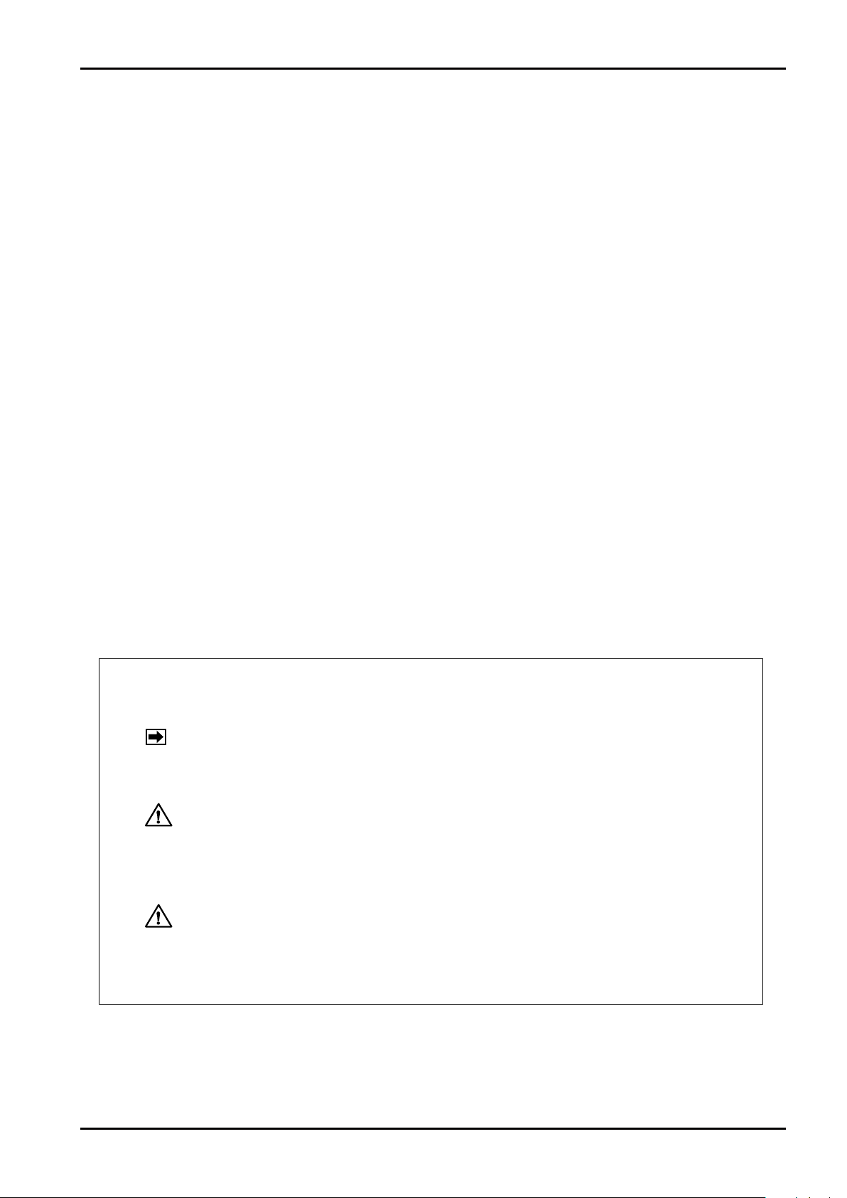
3. PART NAMES AND OUTLINE DIMENSIONS ....................................................................................... 5
4. INSTALLATION....................................................................................................................................... 5
4.1 Installation Location .......................................................................................................................... 5
4.2 Installation ......................................................................................................................................... 5
5. WIRING ................................................................................................................................................... 6
5.1 Cables for Field Wiring...................................................................................................................... 6
5.2 Field Wiring and Electrical Connections............................................................................................ 6
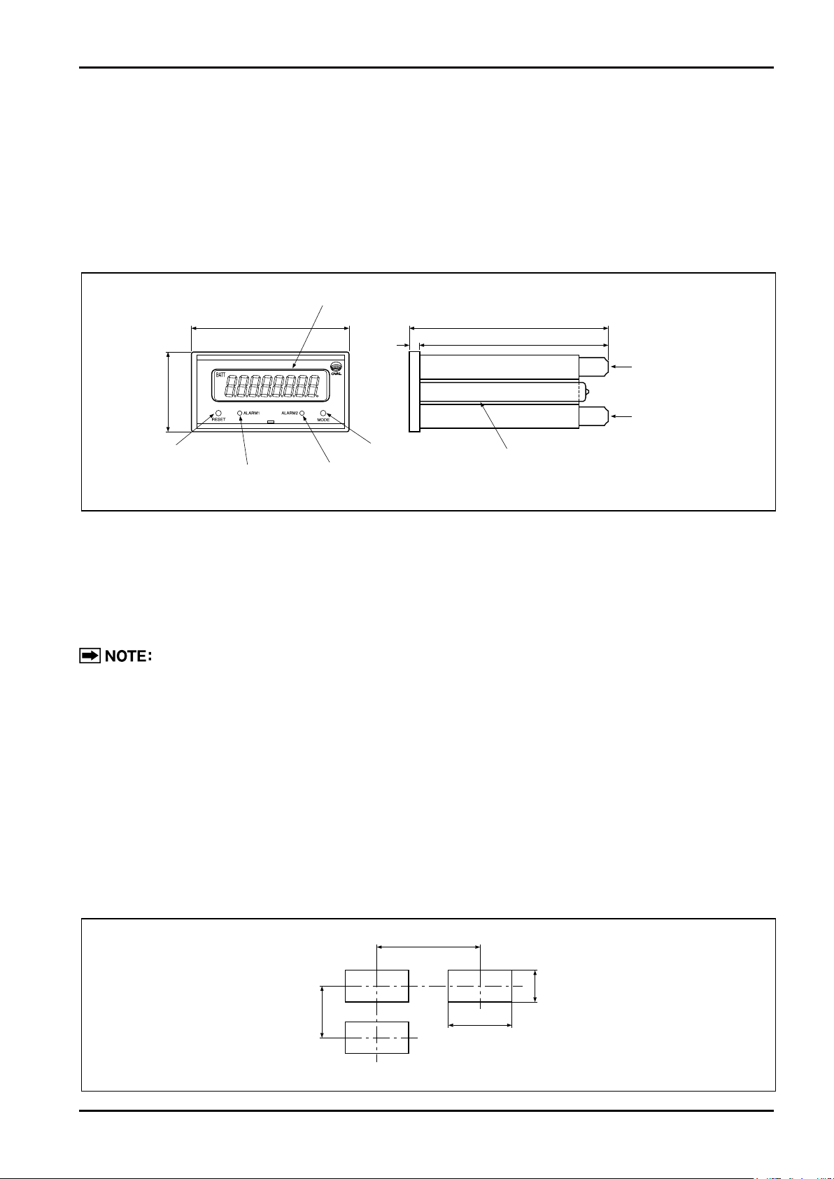
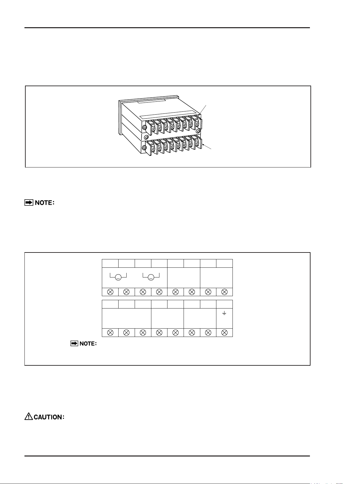
5.3 Terminal Block for External Connections .......................................................................................... 6
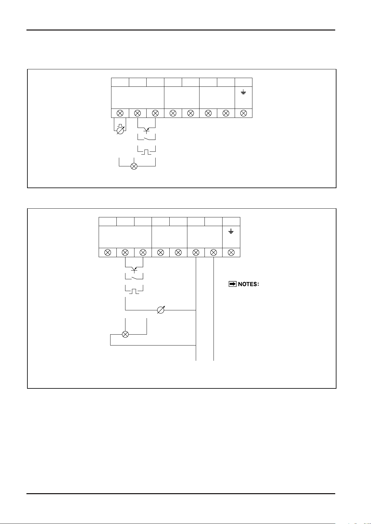
5.4 Electrical Connections by Type of Input Signal ................................................................................. 8
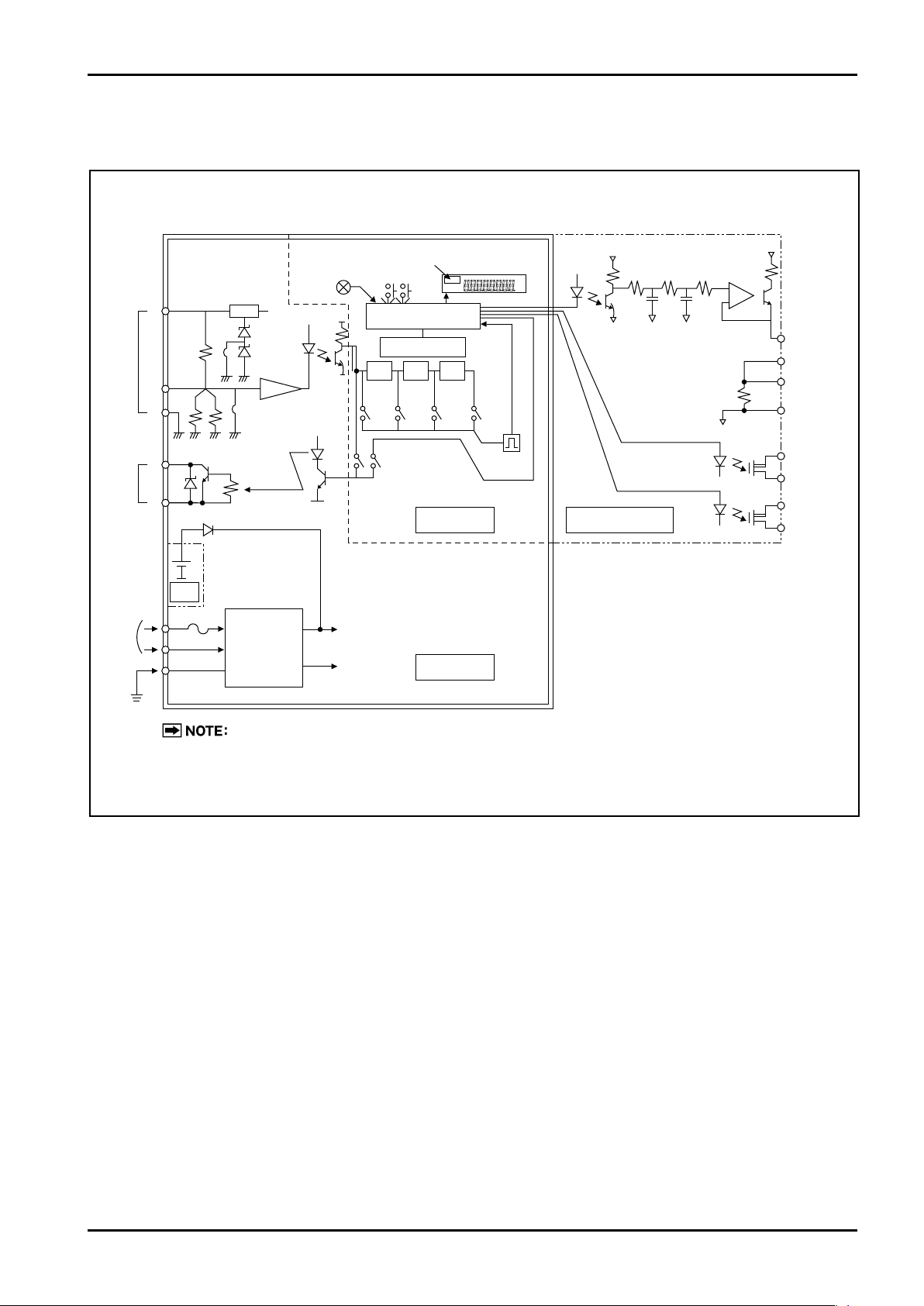
6. BLOCK DIAGRAM.................................................................................................................................. 9
7. FUNCTIONS AND OPERATION .......................................................................................................... 10
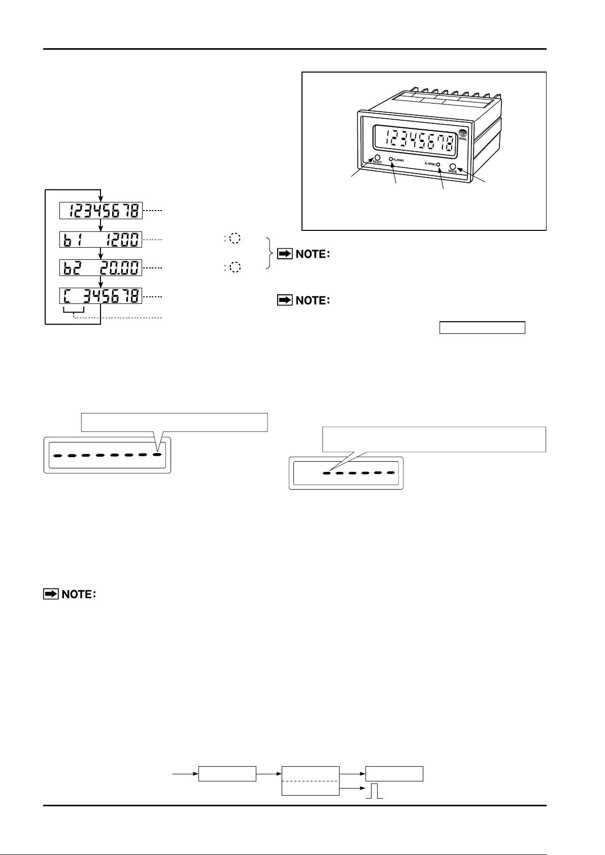
7.1 LCD Counter Display ...................................................................................................................... 10
7.2 About the Displayed Messages during Operation ........................................................................... 10
7.3 Computing Formula for Total Flow and Instantaneous Flowrates ................................................... 10
7.4 Jumper, Switch, Potentiometer Setup and Adjustment ....................................................................11
7.4.1 Construction of Internal Electronics Assembly ...........................................................................11
7.4.2 How to Remove Internal Electronics Assembly..........................................................................11
7.4.3 Waveshaping Function .............................................................................................................. 12
7.4.4
Setup of Other Functions (common to EL0122/0123) LCD Board SW3
......................................... 13
7.4.5 How to Change Output Signal and Pulse Width (option) .......................................................... 13
7.4.6
Parameter Setup, Alteration, and Adjustment in Analog Output Circuit (option)........................ 13
7.5 Parameter Setup Procedure ........................................................................................................... 14
7.5.1 Procedure to Modify a Parameter ............................................................................................. 14
7.5.2 Procedure to Enter a Parameter ............................................................................................... 14
7.5.3 About Dummy Output Features (special functions)................................................................... 16
7.5.4 Parameter Initialization.............................................................................................................. 16
7.5.5 About Alarm Output (option) ...................................................................................................... 17
7.5.6 About Error Messages............................................................................................................... 18
●Table 7.5 Menu Trees and Switch Operation................................................................................... 20
●Table 7.6 Parameter List.................................................................................................................. 20
8. BATTERY REPLACEMENT.................................................................................................................. 22
8.1 About the Batteries.......................................................................................................................... 22
8.2 Battery Replacement....................................................................................................................... 22
CONTENTS

E-122-8-E
9. OPERATION ....................................................................................................................................... 23
9.1 Preparation Before Operation ....................................................................................................... 23
9.2 Operation....................................................................................................................................... 23
10. TROUBLESHOOTING ........................................................................................................................ 23
11. GENERAL SPECIFICATIONS ............................................................................................................ 24
12. PRODUCT CODE EXPLANATION..................................................................................................... 25
12.1 EL0122 ........................................................................................................................................ 25
12.2 EL0123 ........................................................................................................................................ 26
13. FORMER PRODUCT CODE EXPLANATION .................................................................................... 27
13.1 EL0122 ........................................................................................................................................ 27
13.2 EL0123 ........................................................................................................................................ 27
The indications NOTE, CAUTION, and WARNING shown throughout this
manual are to draw your attention to specific items:
NOTE:
Notes are separated from the general text to bring user's attention to
important information.
CAUTION:
Caution statements call attention to user about hazards or
unsafe practices that could result in minor personal injury or
property damage. .
WARNING:
Warning statements call attention to user about hazards or
unsafe practices that could result in serious personal injury or
death.

E-122-8-E
1. BEFORE YOU BEGIN
When you received, the product should be thoroughly inspected for any sign of damage by rough
handling during transit.
1.1 Confirming the Tag
Product code and ratings appear on the counter tag. Make sure that the product you received complies
with the specifications in your order.
General Specifications and Product Code Explanation appear on pages 24 and 25, respectively.
When you inquire, supply complete information as to the product name, model number,
product number, ratings, etc.
1.2 Transportation Considerations
(1) The OVAL total counter can best be transported to the installation site in the shipping container
used for transit from our factory.
(2) Avoid giving impact shocks to the total counter during transit.
1.3 Storage Considerations
If the total counter upon receipt is to be stored for extended periods of time before installation, unexpected
problems could arise. If such is the case, the following considerations should be taken:
(1) The total counter can best be stored in the original package used for transit from the factory.
(2) Select a storage location that meets the following requirements:
☆ Free from rainwater and moisture
☆ Least vibration and impact shock
☆ In the room temperature and humidity environment (around 25℃ and 65% R.H.)
A total counter which has been idle for extended periods of time may possibly require internal
inspection. If such is the case, consult factory.
Tag (nameplate) shows ratings.
Fig.1.1 Tag Location

2. GENERAL
Built around a single-chip microprocessor, this multifunction counter is designed lightweight and compact.
It offers four display functions (cumulative total flow, hourly and per-minute instantaneous flowrate, and
resettable total flow) in a single unit along with a factored pulse output.
A 4-20mA DC and 1-5V DC flowrate output plus high/low alarm output are available as an option (Model
EL0122 only).
3. PART NAMES AND OUTLINE DIMENSIONS
4. INSTALLATION
4.1 Installation Location
(1) Select a location free from mechanical vibration and corrosive gases.
(2) Select a location maintained at room temperature with least temperature variation and free from
moisture.
We guarantee that the counter is operational at ambient temperatures from -10 to +50℃,
but we recommend an installation location where the temperature is controlled to the room
temperature.
(3) Provide a sufficient working space behind the counter to facilitate electrical connections and
maintenance.
4.2 Installation
(1) This counter is designed for panel mount.
(2) Mount the counter as follows:
① Remove panel-mount fittings from the counter and front mount the counter through the opening
cut in the panel.
② Secure the counter to the panel with panel-mount fittings from inside the panel, slightly forcing
them outwardly at first.
E-122-8-E
8-digit LCD display
Dimensions in millimeters
Analog/alarm output
terminal block
(option)
(M3.58P)
Terminal block
for ext. conn.
(M3.58p)
96 110
105.5
6.5
48
"ALARM1" LED "ALARM2" LED
"MODE" button
"RESET" button Panel mount fitting
Fig.3.1
Dimensions in millimeters
120 min.
92+0.8
0
45+0.6
0
70 min.
Fig.4.1 Panel Cut

E-122-8-E
5. WIRING
5.1 Cables for Field Wiring
Use electrostatically-shielded, polyethylene-insulated, vinyl-sheathed control cables (CEVS 0.75 to 2mm2,
2- or 3-conductor), or equivalent, for input and output signal cables.
5.3 Terminal Block for External Connections
Before connecting the cables, ensure that the flowmeter (pulse generator) is compatible with this counter.
Acceptable combinations of these units can be determined by identifying their model number and
instrument number.
Invalid equipment combination can lead to a costly downtime. Be sure to reconfirm validity
following wiring connections.
5.2 Field Wiring and Electrical Connections
(1) It is recommended that cables be routed through conduits.
Be sure to route the power cable separate from the input and output signal cables.
(2) Keep the cables away from other power cables or power circuits if any, to prevent stray current pickup.
If inductive interference is suspected, use a capacitor or surge suppressor where necessary.
(3) Use crimp-style terminals to ensure good electrical connections. Terminals for connections are located
on the back of this instrument.
Fig.5.2 Extermal Conn. Terminal Blocks
1
A
+
-
+
-
2345678
V
+
-
ANALOG OUT
ALARM1 OUT ALARM2 OUT
12345678
L1(+) ( )L2(
-
)
FLOW INPUT PULSE OUT POWER
SUP SIG. 0V
The upper terminal block at back of the counter is provided only in
models with analog/alarm output.
Terminal block
(Installed in models with analog/alarm output)
Terminal block
Fig.5.1

E-122-8-E
Name Terminals Description
Power
6
L1
7
L2
85-264V AC, 50/60Hz
(Model EL0122 only)
(+) (−)
or 12−24V DC±10% (Model EL0123 only)
Ground (8) To be earth grounded
Pulse
Input
Contact-closure
or open collector
PG20 Flowpet - 5G,
(N)PG60A(E3)
1, 2, 3 EL0122 1: 12V DC 2: SIG.
(+) 3: 0V
(−)
2, 3 EL0123 2: SIG. (+) 3: 0V
(−)
Voltage pulse PG30
(N)PG60A(F)
1, 2, 3 EL0122 1: 12V DC 2: SIG.
3: 0V
2, 3 EL0123 2: SIG. 3: 0V
Current pulse
PA14, 15, 25
(N)PG60A(E),
PG30S
1, 2 EL0122 1: + (+24 or 12V DC) 2: −
2 EL0123 2: − Load 510Ω(*)
Pulse
Output Open collector 4, 5 4:+
5:− (Isolated only in Model EL0122)
Analog
Output
4-20mA DC 1, 2 1:+
2:−
Optional feature (Model EL0122 only)
If ①and ②are not used, do not fail to
short them out. Unless so shorted out,
no analog voltage output appears across
terminals 3 and 4.
1-5V DC 3, 4 3:+
4:−
Alarm
Output
Alarm 1 5, 6 Output signal: Non-contact relay ×2 points
Capacity: 230V AC/340V DC, 200mA
"ON" resistance: 16Ωmax. (Leak current 1μA min. at
"OFF")
Alarm 2 7, 8
◎Terminal Block Identification for External Connections
1. Power cannot be supplied to the transmitters of certain flowmeters, such as the
Thermistor Type Vortex Flowmeter, DC Power Type Coriolis Flowmeter, etc.
Prepare a power source separately, or relay it using another device.
2. An asterisk (*) indicates requirement for a separate power source.

E-122-8-E
5.4 Electrical Connections by Type of Input Signal
(1) Model EL0122
(2) Model EL0123
Fig.5.4
+
+
-
+
-
-
1 2 3 4 5 6 7 8
L1(+)
(+) (
-
)
L2(
-
)
FLOW INPUT
12V
24V or 12V
12V
0V
SIG.(GENERATOR)
PULSE OUT POWER
SUP. SIG. 0V
OPEN COLLECTOR PULSE
CURRENT PULSE
CONTACT-CLOSURE PULSE
2-WIRE SYSTEM
VOLTAGE PULSE
3-WIRE SYSTEM
OPEN COLLECTOR PULSE
3-WIRE SYSTEM
VOLTAGE PULSE
POWER TO PULSE GENERATOR
12V DC TO 24V DC
1. FOR CURRENT PULSE OR 3-WIRE
SYSTEM PULSE INPUT, AN ADDI-
TIONAL POWER SUPPLY FOR
PULSE GENERATOR IS REQUIRED.
2. POWER SUPPLY TO PULSE GEN-
ERATOR MAY BE COUPLED TO
POWER TERMINALS TO PROLONG
BATTERY LIFE.
3. POWERISNOTSUPPLIEDBY
EL0123.
Fig.5.3
+
+
-
-
12345678
L1(+)L2(
-
)
FLOW INPUT
12V 0V
SIG.
(GENERATOR)
PULSE OUT POWER
SUP. SIG. 0V
OPEN COLLECTOR PULSECURRENT PULSE
CONTACT-CLOSURE PULSE
2-WIRE SYSTEM VOLTAGE PULSE
3-WIRE SYSTEM OPEN COLLECTOR PULSE
3-WIRE SYSTEM VOLTAGE PULSE

E-122-8-E
6. BLOCK DIAGRAM
(1) Model EL0122
(2) Model EL0123
In the Model EL0122 overall block diagram above, the following circuits are eliminated:
①Regulated voltage supply (transformer) circuit and power circuit to the pulse generator because it
operates on the battery.
②Isolation circuit and F/I board (option).
Pulse inPulse out
1
2
3
4
5
6
7
8
POWER
GND
Power to
generator
J5
J1
1
J2
2 3
12V
12V
BATT
Stabilized
voltag
supply
(trans.)
1A
Voltage
detect RESET MODE
BATT LCD COUNTER
CPU
LCD board F/l board (option)
E2PROM
1/2 1/5 1/10
SW3-4
1/1
SW3-5
1/2
SW3-6
1/10
SW3-7
1/100
SW3-8
Factored (std.)
SW3-10
Unfactored
Power board
250Ω
Analog
output
Alarm
output
Alarm 1
Alarm 2
①+
4〜20mA
1〜5V
②−
③+
④−
④
⑤
⑥
⑦
Battery (option) for EL0122 serves to light the LCD when power is off.
Fig.6.1

E-122-8-E
10
7. FUNCTIONS AND OPERATION
The counter is designed to show the following
variables on the display using "MODE" and "RESET"
pushbuttons.
7.1 LCD Counter Display
Upon each depression of "MODE" button, the LCD
display scrolls through available variables as shown
Only incoming pulses having small periodic
variation produce meaningful readins.
(See section 7.3.)
RESET button is operative only in this mode.
The counter resets to zero upon "RESET"
button depression.
7.2 About the Displayed Messages during Operation
(1) Ordinary operation
"MODE" switch is turned "ON"
⇒8 bars appear.
⇒Immediately turning "OFF" scrolls the window
to the next one. ⇒Holding turned ON until the last bar disappears results
in "prolonged depression" processing (Turning OFF
before the last bar disappears results in the same
behavior as in ①to take place.)
※ Prolonged operation: An operation required for Normal
mode ⇔Parameter review mode selection, finalizing
the parameter setting, etc.
Indicates a countdown before "prolonged depression"
processing takes place.
(2) Prolonged operation
"MODE" switch is held turned ON without turning
"OFF" immediately by removing the fingers.
⇒Bars begin to disappear from the leftmost one.
7.3 Total Flow and Instantaneous Flowrate Calculation and About Factored Pulse Output
(1) Total flow
Each time a single pulse (after frequency division by hardware means) arrives at the CPU, "Parameter
F×Parameter H" is added up to the current reading of total flow.
●The LCD shows a reading down to the decimal places set at "Parameter SP" menu.
●When the reading has reached its maximum reading (99999999), the reading returns to zero.
(2) Factored pulse output
Produces a pulse output to read in the unit set at "Parameter Pu" menu.
"ALARM2"
LED
"ALARM1"
LED
"MODE" button
Fig.7.1
"RESET" button
When the RESET switch is pressed in a mode where the RESET switch is valid, the display
behaves the same as described above. (There is no distinction between ordinary operation and
prolonged operation, however.)
Accumulated total flow
Display
Instant.
flowrate /h
/min
Instant.
flowrate
Resettable total flow
Mode code
Indicates that the switch is turned "ON."
Freq. division
Hardware
1/1 or 1/10 or 1/100
Incoming pulses
CPU
(F×H)
Pu
LCD display
Factored pulse output
C 0

E-122-8-E
11
(3) Instantaneous flowrate
When the CPU accepts count (Parameter A) of pulses sampled within sampling time (Parameter At )
[sec], its period or the interval of occurrence T [sec] is measured. The instantaneous flowrate is then
determined by the following equations:
Hourly flowrate b1=3600×F×H×A/T
Per-mimute flowrate b2= 60×F×H×A/T
1.b1 shows a reading down to the decimal places set at "Parameter bP" menu.
2.b2 shows a reading down to the decimal places of b1 + 2 addditional places.
3.In the absence of any incoming pulses within sampling time At [sec], the instantaneous
flowrate reads "0".
4.If the instantaneous flowrate exceeds 99999, the reading remains at "99999".
7.4 Jumper, Switch, Potentiometer Setup and Adjustment
◎The counter is configured to customer specifications at the factory and no further adjustment
is required except for later changes or adjustment.
Alteration and adjustment above requires removal of internal electronics.
7.4.1 Construction of Internal Electronics Assembly
In the pulse type, the internal assembly consists of a display board and a power supply board. The
analog type (option) has three boards with an additional F/I board. The power supply board and F/I board
connect to the display board. At the back, a terminal block for external connections is found. See "How to
Remove Internal Electronics Assembly" outlined on the next page.
7.4.2 How to Remove Internal Electronics Assembly
Do not fail to turn off power before removal.
Remove wiring connections with this assembly.
①Remove panel mounting fitting and
draw the assembly out from the
panel rear panel opening.
②Taking off rear panel fitting screws,
remove the rear panel.
③Extract the internal electronics
assembly to the rear.
Panel Mounting Fitting Rear Panel
Internal Electronics Assembly
Fig.7.5Fig.7.4Fig.7.3
Fig.7.2
F/I Baord (option)
Display Board
Power Supply Board
Terminal Blocks

E-122-8-E
1
7.4.3 Waveshaping Functions
(1) EL0122 (power supply board)
Table 7.1 Pulse Input Types and Input Setup Specifications
Pulse input type OVAL pulse generator
model
Jumper settings Power to
generator
Input
impedance
J2 J5 J1
Contact-closure PG20
1-C Shorted *113.5VDC 5 kΩ
Open collector (N) PG60A(E3),
Flowpet-EG
Voltage pulse PG30, (N) PG60A (F) 2-C Shorted *113.5VDC 22 kΩ
Current pulse
PA14, 15, 25
(N) PG60A (E) 3-C Open *124 VDC 510 Ω
PG30S 3-C Shorted *113.5VDC 510 Ω
(2) EL0123 (power supply board)
Table 7.2 Pulse Input Types and Input Setup Specifications
Pulse input type OVAL pulse generator
model
Jumper settings Input impedance
J2 J1
Contact-closure
or open collector PG20 1-C *120 kΩ
Voltage pulse PG30, (N) PG60A (F) 2-C *1100 kΩ
Current pulse
PA14, 15, 25
(N) PG60A (E) 3-C *1510 Ω
PG30S 3-C *1510 Ω
*1: Short out if it is desired to increase the waveshaping filtering by tenfold approx.
◆Install a jumper in the shadowed sockets on the power supply board shown below according to
your particular specifications.
Jumper settings in selecting the pulse input spec.: J2
(2)
J2
EL0122
(1) (3)
(2)
J2
EL0123
(1) (3)
(2)
J2
EL0122
(1) (3)
(2)
J2
EL0123
(1) (3)
(2)
J2
EL0122
(1) (3)
(2)
J2
EL0123
(1) (3)
Fig.7.7 EL0123 Power Supply Board
J2
J2
Fig.7.6 EL0122 Power Supply Board
①1-C
②2-C
③3-C

E-122-8-E
1
SW3 Auxiliary Functions
1 ON:Write-protect OFF: Rewritable
2ON→OFF resets accumulated total flow.
Normally OFF
3 No functions. (Always OFF)
SW3 Hardware frequency division settings
1/1 1/2 1/10 1/100
4 ON OFF OFF OFF
5 OFF ON OFF OFF
6 OFF OFF ON OFF
7 OFF OFF OFF ON
SW3
Output pulse settings
Factored Unfactored
(sync with input)
8 ON OFF
9 OFF OFF
10 OFF ON
7.4.4 Configuration of other Functions (common to EL0122/0123): LCD board SW3
7.4.5 How to Change Output Signal and Pulse Width
Output pulse width of this counter is set to a default of 1ms., and if the customer's option is 5, 6, 7, or
9 in supplementary code ⑨of in Product Code Explanation on page 26, the product is adjusted to the
specified pulse width before shipment. But if later changes are desired in the field, you can change it to a
new setpoint at the parameter Pon setup menu.
Select a pulse width appropriate for the flow range to ensure that pulses will not
overlap.
7.4.6 Procedure to Set up and Change Analog Output (option) and Adjustment
●By changing setpoints at parameter AF menu, you can change the full scale flowrate (flowrate to
produce a 20mA output).
●In the mode at parameter A04 and A20 menus, you can also trim the 4mA/20mA.
□
:Default setting

E-122-8-E
1
7.5 Parameter Setup Procedure
7.5.1 Procedure to modify a parameter
Given below is the parameter setup procedure:
For complete detail of MODE and RESET switch operations in steps ①, ②, ⑥and ⑦, see
"Table 7.5 Menu Trees and Switch Operation" on page 19.
7.5.2 Procedure to Enter a Parameter
The procedure to enter a parameter (switch operations sequence in "Parameter Setup Mode") comes in
three ways (numerical setup, decimal point location setup, and analog 4/20mA trim) that follows:
Meanings and functions of individual parameters appear in the Parameter List on pages 20 and 21.
Kind 1 Numerical setup parameters (F, H, Pu, At, A, AF, dAn, Pon)
The blinking digit in the parameter setup mode is the place of interest.
MODE …Each time the switch is turned on, the place of interest moves one place to the left.
RESET…Each time the switch is turned on, the figure in the blinking place increases by one.
Or exponential sign toggles ("E", "-", etc.).
→Following the parameter setup, hold the MODE switch turned ON for more than 2 seconds (the new
setting is established and the screen returns to the review mode).
①
In "Measure Mode (normal mode)", turn MODE switch ON for more than5 seconds to go into"Review Mode".
②Using MODE and RESET switches, show the parameter you want to modify.
③Turn MODE switch ON for more than 2 seconds to go into "Parameter Setup Mode".
④
Using MODE and RESET switches, set up a new parameter. (See Para. 7.5.2 below for the procedure.)
⑤
Following the parameter entry, turn MODE switch ON for more than 2 seconds to go back to "Review Mode".
⑥Using MODE and RESET switches, show the title
(= one from bdAtA, AL, AnA, PuLSE, CorrEct, or Co).
⑦Turn MODE switch ON for more than 5 seconds to go back to "Measure Mode".
Adiagramtoshowparametersetupflow
MeasureMode
(normalmode) ReviewMode ParameterSetup
Mode
③
⑤
②
⑥
①
⑦
④
Example: Parameter "F" (meter factor)
Exponential sign (E:10+n,
-
: 10-n)
(The screen left reads F=1.2345×10+2L.)
Digit of interest (blinking)
L
●
Turning MODE "ON" moves the blinking digit one place to the left ("E").
●Turning RESET "ON" increases the figure by one ("2" →"3").

E-122-8-E
1
Kind 2 Decimal point setup parameters (bP, SP)
In the parameter setup mode, a figure representing the decimal places of interest flickers.
MODE …Not used in the setup process.
RESET…Each time the switch is turned ON, the decimal point moves one place to the left and the
figure increases by one.
→When the decimal point appears at the desired location, hold MODE turned ON for more than 2
seconds. (This establishes the setting and the window returns to the review mode.
Kind 3 Analog output 4/20mA trim
●During the analog trim, keep on monitoring the analog output with a milliammeter or voltmeter.
Given below is the 4mA trim procedure (the same holds true with 20mA trim).
(1) At "A04 4.000," hold "MODE" turned ON for 2 seconds to go into the parameter setup mode; the
least significant digit "0" at rightmost blinks on and off and a 4mA simulated output from the register
appears.
(2) Set the milliammeter reading in the procedure below.
(If it reads 3.988mA, for example, set to "A04 3.988.")
Following entering the setting, MODE turned ON for more than 2 seconds to establish the setting.
(3) Analog output is trimmed: make sure of the milliammeter reading once again.
(The indicated reading returns to "A04 4.000" (the least significant digit at extreme right blinking) now.)
●If the reading is within the tolerance with respect to 4mA, by holding MODE turned ON for 2 seconds
the second time, you can exit the setup mode.→Adjustment is complete. Returns to the reveiw mode.
●If the reading is still outside the tolerance, repeat step (2) above.
Example: Parameter "bP" (decimal place in instantaneous flowrate)
Relative to the figure at right of
decimal point, this point moves. A figure representing the decimal places of interest (flickers)
Turning RESET button ON, the figure increases by one
("0"→"1"→"2").
If a setting above (bP=2) is chosen, the instantaneous flowrate reads [b1 □□□.□□].
Example: Parameter "A04" (4mA trim)
MODE …Each time the switch is turned ON, the digit of interest moves one place to the left.
RESET…Each time the switch is turned ON, the figure of interest increases by one.
Digit of interest (blinking)
●Turning MODE "ON," the blinking digit moves to the left.
●
Turning RESET "ON", the figure increases by one ("0" →"1.")

E-122-8-E
1
7.5.3 About Dummy Output Features (special functions)
By the following steps, a 1Hz or 10Hz simulated factored pulse train can be furnished irrespective of
flowmeter measurement.
This feature is not available with the unfactored pulse output specification.
(Dummy output is not featured for unfactorred pulse output.)
●1Hz simulated output mode (dummy output 1 mode Code: Pd1)
①According to the Table 7.5 "Menu Trees and Switch Operation" (page 19), show dummy output 1 ("Pd1 1")
on the LCD.
②Turn MODE button ON for more than 2 seconds to go to the dummy output run mode.
(The display shows "Pd1 0".)
③Operation within the dummy output run mode
●Turn RESET button ON →Dummy output appears and the counter counts in sync with the pulse output
produced.
●Turn MODE button ON →Dummy output stops.
●Hold MODE button turned ON for more than 2 seconds→Dummy output run mode is terminated,
returning to the state ①.
1.The procedure above also applies to the 10Hz simulated output mode (dummy output 2 mode
Code: Pd2).
.Pulse width is set by parameter "Parameter Pon".
7.5.4 Parameter Initialization
①Remove the external power source. (If provided with the battery, take the battery out as well.)
②
While pressing the MODE switch, turn the external power on. (If provided with the battery, put the battery in.)
③The LCD lights up in all figure places. (Keep the MODE switch pressed.)
④When the screen shows "PA. rESEt", release the MODE switch to turn "OFF"→Initialization is complete.
(Holding the MODE switch pressed after "PA. rESEt" is shown causes the modes to go to the measure
mode without initialization.)
Parameter initialization is the step to be taken upon detection of a parameter error "PA.Err. 1"
or other erratic condition. Do not take this step unless absolutely necessary.
Number of output pulses

E-122-8-E
1
7.5.5 About Alarm Output (option)
●When the instantaneous flowrate exceeds (or falls below) a preselected setpoint, the counter lights up a
front-panel LED and, at the same time, produces a remote alarm output (non-contact relay).
●Alarm comes in Alarm 1 and Alarm 2 which can independently be established.
For parameter menu trees associated with alarms, see "Table 7.5 Menu Trees and Switch
Operation" on page 19.
Parameter Symbol Name Description
A1d □□□□□ Alarm 1 setup Sets flowrate at alarm output 1 (in hourly flowrate).
A1H □□□□□ Alarm 1 hysteresis Hysteresis at alarm output 1 (set in hourly flowrate)
… the width or lag from alarm setpoint to alarm cancellation
A 1 S △○ Alarm 1 status
Alarm 1 output status
△: High alarm or low alarm setup
"H" set →high alarm
"L" set →low alarm
○: Remote output at an alarm (non-contact relay)
"S" set →shorted (…contacts "closed")
"O" set →open (…contacts "open")
A2d □□□□□ Alarm 2 setup Alarm output 2 flowrate (similar to A1S in meaning)
A2H □□□□□ Alarm 2 hysteresis Alarm output 2 hysteresis (similar to A1S in meaning)
A2S △○ Alarm 2 status Output status of alarm output 2 (similar to A1S in meaning)
Example: A1d=500, A1H=5, A1S=LS, A2d=1000, A2H=10, A2S=H0
OFF ON
Instant. flowrate
Alarm 1 LED
A2d=1000
A2H=10
A1H=5
A1d=500
O: Open C: Closed
Alarm output 1
Alarm 2 LED
Alarm output 2
C
C CO
O O
OFF
OFFOFF ON
Table 7.3 Parameters Associated with Alarm Functions and their Meanings

E-122-8-E
1
Message Name Description Coping action
PA. Err. Parameter setup error
An attempt is made to rewrite a parameter
while parameters are write-protected. (In
the standard model, write-protect feature is
set in OFF and will not appear.)
Can be reset by placing No.1 of display
board SW3 in OFF. (This enables you to
change parameters.)
PA. Err. 1 Parameter error 1 Backup data retained for parameters
has been damaged.
CPU initialization and then reconfiguration
of parameters are required.
PA. Err. 2 Parameter error 2
Some of the backup data retained for
the display mode, accumulate total flow
reading, or resettable total flow reading
have been damaged.
Can be restored with MODE switch, but
the accumulated total flow and resettable
total reading will be reset to 0.
PA. Err. Pu Pulse weight error
Pulse weight "Pu" setting is too small
with respect to meter factor "F" and
conversion factor "H."
Change the setting to an appropriate
value that the relationship between F, H,
and Pu satisfies the following formula:
F×H≦Pu≦F×H×10000
2
AnA. Err. Analog output error
Analog output level is exceeded 120%
of full scale for either reason:
①Flowrate excessive
②Analog full scale setting too small
①:Reduce flowrate.
②:Select an appropriate analog full
scale setting relative to the flowmeter
specification.
Out. Err. Pulse output error
Pulse "OFF" width in the factored pulse
output falls short of 1 msec for either
reason:
①Flowrate excessive
②
Factored pulse width setting too great
①:Reduce flowrate.
②:Choose an appropriate factored pulse
width "Pon" relative to the flowmeter
specification.
BATT Battery life Supply voltage has dropped. Replace the battery with a new one.
7.5.6 About Error Messages
The electronics unit can be reconfigured for new parameters at your option. However, if some parameters
you set up conflict, or when an erratic condition arises, the LCD display will tell you with an error message
from Table 7.5 below.
Table 7.5

E-122-8-E
1
None Accumulated total flow
b1 Instant. flowrate (hourly)
b2 Instant. flowrate (per-minute)
C Resettable total flow
Measure mode (normal mode) Parameter review mode
NOTE: Goes back to the screen showing the
variables and parameters before
a switch to the review mode.
NOTE: Retains variables before a switch
to the review mode.
: Turning "MODE" switch ON for more than 2 sec. at this
window changes the review mode to the write mode.
In the write mode, the following operations are enabled:
①Turning "MODE" switch ON takes the figure up one place.
② Turning "RESET" switch ON increases the figure.
③ Turning "MODE" switch ON for more than 2 sec. brings up
the review mode.
: A switch to the write mode from this window enables
you to access to special functions, such analog
trims and dummy output.
bdAtA Basic data
F Meter factor
H Conversion factor
Pu Pulse weight
Un
Indicated unit of measure
bP
Inst. flowrate decimal pt.
SP Total folw decimal pt.
At
Sampling upper limit time
A Sampling number
All light All places illuminate
AL Alarm data
A1d Alarm 1 setup
A1H Alarm 1 hysteresis
A1S Alarm 1 status
A2d Alarm 2 setup
A2H Alarm 2 hysteresis
A2S Alarm 2 status
AnA Analog data
AF Full scale flowrate
AdAn Damping
A04 4mA trim
A20 20mA trim
PuLSE Pulse data
Pon Pulse width
Pd1 Dummy out 1
Pd2 Dummy out 2
Not indicated in EL0122 without F/I and EL0123
: Turning "MODE" switch ON allows at transition to take place.
: Holding "MODE" switch turned ON for 5 sec. allows a transition to take place.
: Turning "RESET" switch ON allows a transition to take place.
Table 7.5 Menu Trees and Switch Operation

E-122-8-E
0
Parameter Code Default Setting Description Remarks
Meter factor F Depends on
specification.
●Meter factor
(Unit: [□/Pulse])
●Setting range: 0.9999-9~9.9999E7
Ex.: Given meter factor 9.918mL/P.
To change the indicated flowrate to [L]
(hardware frequency division at 1/1)
→ 9.918 [mL/P] = 9.918×10⁻³[L/P]÷1/1
Therefore, set to "F9.918-3" (L/P).
Conversion
factor H 1.0000E0
●Unit conversion factor
(Unit: [□/L])
△: Unit after conversion
(without conversion △= □)
●Setting range: 0.9999-9~9.9999E7
Changes units of total flow and instant.
flowrate to any units desired.
(Without conversion, H 1.0000E0)
Ex.: At 1.5kg per 1L, change the flowrate to read
in kg.
→Conversion factor is
1.5 [kg/L] (=1.5000×10-0 [kg/L].
Therefore set to "H 1.5000E0" (kg/L).
(Note 1)
Pulse weight Pu Depends on
specification.
●Weight of factored pulse output
(Unit: [
△
/Pulse])
●Setting range: 0.99-9~9.99E7
Ex.: To change the weight of factored
pulse from 1L/P →10L/P
(=1.00×10+1 [L/P])
→Set to "Pu 1.00E1" (L/P). (Note2)
Indicated unit
of measure Un
−
(Unit indicated below LCD display)
The total counter LCD is not compatible with
unit indication;
This param. is invalid. (Do not set.)
Decimal
point in in-
stantaneous
flowrate
bP Depends on
specification.
●Decimal point
in instantaneous flowrate b1
●Setting range: 0,1,2
Ex.: To change the indicated min rdg.
in inst. flowrate from 1L/h to 0.1L/h
(=one place below decimal point)
→Set to "bP .1."
Decimal
point in
total flow
SP Depends on
specification.
●Decimal point in accumulated and
resettable total
●Setting range: 0,1,2,3
Ex.: To change the indicated min rdg.
in total flow from 1L to 0.01L
(=2 places below decimal point)
→Set to "SP .2."
Sampling
upper limit
time
At 5
●Upper limit in instant. flowrate sampling
(Unit: [sec])
●Setting range: 1~999
If flow pulses fail to arrive for a duration
At [sec], the instantaneous flowrate
shows 0.
Sample
cycle
number
ADepends on
specification.
●Sampling frequency
●Setting range: 1~999
Instantaneous flowrate is determined by
measuring the time for incoming flow pulses
A times. If data spread of instant. flowrate
indicated is too large, select a larger A to reduce
fluctuation.
Alarm 1
setup A1d 0 Flowrate of alarm output 1
●See topic "About alarm output (option) for
detail.
●Defaults are factory set unless otherwise
specified.
(Note 3)
Alarm 1
hysteresis A1H 0 Hysteresis of alarm output 1
Alarm 1
status A1S HS Output status of alarm output 1
Alarm 2
setup A2d 0 Flowrate of alarm output 2
Alarm 2
hysteresis A2H 0 Hysteresis of alarm output 2
Alarm 2
status A2S HS Output status of alarm output 2
Analog full
scale
(Note 3)
AF
Depends on
specification.
(Indicated on
arameter label.)
●Analog full scale flowrate
(unit: [△/h])
●Setting range: 0.01~99999
Ex.: To change the analog output full scale
flowrate (flowrate to produce a 20mA output)
from 3600L/h to 1800L/h
→ Set to "AF 1800" (L/h).
Table 7.6 Parameter List
This manual suits for next models
1
Table of contents
Popular Cash Counter manuals by other brands

Parametric
Parametric LoRaWAN TCR-LS quick start guide

DEUTA Controls
DEUTA Controls enocean EnoSense AL-436-00-902 manual

SINO
SINO SDS2-3MS Operation manual

Royal Sovereign
Royal Sovereign RBC-1515-ADBK owner's manual

Baumer
Baumer NE215 operating instructions

Royal Sovereign
Royal Sovereign RBC-660 owner's manual

Line Seiki
Line Seiki MB Series manual

ChemoMetec
ChemoMetec NucleoCounter NC-200 quick guide

Deteck
Deteck Edge DT800 Manual instructions

Kübler
Kübler CODIX 520 operating instructions

B+K precision
B+K precision 1823a instruction manual

Particle Measuring Systems
Particle Measuring Systems HandiLaz Mini Operator's manual