CONNECTIONS, CONTROLS, AND INDICATORS
[Paragraph numbers that follow refer to pictorial views on
inside back cover.]
1.
Microphones:
The Shure AMS Condenser
Microphones are designed specifically for use with Shure
Automat~c Microphone Systems, AMS4000 or
AMS8000 mixers
Do not attempt to connect AMS
microphones to standard phantom-powered or
standard non-phantom-powered inputs; they will
not function properly.
The AMS microphones, inconjunctionwiththe specialcir-
cuitry of the AMS mixers, uniquelydiscriminate between
desired sounds that originate within their
1
20" front ac-
ceptance angle and all other sounds. The desired sounds
from the front of a microphone are detected and cause
the microphone tobe gated on, transmitting its signal to
the mixer output. Sounds outside the acceptance angle
will not gate the microphone on. When a microphone is
"on" [accepting signals], it operates like a cardioid
microphone [or like a hemi-cardioid in the case of low-
profile microphones]. Each AMS microphone operates
completely independently in analyzing its own sound field
and deciding whether a sound source is within the front
acceptance angle.
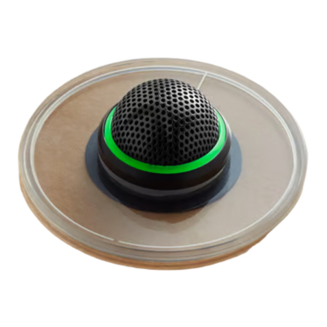
Among available microphonesare: alow-profilesurface-
mount model [AMS22], a gooseneck model for perma-
nent mounting [AMS24], a probe model[AMS26] with a
front pop-filter grille, and a lavalier model [AMS28]. Due
to the reinforcement of sound waves from the adjacent
boundary surface, the sensitivity of the surface-mount
model is twice as high [6 dB more] as that of the probe
model. The gooseneck modelis suppliedwith a cable, but
less connector.
The microphone connector is a standard 3-pin profes-
sional audio type [XLR]. Under most circumstances,
lengths of 150meters [500
ft]
or greater of goodquality
2-conductor shielded microphone cable can be used as
extensions between the microphone and the AMS mixer
microphone input. The same conductor must be wired to
the same numbered pin at both ends of the cable to en-
sure proper functioning of the units. The shield should be
connected topin1 atbothends of extensioncables.Good
practice dictates that microphones and extensioncables
be groundedonly tothe AMS mixer chassis ground.
2.
Microphone Inputs:
The AMS mixer is supplied with
either four or eight microphone inputs per unit. The
microphone inputs are designed for use only with Shure
AMS microphones; the Mixer will not operate with other
microphones; and Shure AMS microphones will operate
properly only with AMS mixers. The microphone input
connector is a female XLR type.
3.
Microphone Channel Gain Control:
When set to
the
"0"
posltlon [detented counterclockwise], the
mlcrophone is not
permitted
togate on. Turningthe con-
trol
clockwise
from this position permits the microphone
to gate on ether for sounds within ~tsacceptance angle
or by a connection to the Override log~cterminal [see
descr~pt~onof Logic Terminals below].
The Microphone Channel Gain control does not affect the
Dlrect Output level unless a jumper change has been
made for post-fader output as
described
in Paragraph 4
below.
4
Direct Output:
This provldes a non gated
microphone-level
s~gnalfromthe mtcrophone Thls output
behaves ltke a conventtonal cardloid h~gh-impedance
mlcrophone output It can be converted to balanced low
Impedance using a line matching transformer [Shure
A95UI An unbalanced low Impedance mlcrophone level
can be obtalnedby loadlng wlth a 100-ohmreslstor [con-
nected t~pto sleeve]
The '/4-1nchphone jack 1s supplled w~redpre-fader so that
the output 1s not affected by the posttionof ether the in-
div~dualChannelcontrolor the Mastercontrol,even when
the Channel control
IS
In the counterclockwise detent
["O"] position
Eachchannelcan be wlred post-fader by movingajumper
on the input module board [see section on Internal
Mod~ficationsfor deta~ls]Thls change causes the level at
the Dlrect Output to follow the settlng of the Channel
control
5.
ChannelLED Indicator:
A yellow LED indicator above
the Channel control l~ghtswhen the mlcrophoneis gated
on. The status of the Direct output is not related to the
LED.
6.
Hold Time:
This swltch determines how long the
microphone stays on after the user stops talklng. Thls
delayedturnoff br~dgespausesIn speechand reduces un-
necessary gatlng action. The 0.5-second posltion
minimizes microphone on-time, while the
I
.O-second
position bridges longer pauses.
For special applications, the 1.O-second positron can be
increasedto as long as 2 seconds by inserting a reslstor
[see Internal
Modifications
section for details].
7.
Off-Attenuation:
This switch determines the at-
tenuatlon of microphones that are not gated on. It is un-
necessary for "off" microphonesto be totally off to galn
the benef~tsof automatic mix~ng.Keepingthem slightlyon
at all times contributes to smooth unobtrus~vegatlng ac-
tlon.
The -15 setting of the Off-Attenuation switch is
recommended for most applications. The Variable set-
ting allows continuous adjustment of the Off-
Attenuat~onfrom minus infinityto -8.5dB [-8 setting]
by the screwdriver-slot adjustment directly above the
switch. [See sections on Link Jacks and on Theory of
Operation for further Information on Off-Attenuation.]
8.
Power Cord:
A 3-conductor cord and groundedplug
designedfor
connection
to 120Vac, 50160
Hz
outlets
only. To modifythe unlt for 240V, refer to the section
on Internal
Modifications.
9.
On-Off Switch:
Push-buttorr switch on the front
panel turns the power to the AMS mixer on and off.
10.
Power-On LED:
A green LED on the front panel
lights when the power is on.
11.
Normal LED:
A yellow LED on the front panelabove
the Power-On LED beg~nsto turn on when the line and
aux output levels are above approximately -20 dBV
[I
00
mV].
12.
Overload LED:
A red LED flashes when the
