Sefa AIR CLAM X User manual
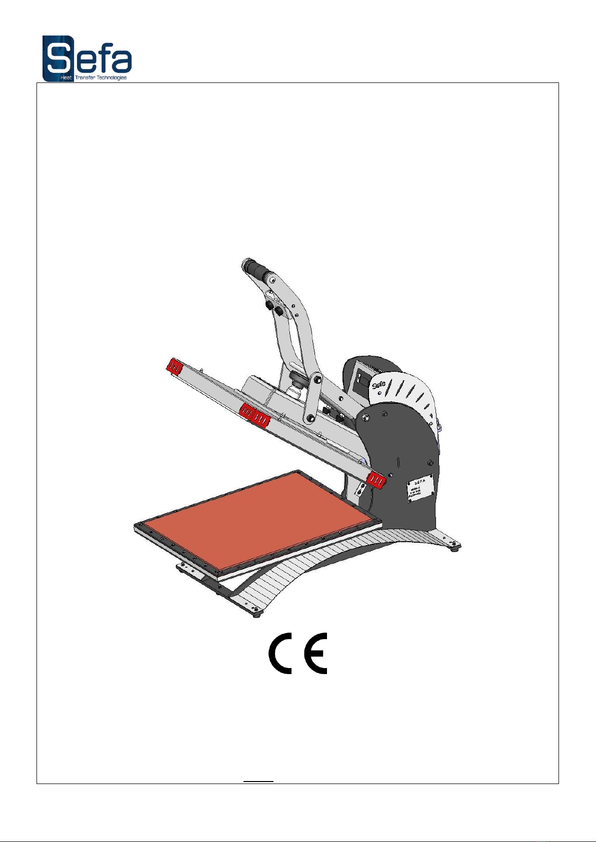
INSTRUCTION MANUAL
AIR CLAM X
S.E.F.A®
Z.I PASTABRAC
11260 ESPERAZA
FRANCE
Tel :33 (0)4.68.74.05.89 -Fax :33.(0)4.68.74.24.08
E Mail : contact@sefa.fr

V0412
Page N° 1
CONDITIONS OF GUARANTEE
The guarantee period starts the day of putting the equipment into service at the user’s place, materialized
by the return of the guarantee bill for a duration of two years, 8h per day meaning about 3000 hours.
The guarantee is strictly limited to our equipments, against the defects of matter and execution, with the
buyer’s responsibility to prove the known defects.
Our responsibility is limited to the obligation to rectify or replace free of charge the parts acknowledged as
faulty by ourselves, and there will no claim for any indemnity whatever the reason given.
Parts replaced under the guarantee:
remain our property
are the subject of an invoicing of deposit
A credit of cancellation is activated as soon as the faulty parts are returned.
The return will have to occur ONE MONTH MAXIMUM after the intervention
THE GUARANTEE DOES NOT COVER :
The retail consumables such as:
- Fuses, bulbs, joints, flexible devices, covers, nozzles, filters.....
- The supplies, which are not our own manufacturing, undergo the guarantee of their manufacturer.
THE GUARANTEE DOES NOT APPLY :
To replacements, nor repairs which would result from normal wear and tear of apparatus and machines, of
deteriorations and accidents coming from negligence, defect of monitoring and maintenance, defective use
or modifications without our written agreement.
In case of vice coming from the material supplied by the buyer, or a design imposed by the latter.
To repairs which would result from deteriorations or accidents occurred during transport.
To operations of maintenance and adjustments inherent in the use of the machine, and indicated in the
maintenance manual, such as:
- adjustments of intermediaries
- screwing of piping, etc…
For the pneumatic machines, any trace of detergent oil in the pneumatic circuit inhibits
the conditions of guarantee previously mentioned.
For any technical information or spare parts orders,
please give the reference number of the machine as well as its serial number

V0412
Page N° 2
SUMMARY
CONDITIONS OF GUARANTEE.............................................................................................................................................1
SUMMARY ..................................................................................................................................................................................2
SPECIFICATIONS......................................................................................................................................................................3
INSTALLATION OF THE MACHINE.....................................................................................................................................3
PARTS SUBJECTED TO WEAR AND TEAR.........................................................................................................................4
GENERAL POINTS ....................................................................................................................................................................5
ELECTRONIC BOX ...................................................................................................................................................................6
USAGE..........................................................................................................................................................................................7
1. CONTROL PANEL ...........................................................................................................................................................7
2. POWER ON .......................................................................................................................................................................7
3. SETTINGS.........................................................................................................................................................................8
a) TEMPERATURE ........................................................................................................................................................8
b) TIME...........................................................................................................................................................................8
4. HEIGHT ADJUSTMENT..................................................................................................................................................8
5. MAINTENANCE...............................................................................................................................................................8
CYCLE DESCRIPTION:............................................................................................................................................................9
QUICK REPAIR ADVICES.....................................................................................................................................................10
DIAGRAM..................................................................................................................................................................................11
NOTEMAKER...........................................................................................................................................................................12

V0412
Page N° 3
SPECIFICATIONS
Non contractual document : according to the technical progress, we reserve the right to modify the characteristics of our products.
INSTALLATION OF THE MACHINE
Unpack the machine from the box.
Install it on a safe table.
To move the press, make sure it is cold and handle it by grabbing both plates (upper and lower) at the same time
(machine closed).
Remove the screw labelled « Transport security » before opening the press.
Plug the machine electrically (230 Volt + Ground / 50 or 60 Hertz)
Plug the machine to a compressed air network (2 bar mini, 10 bar maxi).
Weight in running order
61 kg
40 kg
Height
534 mm
Depth
878 mm
Width
443 mm
Plate size
400 x 500 mm
Power supply
230 V Single phase + Ground 50/60 Hz
Power
2500 W
Amperage
11 A
Thermo regulator
Accurate to
+/- 2%
Range of control
0 à 250 °C
Timer
Accurate to
+/- 1%
Range of control
0s à 9min59s
Pressure
0.5 kg/cm²

V0412
Page N° 4
PARTS SUBJECTED TO WEAR AND TEAR
For any order:
precise the description, la reference and the quantity
Reference
Description
Quantity
CAR-CO1-EV0
ELECTRONIC CARD
1
REL-OM5
HEAT RELAY
1
RES-682
HEAT ELEMENT MICA 400x500 2500W
1
SON-189
SENSOR
1
FIN-231
MICROSWITCH WITH TONGUE
1
MOU-540
SILICONE RUBBER 400x500 mm
1
RES-BI2
GAS SPRING
1
RES-172
MECHANICAL SPRING
2
PLA-MEMBRANE
INFLATABLE MEMBRANE
1
FUS-153
FUSE 16 A
1
HOU-50
NOMEX COVER 400x500
1
V0412
Page N° 5
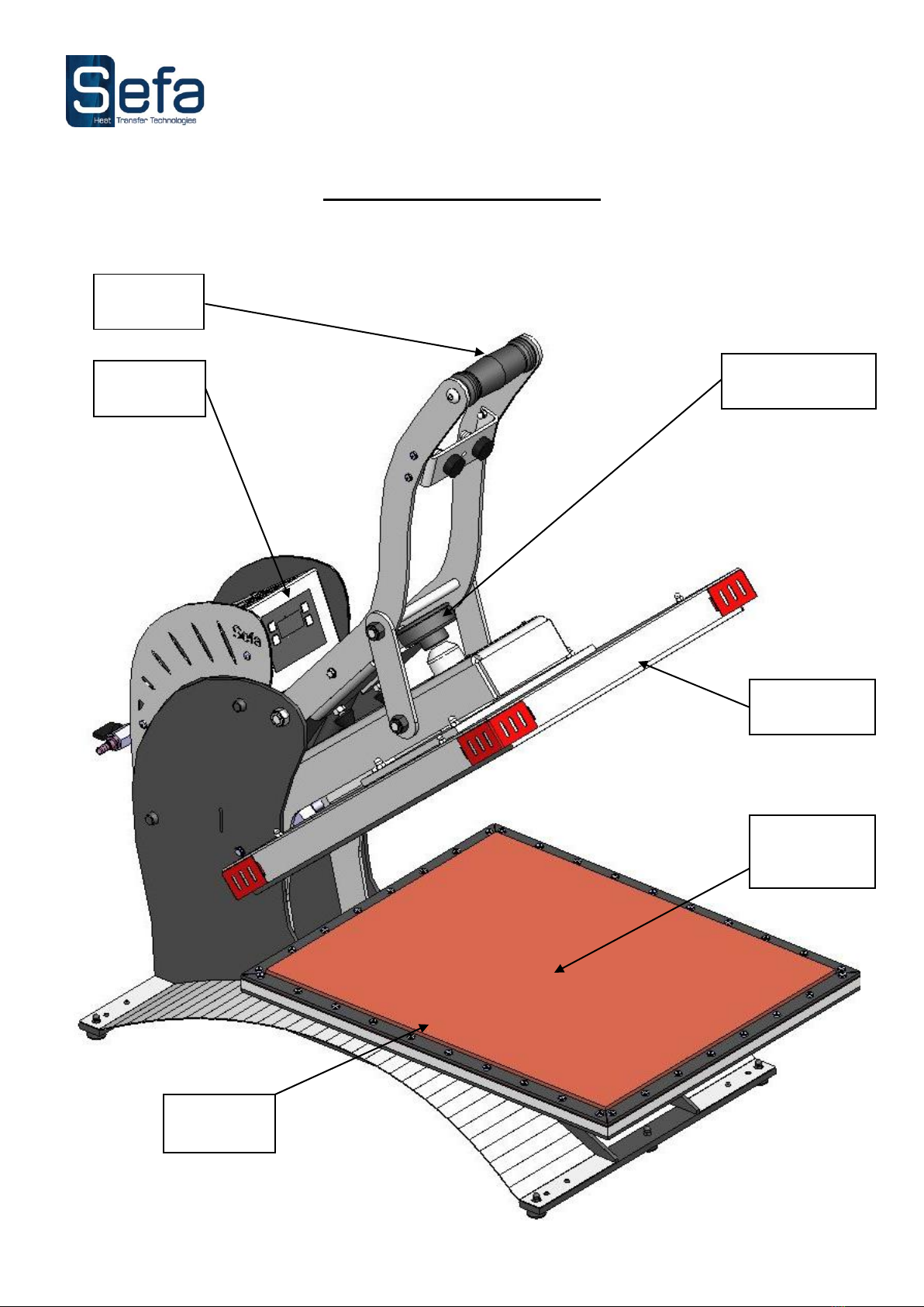
GENERAL POINTS
This heat seal press machine is standard to the labour laws to ensure the security of the user.
Its design allows it to ensure an intensive production while keeping a total reliability.
This press was designed for an operator working in front of the machine.
Control
panel
Heating plate
Silicon rubber
with inflatable
membrane
Handle
Height adjustment
wheel
Cold plate

V0412
Page N° 6
ELECTRONIC BOX
Relay
Filter
General
Switch and
fuse
Timer
Gate
Microswitch
Electro
distributor
Regulator
Electronic
card
Control
panel

V0412
Page N° 7
USAGE
It is recommended to read carefully the “instruction manual” before you start any pressing operation.
The press will have to be used by a qualified person who will have been informed of the risks which can be
caused by misuse of the equipment.
1.
CONTROL PANEL
2.
POWER ON
When switching the machine on, the regulator displays the temperature.
Selection
key
Down
Up
.
.
LED Indicator for
T° display
LED Indicator
for time display
Stop
button

V0412
Page N° 8
3.
SETTINGS
a) TEMPERATURE
Push twice the selection key (The T° LED indicator blinking)
Push the Up key to increase the temperature.
Push the Down key to decrease the temperature.
b) TIME
Push one on the selection key (The Time LED indicator blinking)
Push the Up key to increase the time.
Push the Down key to decrease de time.
4.
HEIGHT ADJUSTMENT
Turn the wheel on top of the heating plate:
clockwise to decrease the height of heating plate
anticlockwise to increase it
5.
MAINTENANCE
Every day:
Clean the heating plate with a dry cloth.
Depending on use:
Change the silicon rubber as soon as it is damaged or if it has lost its properties.

V0412
Page N° 9
CYCLE DESCRIPTION:
Turn on the machine by switching the power button.
Adjust the desired temperature at 180°C (or depending on the type of transfer) See SETTINGS § 3.a).
Adjust the time at 15 Sec (or depending on the type of transfer) See SETTINGS §3.b).
Adjust the height of the heating plate.
Install a T-shirt on the lower/cold plate.
Add your transfer material on top of it.
Wait until the plate reaches the setted temperature.
Lower the heating plate using the handle and hold it during 1 second.
When the plate is in contact with the T-shirt, the membrane inflates automatically.
At the end of the countdown, the membrane will deflate and the press will open automatically.
If you want to interrupt the cycle, you can do it by pushing the stop button located on the control panel:
the press will open automatically.
Nb : If the membrane is inflated, the press can not be locked. Hold the « STOP » button while lowering the handle
of the machine in order to deflate the membrane. When the membrane is deflated and the press locked, raise the
handle then release the “STOP” button.
V0412
Page N° 10
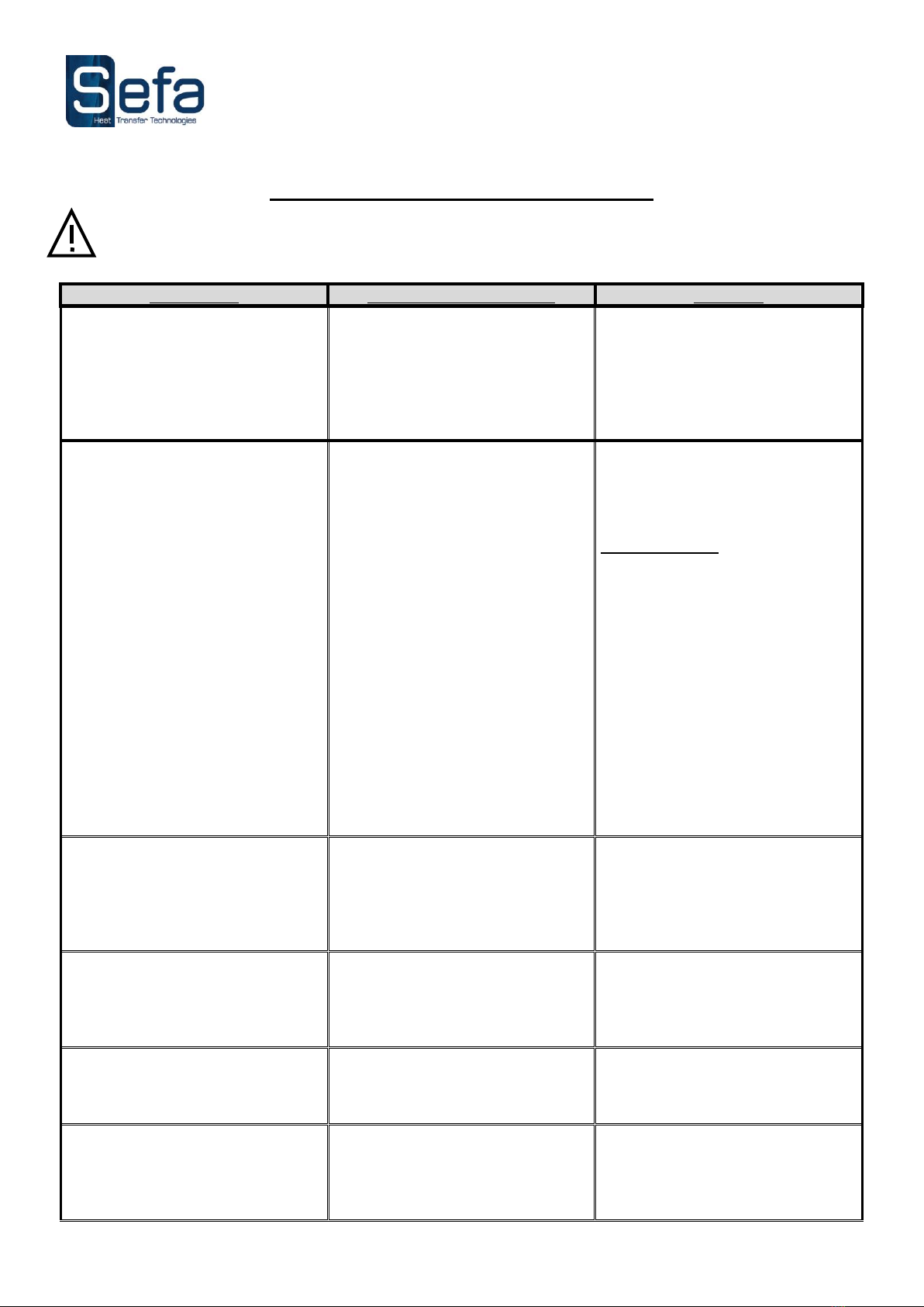
QUICK REPAIR ADVICES
All repair and maintenance operations should be done when the machine is turned off and unplugged from
the main electric power supply. The heating element can cause burns. The user must ensure the
temperature is below 25°C on the display, before any intervention.
SYMPTOMS
POSSIBLE BRAKDOWNS
REPAIRS
The press does not lock
The membrane is inflated
Hold the « STOP » button while
lowering the handle of the
machine in order to deflate the
membrane. When the membrane
is deflated and the press locked,
raise the handle then release the
“STOP” button
The plate will not heat
One of the fuses is out of order
The relay is damaged
Sensor out of order and/or
regulator displays ER1
If no light when the press goes
on, check the fuse, change it if
necessary.
GENERAL FUSE
located in a seating
next to the plug of the power supply
cable (16 A ). To access it, pull the
electrical cable off with the tip of a
pen or a screwdriver, lift the fuse
seating. You will find in a square
tube a spare fuse to replace the one
in the clip.
Check it out and change it if
necessary
Change the sensor
The plate overheats
The relay is stuck
The card is damaged
Change the relay.
Change the card
The timer doesn’t start
The microswitch isn’t activated
Make sure the Microswitch
tongue is touched by the
pressing arm of the machine.
The buzzer rings continuously
The Microswitch is stuck
Release the Microswitch tongue
or change it.
The press doesn’t stay closed
The Microswitch is stuck
Release the Microswitch tongue
or change it.

V0412
Page N° 11
DIAGRAM

V0412
Page N° 12
NOTEMAKER
------------------------------------------------------
------------------------------------------------------
------------------------------------------------------
------------------------------------------------------
------------------------------------------------------
------------------------------------------------------
------------------------------------------------------
------------------------------------------------------
------------------------------------------------------
------------------------------------------------------
Table of contents
Other Sefa Power Tools manuals

Sefa
Sefa ROTEX AIR V3 Series User manual

Sefa
Sefa DUPLEX PRO User manual

Sefa
Sefa DUPLEX PRO User manual

Sefa
Sefa INiTiUM User manual

Sefa
Sefa ROTEX V3 Series User manual

Sefa
Sefa LM V3 Series User manual

Sefa
Sefa LP 130 V3 User manual

Sefa
Sefa Initium iCAP 2 User manual

Sefa
Sefa DUPLEX MINI PRO User manual

Sefa
Sefa ROTEX AIR PRO User manual


Popular Power Tools manuals by other brands


Jet
Jet JDP-20MF Operating instructions and parts manual

Grizzly
Grizzly G0704 installation instructions

Kyocera
Kyocera Senco TN11G1 operating instructions

KRESS
KRESS 1-2+FIX instruction manual

Central Machinery
Central Machinery 42927 Assemble and operating instructions

Wacker Neuson
Wacker Neuson DPS 1850 Operator's manual


