Sefa DUPLEX PRO User manual

English version
INSTRUCTION MANUAL
DUPLEX PRO
S.E.F.A
®
Z.I PASTABRAC
11260 ESPERAZA
FRANCE
Tel: 33 (0)4.68.74.05.89 - Fax: 33.(0)4.68.74.24.08
E Ma l: conta[email protected]
English version
V0516
Page no. 1
WARRANTY TERMS
The warranty eriod shall come into effect on the day on which the equi ment is brought into service at the
user's remises, as attested on the returned warranty certificate and the delivery note, and shall run for
two years, based on a standard equi ment o erating schedule of 8 hours er day, i.e. 3,000 hours.
The warranty is strictly limited to our equi ment, and covers faulty materials and workmanshi , which the
urchaser shall be required to substantiate.
Our liability shall be limited to making good or re lacing free of charge arts that are acknowledged by us to
be defective, and no claims for damages for any reason may be made against us.
Parts re laced under warranty shall:
remain our ro erty
be invoiced on consignment
A credit note will be issued u on return of the faulty arts.
Returns must be made NO LATER THAN ONE MONTH after the work is erformed under warranty.
THIS WARRANTY DOES NOT COVER:
Commercially sourced wearing arts, material and equi ment such as:
- Fuses, bulbs, seals, hoses, nozzles, filters, etc.
- Material and equi ment not manufactured wholly by us, which are covered by the warranty of the
manufacturer thereof.
THIS WARRANTY DOES NOT EXTEND TO:
Re lacements or re airs arising from fair wear and tear of the a liances or machines, damage or accidents
arising from negligence, lack of su ervision or maintenance, im ro er use or alterations made without our
written consent.
Defects arising from material rovided by the urchaser or mandatory design requirements issued by the
urchaser.
Re airs made necessary by damage or accidents arising during carriage.
Normal maintenance and adjustment rocedures required during use of the machine, as set out in the
maintenance instructions, such as:
- adjustment of intermediate com onents
- tightening of i es, hoses, etc.
Any traces of detergent o l n the a r system of pneumat c mach nes shall nval date the
aforement oned warranty terms.
Quote the mach ne reference and ser al number when mak ng techn cal enqu r es or
order ng spare parts.

English version
V0516
Page no. 2
INDEX
WARRANTY TERMS .................................................................................................................................................................1
INDEX ..........................................................................................................................................................................................2
TECHNICAL DATA ....................................................................................................................................................................3
SETTING UP THE MACHINE..................................................................................................................................................3
OVERVIEW .................................................................................................................................................................................4
OPERATION ...............................................................................................................................................................................4
1.
SAFETY..................................................................................................................................................................................5
a) International symbols.........................................................................................................................................................5
b) Important safety precautions..............................................................................................................................................5
c) Safety features....................................................................................................................................................................5
Safety system checks...............................................................................................................................................................6
After an emergency stop.........................................................................................................................................................6
Instructions and manuals .......................................................................................................................................................6
2.
SWITCHING
ON ...................................................................................................................................................................7
3.
CONTROL
PANEL .................................................................................................................................................................7
4.
SETTINGS .............................................................................................................................................................................8
a) Temperature.......................................................................................................................................................................8
b) Timer..................................................................................................................................................................................8
c) Pressure .............................................................................................................................................................................8
d) Swing-away speed..............................................................................................................................................................8
5
.OPERATING
CYCLE..............................................................................................................................................................8
6.
ELECTRONIC
BOARD
SETTINGS........................................................................................................................................9
a) Presets................................................................................................................................................................................9
b) Settings menus....................................................................................................................................................................9
c) Sleep mode .......................................................................................................................................................................10
d) Machine settings ..............................................................................................................................................................10
e) User comfort settings .......................................................................................................................................................11
f) Energy saving mode..........................................................................................................................................................11
7.
FULL-AUTO
MODE
(OPTIONAL).......................................................................................................................................12
a) Cycle options: "foot pedal", "single workstation" and "full auto"..................................................................................12
b) Selecting a work mode:....................................................................................................................................................12
c) Setting the "post-press timer" (in automatic mode only): ................................................................................................12
PARTS LAYOUT .......................................................................................................................................................................13
WIRING AND PNEUMATIC DIAGRAM ............................................................................................................................14
SERVICING...............................................................................................................................................................................16
1.
REPLACING
WORN
PARTS................................................................................................................................................16
a) Silicone foam pads...........................................................................................................................................................16
b) Other parts.......................................................................................................................................................................16
2.
M
AINTENANCE
........................................................................................................................................................................16
3.
ELECTRONIC
BOARD
MESSAGES.....................................................................................................................................17
WEAR PARTS ...........................................................................................................................................................................17
TROUBLESHOOTING TIPS ..................................................................................................................................................18
MAINTENANCE LOG ..............................................................................................................................................................19

English version
V0516
Page no. 3
TECHNICAL DATA
Non-contractual document: we reserve the right to alter our roduct s ecifications in line with advances in technology.
SETTING UP THE MACHINE
TO BE PERFORMED BY QUALIFIED PERSONNEL
Do not hold the mach ne by the platens!
Remove the machine from its ackaging. The machine is secured to a allet.
Place the machine on a stable, level table using the carry bars.
Secure the machine to the table.
Place the foot edal on the floor.
Plug in the ress using the lug rovided (230 Volt + Earth / 50 or 60 Hz).
Connect the ress to your com ressed air su ly (min. 3.5 bar, max. 10 bar).
We ght n work ng order
150 kg
Height
713 mm
De th 1005 mm
Width 1071 mm
Platen size 400 x 500 mm
Power supply
220/240 V S ngle phase + Earth 50/60 Hz
Power consum tion
3200 W
Am rating
14A
Electron c temperature controller
Accuracy
+/- 1%
Setting range
0 to 255 °C
Electron c t mer
Accuracy
+/- 1%
Setting range
0 s to 11 min
Noise level Below 70 dB (A)
Max mum press ng force
925 daN
English version
V0516
Page no. 4
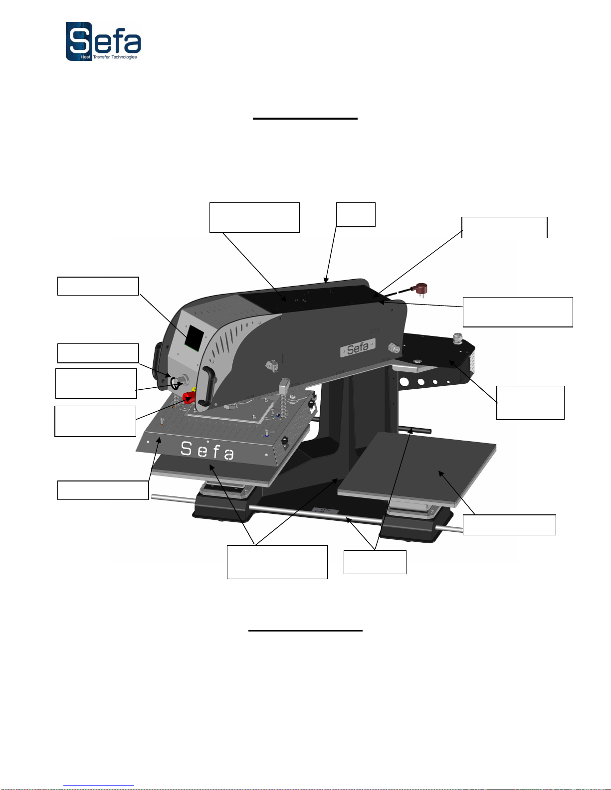
OVERVIEW
This heat ress has been designed to o erate at high out ut without risk to o erator safety in accordance with
article L 233-5 of the French labour code.
It has been designed for use by a single o erator ositioned in front of the machine.
OPERATION
Please read the O erating Manual carefully before o erating the ress.
The ress should be o erated by a qualified erson who is aware of the otential dangers arising from im ro er
use of the equi ment.
The factory-installed neumatic, electrical and mechanical settings rogrammed by our technicians and the safety
features must not be altered under any circumstances. SEFA acce ts no liability for roblems that may be caused
by the machine if such alterations are made.
Heat platen
Emergency
stop
Silicone foam pad
Detachable lower
platens
Filter
Touch screen
Cover +
electronic board Plug + fuse
Air inlet connection
Pressure gauge
Auto-swing
cylinder
Pressure
adjustment dial
Carry bars
Other manuals for DUPLEX PRO
1
Table of contents
Other Sefa Power Tools manuals

Sefa
Sefa DUPLEX MINI PRO User manual

Sefa
Sefa ROTEX AIR V3 Series User manual

Sefa
Sefa Initium iCAP 2 User manual

Sefa
Sefa INiTiUM User manual

Sefa
Sefa AIR CLAM X User manual

Sefa
Sefa LP 130 V3 User manual

Sefa
Sefa DUPLEX PRO User manual

Sefa
Sefa ROTEX AIR PRO User manual

Sefa
Sefa CLAM SPORT V3 User manual

Sefa
Sefa BR 180 PCAS User manual


