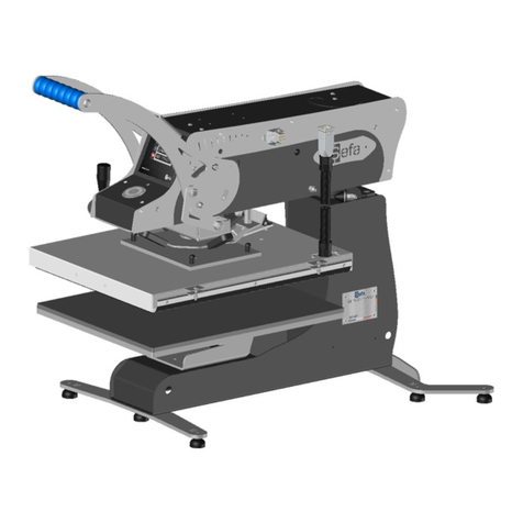
Sefa ROTEX AIR PRO User manual

English version
V0916
Page 1
INSTRUCTION MANUAL
ROTEX AIR PRO
S.E.F.A
®
Z.I PASTABRAC
11260 ESPERAZA
FRANCE
Tel: +33 (0)4.68.74.05.89 - Fax: +33 (0)4.68.74.24.08
E-ma l: contact sefa.fr

English version
V0916
Page 2
INDEX
I.
WARRANTY TERMS ........................................................................................................................ 3
II.
TECHNICAL DATA .......................................................................................................................... 4
III.
WEAR PARTS ............................................................................................................................. 4
IV.
USING THE PRESS ......................................................................................................................... 5
A.
SETTING UP THE MACHINE ................................................................................................................ 6
1.
Unpacking ................................................................................................................................................... 6
B.
TRANSFER CYCLE ............................................................................................................................... 6
C.
CONTROL PANEL ................................................................................................................................ 7
D.
OPERATION ....................................................................................................................................... 8
Presets ................................................................................................................................................................. 8
Settings menus ...................................................................................................................................................... 9
Sleep mode ........................................................................................................................................................... 9
Machine settings .................................................................................................................................................. 10
User comfort settings ........................................................................................................................................... 10
Energy saving mode ............................................................................................................................................. 10
E.
AUTO-SWING ................................................................................................................................... 11
F.
MAINTENANCE ................................................................................................................................. 12
V.
TROUBLESHOOTING TIPS ........................................................................................................... 13
VI.
WIRING and PNEUMATIC DIAGRAMS ......................................................................................... 14
VII.
MAINTENANCE LOG ................................................................................................................ 16

English version
V0916
Page 3
I. WARRANTY TERMS
•The warranty period shall come into effect on the day on which the equipment is brought into service at the
user's premises, as attested on the returned warranty certificate and the delivery note, and shall run for two
years, based on a standard equipment operating schedule of 8 hours per day, i.e. 3,000 hours.
•The warranty is strictly limited to our equipment, and covers faulty materials and workmanship, which the
purchaser shall be required to substantiate.
•Our liability shall be limited to making good or replacing free of charge parts that are acknowledged by us to
be defective, and no claims for damages for any reason may be made against us.
•Parts replaced under warranty shall:
-remain our property
-be invoiced on consignment
•A credit note will be issued upon return of the faulty parts.
Returns must be made NO LATER THAN ONE MONTH after the work is performed under warranty.
THIS WARRANTY DOES NOT COVER:
•Commercially sourced wearing parts, material and equipment such as:
-- Fuses, bulbs, seals, hoses, nozzles, filters, etc.
-Material and equipment not manufactured wholly by us, which are covered by the warranty of the
manufacturer thereof.
THIS WARRANTY DOES NOT EXTEND TO:
•Replacements or repairs arising from fair wear and tear of the appliances or machines, damage or accidents
arising from negligence, lack of supervision or maintenance, improper use or alterations made without our
written consent.
•Defects arising from material provided by the purchaser or mandatory design requirements issued by the
purchaser.
•Repairs made necessary by damage or accidents arising during carriage.
•Normal maintenance and adjustment procedures required during use of the machine, as set out in the
maintenance instructions, such as:
-adjustment of intermediate components
-tightening of pipes, hoses, etc. …
-
Any traces of detergent o l n the a r system of pneumat c mach nes shall nval date the
aforement oned warranty terms.
Quote the mach ne reference and ser al number when mak ng techn cal enqu r es or order ng spare
parts.

English version
V0916
Page 4
II. TECHNICAL DATA
Non-contractual document: we reserve the right to alter our product specifications in line with advances in technology.
III. WEAR PARTS
When order ng:
always quote the description, reference and quantity
Reference
Descr pt on
Quant ty
AFF-EL3’’5 HMI TOUCH SCREEN 1
CAR-EL I POWER BOARD
RES-CI1 GAS-OPERATED AUTO-SWING SPRING 1
RES-500X400-
3200W MICA HEATING ELEMENT 400x500 3200 W 1
SON-PT100 PT100 TEMPERATURE PROBE 1
TOI-4050 PROTECTIVE TEFLON SHEET FOR HEAT-PLATEN 1
MOU-540 SILICONE FOAM 400X500 mm 1
VER-SM21 COMPACT JACK Ø 140 mm 1
ELE-SM8 SOLENOID CONTROL VALVE 24V 1
DET-SM1 MAGNETIC REED SWITCH FOR ACTUATING JACK
ROTEX AIR PRO
We ght n work ng order
97kg
41kg
Height
681 mm
Depth 940 mm
Width 624 mm
Platen s ze 400 x 500 mm
Power supply
230 V S ngle phase + Earth 50/60 Hz
Power consumption
3200 W
Amp rating
14 A
Electron c temperature controller
Accuracy
+/- 1%
Setting range
0 to 220 °C
Electron c t mer
Accuracy
+/- 1%
Setting range
0 s to 9 min 30 s
Adjustable pressure
430 g/cm² at 6 bars and 560 g/cm² at 8 bars

English version
V0916
Page 5
IV. USING THE PRESS
This heat press has been designed for small production runs without risk to operator safety in accordance with
article L 233-5 of the French labour code.
This press has been designed for use by a single operator working from the front.
Air pressure
adjustment
wheel
Platen lowering
handle
Silicone pad
Filter
TOUCH SCREEN
control panel
Electronic board and
pneumatic components
Main switch
Detachable cold
lower platen
Dual-handed press
operating buttons
Heat platen
Emergency stop
button
Pressure gauge

English version
V0916
Page 6
A. SETTING UP THE MACHINE
1. Unpack ng
1. Remove the packing case from the machine.
2. Set up and secure the machine on its work table.
3. Make sure the press is cold before picking it up. Carry the press holding both platens (upper and lower),
which should be in the closed position.
4. Remove the transport safety screws before opening the press.
5. Plug in the press (230 Volt + Earth / 50 or 60 Hz).
B. TRANSFER CYCLE
1. Press the main switch at the back of the machine to turn the power on.
2. Set the temperature.
3. Set the pressing duration.
4. Set the pre-heat duration if necessary.
5. Adjust the pressure (to suit the type of transfer).
6. Place the T-shirt on the lower platen.
7. Position the transfer sheet correctly.
8. When the heat platen is at the correct temperature, press the dual-operated buttons to lower it into
position.
9. The timer will start when the platen is pressed against the T-shirt.
10. The press will open automatically when the timer has finished.
11. The cycle can be stopped early by pressing the stop button on the control panel. The press will open
automatically.
12. If the auto-swing is engaged, the machine will also swing open to the side automatically.

English version
V0916
Page 7
C. CONTROL PANEL
Current
temperature
reading and
temperature
adjustment field
Heating indicator
Date
Settings menu key
Increment-up, open next
menu, browse presetting
sub-menus
Increment-down, open
previous menu, browse
presetting sub-menus
Time
Main timer
Resettable counter
Presets

English version
V0916
Page 8
D. OPERATION
Presets
This menu contains nine pre-saved operating programs; up to five presets can be assigned to each program by
entering the required setpoints.
The operating programs must be suited to the processes you use. The temperature adjustment system is fine-
tuned for each program.
Available programs:
Customised: the system applies the user-defined settings keyed in at the control panel
Flex: for placing flex and flock
DTG 1: for drying pre-treated materials
DTG 2: for pressing pre-treated materials
SUBLI T: for sublimation printing on textiles
SUBLI R: for sublimation printing on rigid materials
SCREEN: for placing screen transfers
LASER: for placing laser transfers
QUICKFLEX: for placing flex in under 5 seconds
Browse between
programs
Browse between
program presets

English version
V0916
Page 9
Sett ngs menus
Press the green key in the centre of the screen to open the settings.
Click to access the required menu.
Press the arrow in the bottom centre of the screen to exit.
Sleep mode
Sleep mode keeps the machine temperature at a certain level for a certain length of time
Internal menu code
Error log (last 10 errors)
Counters
To previous screen
Machine settings
Energy saving mode
User comfort settings
Sleep mode
Diagnostic mode
End-of-cycle beeper time
setting
To next screen
To previous screen
Temperature in sleep mode
Start of sleep m
ode
End of sleep mode
O
N/OFF

English version
V0916
Page 10
Mach ne sett ngs
User comfort sett ngs
Energy sav ng mode
Energy saving mode reduces the machine temperature to the set temperature when the defined idle time has
elapsed.
Enable drying mode
The drying time is set at the
control panel with the
pressing time setpoint
Enable/disable buzzer
°C/°F
Machine operating
temperature range
On/Off
Temperature
Time

English version
V0916
Page 11
E. AUTO-SWING
When the cycle ends, the heat platen will lift up and the auto-swing system will rotate the press away to the side,
free of the heat platen.
You can disable this feature if you wish.
To enable this feature, first make sure the press is in the open position, then turn and push the thumbwheel down
as shown on the diagram below.

English version
V0916
Page 12
F. MAINTENANCE
•Daily:
Clean the heat platen with a dry cloth.
•According to use:
Replace the silicone foam pad at the first sign of damage or deterioration in quality.

English version
V0916
Page 13
V. TROUBLESHOOTING TIPS
The machine’s electrical power must be switched off and locked and tagged prior to any service repair
work.
The heat platen can cause burns. Check that the platen temperature reading on the display panel is below
25° C before handling.
PROBLEM POSSIBLE CAUSES SOLUTION
The platen does not heat up Faulty electronic board
Temperature probe not
working
Check and if necessary replace
Replace the temperature probe
The platen overheats The relay is stuck
The electronic board is
damaged
Replace the electronic board
Replace the electronic board
The timer does not count
down
The sensor is not being tripped
Check whether the sensor is tripped as the
descending heat platen moves past

English version
V0916
Page 14
VI. WIRING and PNEUMATIC DIAGRAMS

English version
V0916
Page 15

English version
V0916
Page 16
VII. MAINTENANCE LOG
The following checks and maintenance procedures should be performed at regular intervals to ensure that your
press remains in good working order and continues to provide reliable service.
Date Number
of hours
Pressure
check Air filter
check Cylinder
check
Condition
of foam
pad
Heating
element
check
Replaced
parts Observations
Tip - use the following abbreviations to help complete the log more quickly:
C: Checked W: Washed/Cleaned R: Replaced
Table of contents
Other Sefa Power Tools manuals
Sefa
Sefa AIR CLAM X User manual
Sefa
Sefa DUPLEX PRO User manual
Sefa
Sefa LM V3 Series User manual
Sefa
Sefa ROTEX AIR V3 Series User manual
Sefa
Sefa INiTiUM User manual

Sefa
Sefa BR 180 PCAS User manual
Sefa
Sefa LP 130 V3 User manual
Sefa
Sefa Initium iCAP 2 User manual
Sefa
Sefa CLAM 45M User manual
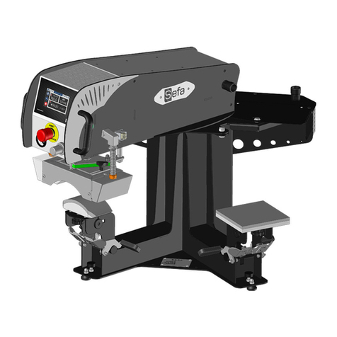
Sefa
Sefa DUPLEX MINI PRO User manual
Popular Power Tools manuals by other brands
Sparx
Sparx PS100 operating manual
Yokota
Yokota YLA140E-JQ manual
EINHELL
EINHELL BT-BJ 900 Original operating instructions

Clarke
Clarke CCT48 Operation & maintenance instructions
Baileigh Industrial
Baileigh Industrial DP-1850G Operator's manual
Sioux Tools
Sioux Tools IW100AI-8H Instructions and parts list
