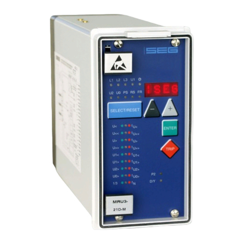
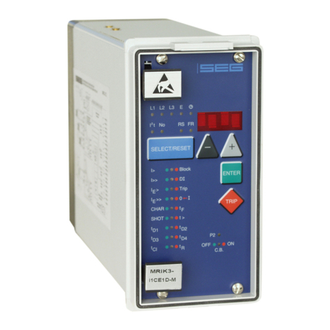
Seg MRI3-C User manual

MRI(K)3-C –Digital time overcurrent relay with Control
function and auto reclosing

2TB MRI(K)3-C 03.02 E
Contents
1 Introduction and Application
2 Characteristics and Features
3 Design
3.1 Connections
3.1.1 Analog input circuits
3.1.2 Output relays
3.1.3 Digital inputs
3.1.4 Low/High range of the digital Inputs
3.2 Password
3.2.1 Code jumpers
3.2.2 Password programming
3.2.3 Function of the output relays
3.3 Front plates
3.3.1 Indicating LEDs
3.3.2 Adjusting LEDs
3.4 Front plates (for ER/XR-relay types)
3.4.1 Indicating LEDs
3.4.2 Adjusting LEDs
4 Working principle
4.1 Analog circuits
4.2 Digital circuits
4.3 Status descriptions
4.3.1 „Inactive“
4.3.2 „Reclaim time“ tR
4.3.3 „AR-ready“
4.3.4 „AR-starting“ (dead time)
4.3.5 „AR-cycle“ (auto reclosing)
4.3.6 „AR-blocked“
4.3.7 „Fast Trip Mode“
4.3.8 „Blocking mode“
4.3.9 „Activating of AR“
4.3.10 Description of the status transition
4.3.11 AR information inputs
4.4 Functional sequence
4.4.1 Switching on MRIK3-C
4.4.2 Circuit breaker manual closing
4.4.3 Circuit breaker manual open
4.4.4 Starting AR
4.4.5 Unsuccessful reclosing
4.4.6 Successful reclosing
4.4.7 Repeated reclosing
4.4.8 Supervision of the circuit breaker ready
information
4.4.9 External blocking
4.4.10 Time sequence diagrams of MRIK3-C
4.4.11 The unit is programmed for two shots,
successful AR at the second shot
4.4.12 The unit is programmed for two shots,
unsuccessful AR
4.4.13 Manual closing of the circuit breaker to
faulty lines
4.4.14 Unsuccessful AR
4.5 Earth fault protection
4.5.1 Generator stator earth fault protection
4.5.2 System earth fault protection
4.6 Earth-fault directional feature
(ER/XR-relay type)
4.7 Control functions
4.7.1 Introduction
4.7.2 Interlocking / Password for control mode
4.7.3 Operating assignment of C.B. control
4.7.4 Changing the operating assignment
4.7.5 Saving the operating assignment
4.7.6 Remote switching on and off of the C.B.
4.7.7 Switching on or off the C.B. via the front
panel (LCAL)
4.7.8 Handling of the control function
4.7.9 Display for the control functions
4.7.10 LED-indication under normal mode
4.7.11 LED-indication auto reclosing conditions
(AR)
4.8 Requirement on the Main Current
Transformers
5 Operation and Adjustments
5.1 Displayed text for parameter settings
5.2 Setting procedure
5.3 Parameter levels
5.4 System parameters
5.4.1 Presentation of Measuring Values as
Primary Quantities on the Display
(Iprim Phase)
5.4.2 Display of residual voltage UE as primary
quantity (Uprim/Usec)
5.4.3 Voltage transformer connection for resi-
dual voltage measuring (3pha/e-n/1:1)
5.4.4 Operation cycle counter
5.4.5 I2*t Operation cycle counter
5.4.6 Rated -Frequency
5.4.7 Indication of pickup
5.4.8 Parameter Set Changeover Switch (P2)
5.5 Protection Parameters
5.5.1 Pickup current for phase overcurrent
element
5.5.2 Trip Characteristics for the Phase Over-
current Element (I>)
5.5.3 Tripping Time or Time Factor for the
Phase Overcurrent Element
5.5.4 Fast/Time tripping by switch ON of the
CB for the overcurrent lement
5.5.5 Reset Mode for the Trip Characteristics
in the Phase Current Path
5.5.6 Current setting for high set element
5.5.7 Trip delay for high set element
5.5.8 Fast/Time tripping by switch ON of the
CB for the short ciruit element
5.5.9 Pickup value for residual voltage (UE)
(ER/XR-relay types)

TB MRI(K)3-C 03.02 E 3
5.5.10 Pickup current for earth fault element (IE>)
5.5.11 WARN/TRIP changeover
5.5.12 Time current characteristics for earth fault
element (for E/X-relay types)
5.5.13 Tripping Time or Time Factor for the
Earth Fault Element
5.5.14 Fast/Time tripping by switch ON of the
CB for the earth fault low set element
5.5.15 Reset mode for inverse time tripping in
earth current path
5.5.16 Current setting for high set element of
earth fault supervision (IE>>)
5.5.17 Trip delay for high set element of earth
fault supervision
5.5.18 Fast/Time tripping by switch ON of the
CB for the earth fault high set lement
5.5.19 COS/SIN Measurement
(ER/XR-relay type)
5.6 AR Parameter
5.6.1 Number of AR shots
5.6.2 Fault time (tF)
5.6.3 Dead time (tD)
5.6.4 Close impulse time (tCI)
5.6.5 Reclaim time (tR)
5.6.6 Fault time activation
5.7 Control functions
5.7.1 Block/Trip-time
5.7.2 Time delay for ext. Trip
5.7.3 Dead time for Trip/Restore
5.7.4 CB failure protection
5.7.5 Release of the pick up relay for CB
failure protection
5.8 Interface Parameters
5.8.1 Adjustment of the Slave-Address (RS)
5.8.2 Adjustment of the Baud-Rate
5.8.3 Adjustment of the Parity
5.9 Fault Recorder (FR)
5.9.1 Fault Recorder
5.9.2 Number of fault recordings
5.9.3 Adjustment of the Trigger Event
5.9.4 Pre-Trigger time (Tvor)
5.10 Setting of the clock
5.11 Additional functions
5.11.1 Blocking the protection functions
5.11.2 Assignment of the output relays
5.11.3 Assignment of the AR functions
5.11.4 Function assignment of the digital inputs
5.11.5 Description of the digital input function
5.12 Measuring Value and Fault Indications
5.12.1 Measuring Value Indications
5.12.2 Units of the measuring values displayed
5.12.3 Indication of fault data
5.12.4 Fault Memory
5.13 Reset
5.13.1 Erasure of the Fault Memory
6 Notes on Relay Tests and Commissioning
6.1 Connection of the auxiliary voltage
6.2 Testing of Output Relays and LEDs
6.3 Secondary injection test
6.3.1 Test equipment
6.4 Example of test circuit for MRI(K)3-C
relays without directional feature
6.4.1 Checking the input circuits and
measured values
6.4.2 Checking the operating and resetting
values of the relay
6.4.3 Checking the relay operating time
6.4.4 Checking the high set element of the
relay
6.4.5 Test circuit for MRI(K)3 relay with earth-
current directional recognition
(ER/XR models)
6.4.6 Checking the auto reclosing function
6.4.7 Checking the circuit breaker position
6.4.8 Checking the AR blocking function
6.4.9 Checking the external blocking and
reset functions
6.4.10 Testing the external blocking with
Block/Trip function
6.4.11 Test of the CB failure protection
6.5 Primary Test
6.6 Maintenance
7 Technical Data
7.1 Measuring input
7.2 Common data
7.3 Setting ranges and steps
7.3.1 System parameter
7.3.2 Time overcurrent protection (I-type)
7.3.3 Earth fault protection (E/X-type)
7.3.4 Earth fault protection (ER/XR-type)
7.3.5 AR Parameter
7.3.6 Control Function
7.3.7 Interface parameter
7.3.8 Parameter for the fault recorder
7.4 Tripping characteristics
7.4.1 Inverse time overcurrent protection relay
7.4.2 Determination of earth fault direction
(MRI(K)3-ER/XR)
7.5 Tripping characteristics
7.6 Output relays
8 Order form

4TB MRI(K)3-C 03.02 E
1 Introduction and Application
The digital net protection relay MRI(K)3-C an universal
time - over -current and earth fault relay with integrated
control- and supervision function as well as optional an
integrated auto reclosing function The earth fault pro-
tection is applicable for insulated and compensated
grids. The controlling of the circuit breaker take place
by the means of the front plate via push button in the
case of a local operation, the remote operation can
be done via digital inputs or via the serial communica-
tion interface.
The earth-fault supervision is either realised in Holm-
green connection or by means of a core-type current
transformer.
The MRI(K)3-C is available with rated currents of 1 A
or 5 A.
2 Characteristics and Features
•Microprocessor technology with self-supvervision,
•Measuring of phase currents as RMS value,
•Digital filtering of the earth current with discrete Fou-
rier analysis, by which the influence of interference
signals, such as harmonics and transient DC com-
ponents during an earth-fault are suppressed.
•Two sets of parameters,
•Operation cycle counter,
•Switch off power Measuring of the switch off power
of the CB power,
•Suppression of an LED indication after activation
(LED flash),
•Selectable protective functions : Definite time over-
current protection (DMT) and inverse time overcurrent
protection (IMT),
•Selectable IMT trip characteristics of IEC 255-4:
Normal inverse (Type A)
Very inverse (Type B)
Extremely inverse (Type C)
Special-purpose characteristics
•Reset mode for DMT/IMT trip characteristics is se-
lectable,
•Definite element for short-circuit high-speed trip
•Defined time overcurrent protection without direc-
tional feature (DEFT)
•Inverse time overcurrent protection without directional
feature (INV)
•Two element defined- or inverse time earth fault pro-
tection,
•Optionally with integrated directional feature for the
earth fault element.
•Control of the CB via potential free auxiliary relays,
•Supervision of the CB via digital wide range inputs,
•Remote indication of the CB position via serial inter-
face.,
•CB failure protection,
•Display of the measuring values as primary quanti-
ties,
•Measuring of the phase currents during short-circuit
free operation,
•Blocking of the individual protective elements or the
trip elements can be set freely,
•The protective functions can be freely allocated to
the output relays. (RelayMatrix),
•automatic auto reclosing (optional),
•free assignment of protective function for every re-
closing separately adjustable,
•Free assignment of the input function to the digtial
input,
•Saving of trip values and the switch-off times (tCBFP) of
25 fault events (voltage fail-safe),
•Recording of up to 8 fault events with time stamp,
•Display of date and time,
•Trip via digital inputs,
•Rack mounting, with self-acting short-circuit mecha-
nism for CT circuits,
•Possibility of serial data exchange via the RS485 in-
terface, optionally with SEG RS485 Pro-Open-Data
Protocol or Modbus Protocol.

TB MRI(K)3-C 03.02 E 5
3 Design
3.1 Connections
Figure 3.1: Connection diagram MRIK3-ICE/MRI3-ICE
Figure 3.2: Connection diagram MRIK3-ICER/MRI3-ICER

6TB MRI(K)3-C 03.02 E
P1
P2
S1
S2
P1
P2
S1
S2
P1
P2
S1
S2
I1
I2
I3
IE
L1.1
B3
B4 L1.2
L2.1
B5
L2.2
B6
L3.1
B7
L3.2B8
B1
B2
L
1
L2
L3
Figure 3.3: Measuring of phase currents and earth current detection
in Holmgreen connection (IE)
This kind of connection can be used where three
phase CTs are available and a combination of phase
and earth current measuring is required.
Figure 3.4: Measuring of earth current with core-type CT (IE)
With the combination of phase and earth current
measuring, CTs to be connected according to Figure
3.3 or Figure 3.4.

TB MRI(K)3-C 03.02 E 7
3.1.1 Analog input circuits
The analog input signals of the phase currents IL1 (B3 -
B4), IL2 (B5 - B6), IL3 (B7 - B8) and the earth current IE
(B1 - B2) are fed to the protection device via separate
input CTs. The current measuring quantities are gal-
vanical decoupled, analogously filtered, and then fed
to the analog/digital converter.
For the unit type with earth fault directional features
(ER/XR-relay type) the residual voltage from the open
delta winding can directly be connected to A3 and
A2.
See chapter ??? for voltage transformer connections
on isolated/compensated systems (direction feature of
the aerth fault element)
3.1.2 Output relays
The MRI(K)3-C has 5 output relays. Two of these re-
lays with two change-over contacts and three relays
with one change-over contact each are used for sig-
nalling. The protective functions can be freely allo-
cated except of those for the self-supervision relay.
•Relay 1: C1, D1, E1 and C2, D2, E2
•Relay 2: C3, D3, E3 and C4, D4, E4
•Relay 3: C5, D5, E5
•Relay 4: C6, D6, E6
•Relay 5: Self-supervision C7, D7, E7
All relays are operating according to the n. o. princi-
ple with the exception of the self-supervision relay,
which operates acc. to the n. c. principle.
3.1.3 Digital inputs
The MRI(K)3-C has 7 digital inputs with fixed func-
tions. The input functions can be selected free for each
digital input. All inputs have a common reference point
: Terminal D8. (See chapter 5.11.4/5.11.5)
Terminal Function Code
jumper
C8 Digital Input 1 2
E8 Digital Input 2 1
A2 Digital Input 3 3
A5 Digital Input 4 4
A6 Digital Input 5 7
A7 Digital Input 6 6
A8 Digital Input 7 5
3.1.4 Low/High range of the digital
Inputs
The MRI(K)3-C is equipped with a wide-range power
supply unit and hence the supply voltage is freely se-
lectable. The switching threshold of the digital inputs,
however, has to be fixed in compliance with the sup-
ply voltage. Two different switching thresholds can be
adjusted:
Range Plug UAB UAN
Low Plugged in <= 8V >= 10V
High Open <= 60V >= 70V
Figure 3.5: Code jumpers

8TB MRI(K)3-C 03.02 E
3.2 Password
3.2.1 Code jumpers
Behind the front plate of the MR-relays there are three
code jumpers to preset the following functions:
•Password programming
•Output relay functions
The following figure shows the position and designa-
tion of the code jumpers:
Figure 3.6: Code jumpers
3.2.2 Password programming
The two different Password are assign to seperate
password sections. Password 1 ( Code jumper 1 )
With this password all protection parameter are
changeable. Password 2 ( Code jumper J2 ) With this
password it is allowed to change the mode of the re-
lay from “remote control” to “local control” and also al-
lowed to control the CB. (See Chap. 4.7.8) The pro-
cedure for password programming is described in
Chapter 4.4 of the description MR - general.
3.2.3 Function of the output relays
The following functions of MR output relays can be
preset:
•Reset of the output relays manually or automati-
cally
The alarm relays are activated according to the preset-
ting:
Code jumper 3 OFF:
All output relays will be reset automatically after the
fault has been rectified, (e.g. when the fault current is
interrupted).
Code jumper 3 ON:
All output relays remains activated and must be reset
after fault clearence.
•Manually: By pressing push button
<SELECT/RESET>
•External: By connecting aux. voltage to C8/D8
Via RS 485 interface (see chapter 5.11.4)
To let the parameter change take effect, the auxiliary
voltage has to be switched on and off again after the
code jumpers are plugged or unplugged.
* This functions is only aviable with relays without AR
function ( Type MRI3-C)
Code jumper Function Code jumper
position
Operation mode
J1 Password 1** OFF Normal position
general ON Password selection (see general description MR chapter
4.4)
J2 Password 2** OFF Normal position
Control-level ON Password selection (see general description MR chapter
4.4)
J3* Reset OFF Output relays will be reset automatically
ON Output relays will be reset manual/external/via soft-
ware
Table 3.1: Summary of coding possibilities
** are both code jumpers set, it is not possible to change the password.

TB MRI(K)3-C 03.02 E 9
3.3 Front plates
Figure 3.7: Front plate MRI(K)3-ICE
Figure 3.8: Front plate MRI3-ICE
The LEDs No, RS and on the MRI(K)3-C emit a yellow
light, all other LEDs are bi-coloured. The LEDs at the left
next to the alphanumerical display give a green light
during measuring and a red one when a fault signal
occurs.
The LEDs underneath the <SELECT/RESET> - push but-
ton emit a green light during adjustment and inquiry of
the setting quantities left to the LEDs. They show a red
light if the printed setting quantities right to the LEDs
are activated.
3.3.1 Indicating LEDs
L1, L2, L3 Indication of the phase currents
E Indication of the earth current
I2t Indication for the composite switch
off power of the CB.
No operation cycle counter
!Date and time
CB red CB ist switched on
CB green CB is switched off
CB blinking CB has faults
3.3.2 Adjusting LEDs
I> Overcurrent setting
tI> Tripping time for the overcurrent
I>> Short-circuit setting
tI>> Tripping for the short-circuit
IE> Earth overcurrent setting
tIE> Tripping time for the earth overcurrent
IE>> Earth short circuit setting
tIE>> Tripping time for the earth short-circuit
CHAR Selection of characteristics
tRST Reset-Mode for the time delay of the
protection elements
t> emits in combination with all time
delay settings
DI Assignment of input functions to the
digital inputs.
Trip ext. tripping
Block Trip/Blockage time
Fast Fast/Time function
I²t> Pick up level for the composite switch
off power
SHOT number off AR shots
tF fault time
tD1 dead time before 1. AR
tD2 dead time before 2. AR
tD3 dead time before 3. AR
tD4 dead time before 4. AR
tCl close impuls time
tR reclaim time
FR Parameter for the fault recorder
RS Setting of the relay address
P2 Parameterset 2 ist active

10 TB MRI(K)3-C 03.02 E
3.4 Front plates (for ER/XR-relay types)
Figure 3.9: Front plate MRI(K)3-ICER
Figure 3.10: Front plate MRI3-ICER
The LEDs IP, IQ, RS and FR on the MRIK3-ICE and
MRI3-ICE emit a yellow light, all other LEDs are bi-
coloured. The LEDs at the left next to the alphanumeri-
cal display give a green light during measuring and a
red one when a fault signal occurs.
The LEDs underneath the <SELECT/RESET> - push but-
ton emit a green light during adjustment and inquiry of
the setting quantities left to the LEDs. They show a red
light if the printed setting quantities right to the LEDs
are activated.
3.4.1 Indicating LEDs
L1, L2, L3 Indication of the phase currents
E Indication of the earth current
IPIndication of the active component of
the earth fault current
IQIndication of the reactive component
of the earth fault current.
!Date and time
CB red CB ist switched on
CB green CB is switched off
CB blinking CB has faults
3.4.2 Adjusting LEDs
I> Overcurrent setting
I>> Short-circuit setting
IE> Earth overcurrent setting
IE>> Earth short circuit setting
CHAR Selection of characteristics
t> lights in combination with all time de-
lay settings.
DI Assignment of the input functions to
the digital inpus
Trip ext. tripping
Block Trip/Blockage-time
Fast Fast/Time function
SHOT Number of AR shots
tF max. fault time
tD1 dead time before 1. AR
tD2 dead time before 2. AR
tD3 dead time before 3. AR
tD4 dead time before 4. AR
tCl max close impuls time
tR reclaim time
FR Parameter for the fault recorder
RS Setting of the relay address
P2 Parameterset 2 ist active

TB MRI(K)3-C 03.02 E 11
4 Working principle
4.1 Analog circuits
The incoming currents from the main current transform-
ers on the protected object are converted to voltage
signals in proportion to the currents via the input trans-
formers and burden. The noise signals caused by in-
ductive and capacitive coupling are surpressed by an
analog R-C filter circuit.
The analog voltage signals are fed to the A/D-
converter of the microprocessor and transformed to
digital signals through Sample- and Hold-circuits. The
analog signals are sampled at 50 Hz (60 Hz) with a
sampling frequency of 800 Hz (960 Hz), namely, a
sampling rate of 1.25 ms (1.04 ms) for every measur-
ing quantity.
4.2 Digital circuits
The essential part of the MRI(K)3-C relay is a powerful
microcontroller. All of the operations, from the analog
digital conversion to the relay trip decision, are carried
out by the microcontroller digitally. The relay program
is located in an EPROM (Electrically-Programmable-
Read-Only-Memory). With this program the CPU of the
microcontroller calculates the three phase currents and
ground current in order to detect a possible fault situa-
tion in the protected object.
For the calculation of the current value an efficient digi-
tal filter based on the Fourier Transformation (DFFT -
Discrete Fast Fourier Transformation) is applied to sup-
press high frequency harmonics and DC components
caused by fault-induced transients or other system dis-
turbances.
The calculated actual current values are compared
with the relay settings. If a phase current exceeds the
pickup value, an alarm is given and after the set trip
delay has elapsed, the corresponding trip relay is ac-
tivated.
The relay setting values for all parameters are stored in
a parameter memory (EEPROM - Electrically Erasable
Programmable Read-only Memory), so that the actual
relay settings cannot be lost, even if the power supply
is interrupted.
The microprocessor is supervised by a built-in "watch-
dog" timer. In case of a failure the watchdog timer re-
sets the microprocessor and gives an alarm signal, via
the output relay "self supervision".
4.3 Status descriptions
Reaction to protection events is possible at any time
unless blocking is expressly desired (refer to 5.11.1).
In the inactive and blocked state auto reclosing is not
possible.
For the explanation of the functional sequence the fol-
lowing six status transitions are defined.
4.3.1 „Inactive“
The relay MRIK3-C is in "inactive" status if one of the
following conditions is fulfilled:
•The circuit breaker is in position "OFF",
•the unit is in "blocked" status,
•the unit is not in "starting/cycle" status
4.3.2 „Reclaim time“ tR
The relay MRIK3-C is in "reclaim time" status (tR) when
the reclaim time
•has not yet expired or
•not interrupted by other incidents.
4.3.3 „AR-ready“
The relay MRIK3-C is in position "AR-ready" status
when the following conditions are fulfilled:
•The circuit breaker is in position "ON",LED CB
emit red light
•the reclaim time has expired,
•the unit is not in "blocked" status,
•the unit is not in "starting cycle" status.
Only in "AR-ready" status a reaction of the AR-unit to
the protection incidents is possible!
4.3.4 „AR-starting“ (dead time)
In "AR-starting" status the start conditions for an auto-
matic reclosing by means of the protection commands
and the circuit breaker position are checked.

12 TB MRI(K)3-C 03.02 E
4.3.5 „AR-cycle“ (auto reclosing)
The reclosing commands are carried out in "AR-cycle"
status by means of the conditions and the presetting.
The results (AR successful or unsuccessful) are evalu-
ated accordingly.
4.3.6 „AR-blocked“
Unit MRIK3-C changes immediately to "AR-blocked"
status when an external or internal blocking signal
(A2-A3) exists. (activation via assigned digital input,
see Chap. 5.11.4). No auto reclosing is possible in
"AR-blocked" status.
4.3.7 „Fast Trip Mode“
By way of the function "Assignment of the AR functions"
it is possible to activate or deactivate a Fast Trip func-
tion for each AR stage and for each protective func-
tion. This is applicable for tripping before the 1st AR up
to tripping after the last AR. (see chapter 5.11.3)
4.3.8 „Blocking mode“
By way of the function "Assignment of the AR functions"
it is possible to activate or deactivate a protection
function for each AR stage. This is applicable for trip-
ping before the 1st AR up to tripping after the last AR.
(see chapter 5.11.3)
4.3.9 „Activating of AR“
Prior to every AR it is possible to stipulate which kind
of tripping (I> or I>>, etc.) will lead to automatic re-
closing. This can be separately fixed for each AR
stage. (see chapter 5.11.3)
4.3.10 Description of the status transition
to
from
inactive reclaim time ready starting
(dead time)
cycle (auto
reclosing)
blocked
inactive C.B. manual
ON
external block-
ing signal
reclaim
time
reclaim time
expired
external block-
ing signal
ready C.B. OFF protection ener-
gized and/or
tripped and C.B.-
energy OK
external block-
ing signal
starting starting
conditions not
fulfilled
start signal
interrupted
start condi-
tions fulfilled
(fault time,
C.B. OFF
etc.)
external block-
ing signal
cycle AR takes place external or in-
ternal blocking
signal
blocked external
reset of
blocking
Table 4.1: AR-status transition matrix
From Table 4.1 you can detect what status transitions
of MRIK3-C are possible. When the unit is for instance
in "cycle" status (see also para. 4.3) only two status
transitions are possible:
•status transition to "ready"-status when the auto re-
closing takes place
•status transition to "blocked" status by external or
internal blocking.
The grey shaded sections indicate that no transition is
possible.

TB MRI(K)3-C 03.02 E 13
4.3.11 AR information inputs
By means of the information inputs the MRIK3-C de-
cides whether and when automatic reclosing may take
place. The functions are assigned via the function as-
signment of the digital inputs as far as they are re-
quired. (refer to chapter 5.11.5)
If one of the three CB position indicators described in
the following is activated, it must also be used be-
cause otherwise no correct function indication is pos-
sible.
CR = "CB ready" signal (e.g. motor switch or spring
power storage)
With this function the CB ready message is signalled.
CI = "CB feedback CB – ON"
With this function the CB position ON is signalled.
Signal = 1 = CB is switched on.
CO = "CB feedback CB – OFF
With this function the CB position OFF is signalled.
Signal = 1 = CB is switched off.
Note
If both functions are assigned to one digital input, a
CB ON position is only recognised if 1 is recognised
via the CI function and 0 via the CO function. For the
OFF position both signals must indicate a negative
signal. All other position indications lead to a CB fault
signal. This is visually indicated by the flashing CB
LED. (refer to chapter 4.7.11)
AR blocked
With this function an AR can be blocked at any time.
If the function has been set, the LED 0←1.
SY= SY = Synchronisation signal
This function permits an extension of the dead times tD.
If this function has been activated, there is a waiting
time of 150 s for the synchronisation signal after the
dead times have expired. If the input has not been set
after this period has expired, the MRIK3-C stops the
AR cycle. The display shows "S/E?". If the digital input
is activated during this period, the ON signal is set
without delay.
4.4 Functional sequence
4.4.1 Switching on MRIK3-C
Is the C.B. to be supervised in OFF position while
“switching ON” the MRIK3-C, the unit changes into
"inactive" status when applying the auxiliary voltage.
The LED "CB" on the front plate remains dark. The unit
is not ready for auto reclosing. If, however, the C.B. is
in “ON” position when applying the auxiliary voltage,
the unit changes into "reclaim time"-status and remains
blocked during this period (from 1 s to 300 s adjust-
able).
This is indicated at the unit by LED tR. After expiration
of the reclaim time the unit changes to "ready" status
and is then ready for auto reclosing. LED "CB" signal-
izes this status.
In case unit MRIK3-C is in "blocked" status before aux-
iliary voltage failure occurred, this condition remains
also after recurrence of auxiliary voltage.
The LED CB shows the position of the C.B.
4.4.2 Circuit breaker manual closing
If the circuit breaker is closed manually to a faultless
line, first the unit remains blocked during the reclaim
time (adjustable 1 - 300 s) and then changes to
"ready" status. If the circuit breaker is closed manually
to a faulty line (e.g. short circuit), no AR follows. Unit
MRIK3-C remains in "inactive" status after protection
tripping. By switching the circuit breaker on manually it
is possible to choose whether the CB is to switch off
with or without delay action in case of connection to a
faulty line. Setting is done separately for each protec-
tion stage. (refer to chapter 5.5.4; 5.5.8; 5.5.14 und
5.5.18)
4.4.3 Circuit breaker manual open
When switching off the circuit breaker manually the
unit changes at once without time delay from "ready"
status into "inactive" status. Auto reclosing is not possi-
ble. The LED CB emit green light.

14 TB MRI(K)3-C 03.02 E
4.4.4 Starting AR
When the information "protection energized" and "pro-
tection tripping" is applied, the unit changes from
"ready" status to "starting" status. The LED "AR" lights
up. The "starting" status begins with the start of a fault
timer (tF from 0.1 s to 2.0 s adjustable).
The LED tF lights up red. A tripping timer (set at 0.2 s)
is started when the mains protection tripping command
takes place before expiration of the set fault time.
(C.B. must be tripped within this time). The "start condi-
tions not fulfilled" is evaluated and the MRIK3-C is
locked for the duration of the reclaim time when there
is a time difference between mains protection-
energized and tripping, which is larger than the set
"fault time". The LED tF flashes red. If the OFF-signal of
the C.B. appears before expiration of the tripping
timer, it is evaluated as "start condition fulfilled" and
the unit changes over to "cycle" status. The LED tF ex-
tinguishes. During the switch-off procedure of the circuit
breaker the MRIK3-C waits for feedback from the C.B.
This feedback must come within 0.2 s. If the OFF-
signal does not appear, however, before expiration of
the tripping timer, it will be evaluated as "start condi-
tion not fulfilled" and the unit changes to „inactive“
status. The LED CB flashes and the Display shows
„CB??“. Tripping timer: Time from the beginning of the
tripping command until receiving of the C.B. check-
back signal.
4.4.5 Unsuccessful reclosing
After the start condition has been fulfilled the unit
changes to "starting" status. Now the dead time tD is
started. The corresponding LED flashes.
Unit MRIK3-C can be programmed for reclosing of
one to four times. For each reclosing a dead time has
to be set (tD1 to tD4). When the dead time has expired
and also the other reclosing conditions have been ful-
filled, the reclosing command is given to the circuit
breaker. The reclosing conditions are the responsibility
of the synchonisation command if the function is con-
figured via the digital inputs. The CB must be ready
and in switched-off status. The reclosing command re-
mains either as long as the ON-signal from the circuit
breaker appears or the close-impuls-timer (tCL) has ex-
pired.
The LED tCL lights up for the duration of the close im-
pulse. When the CB-ON message occurs, the LED tCL
extinguishes. After expiration of the ON impulse timer
the LED tCI starts flashing and the display shows "CB??"
In the last case a failure of the circuit breaker is sub-
jected. With the beginning of the reclosing command
the reclaim timer is started. When a new “OFF-signal”
of the circuit breaker appears within the reclaim time
and after the last permissible AR, an unsuccessful re-
closing will be detected.
The LED 0→I lights up red and the display shows
„OPEN“. Then the unit quits the "cycle" status and
changes to the "inactive" status. Simultaneously a relay
can be activated which indicates unsuccessful auto re-
closing.
4.4.6 Successful reclosing
If there is no “OFF-signal” of the circuit breaker and no
protection tripping within the reclaim time a successful
reclosing will be detected.
During the reclaim time the display shows „CLOS“ and
the LED 0→I lights up green.
The unit now quits the "cycle" status, changes over into
the "ready" status and is ready for the next reclosing.
The LED AR extinguishes and the CB LED lights up. The
display shows „ISEG“.
4.4.7 Repeated reclosing
Is the MRIK3-C programmed for more than single re-
closing a further dead time is started after a new “OFF-
signal” from the circuit breaker has appeared. After
expiration of this dead time a new reclosing command
follows.
4.4.8 Supervision of the circuit breaker
ready information
Because the supervising unit of the circuit breaker en-
ergy store operates often after the first fast switch off
(see also para. 3.1.2), the signal "C.B. not AR-ready"
is not evaluated anymore after an introduced reclos-
ing. The C.B. ready information is checked before an
introduced AR for further ARs. There will be a reclosing
when the "circuit breaker ready" had been given be-
fore the begin of the reclosing cycle. If not, the LED CB
flashes and the display shows „S/E?“.
4.4.9 External blocking
The AR-relay is blocked if the external AR-block input is
activated. The LED 0←I is alight.
When the reclosing shot is set to „EXIT“, the MRIK3
can also be blocked at site. (see chapter 5.11.5)

TB MRI(K)3-C 03.02 E 15
4.4.10 Time sequence diagrams of MRIK3-C
Legend:
4.4.11 The unit is programmed for two shots, successful AR at the second shot
Figure 4.1: Two shots, second AR successful
In case of a short circuit an energizing follows with
subsequent tripping of the protection relay. The circuit
breaker is switched off and the short circuit is cleared.
After expiration of the dead time tD1 unit MRIK3-C
gives the reclosing command to the circuit breaker.
If the fault still exists the protection relay trips again
and the above mentioned procedure is repeated as
long until either the fault was removed (here after the
second reclosing) or the number of the set SHOTs is
reached.

16 TB MRI(K)3-C 03.02 E
4.4.12 The unit is programmed for two shots, unsuccessful AR
Figure 4.2: Two shots, AR unsuccessful
Here the time sequence as described in para.4.4.11. The second reclosing shot is however unsuccessful.
4.4.13 Manual closing of the circuit breaker to faulty lines
Short
circuit
Protection
energized
Protection
tripped
Circuit breaker
Switch on
command
Manual on Protection tripped
Figure 4.3: Manual closing of the C.B. to faulty lines
Unit MRIK3-C is in "inactive" status when the circuit
breaker is switched off. When the C.B. is manually
closed the reclaim time is started. In case there is a
faulty line the C.B. is switched off by mains protection
of the relay. After elapse of the reclaim time unit
MRIK3-C changes over to "inactive" status.

TB MRI(K)3-C 03.02 E 17
4.4.14 Unsuccessful AR
Figure 4.4: Unsuccessful AR
The sequence diagram illustrates the various possibilities of an unsuccessful AR.
4.5 Earth fault protection
4.5.1 Generator stator earth fault
protection
With the generator neutral point earthed as shown in
Figure 4.5 the MRIK3-C picks up only to phase earth
faults between the generator and the location of the
current transformers supplying the relay.
Earth faults beyond the current transformers, i.e. on the
consumer or line side, will not be detected.
Figure 4.5: Generator stator earth fault protection
4.5.2 System earth fault protection
With the generator neutral point earthed as shown in
Figure 4.6, the MRIK3-C picks up only to earth faults
in the power system connected to the generator. It
does not pick up to earth faults on the generator termi-
nals or in generator stator.
Figure 4.6: System earth fault protection

18 TB MRI(K)3-C 03.02 E
4.6 Earth-fault directional feature
(ER/XR-relay type)
A built-in earth-fault directional element is available for
applications to power networks with isolated or with
arc suppressing coil compensated neutral point.
For earth-fault direction detection it is mainly the ques-
tion to evaluate the power flow direction in zero se-
quence system. Both the residual voltage and neutral
(residual) current on the protected line are evaluated to
ensure a correct direction decision.
In isolated or compensated systems, measurement of
reactive or active power is decisive for earth-fault de-
tection. It is therefore necessary to set the ER/XR-relay
type to measure according to sin ϕor cos ϕmethods,
depending on the neutral-point connection method.
The residual voltage UErequired for determining earth
fault direction can be measured in three different
ways, depending on the voltage transformer connec-
tions (refer to Table 4.2).
Total current can be measured by connecting the unit
either to a ring core C.T. or to current transformers in a
Holmgreen circuit. However, maximum sensitivity is
achieved if the MRI(K)3-C protective device is con-
nected to a ring core C. T. See Figure 3.4.
The pick-up values IE> and IE>> (active or reactive cur-
rent component for cos ϕor sin ϕmethod) for ER-relay
types can be adjusted from 0.01 to 0.45 x IN. For re-
lay type MRI(K)3-XR these pick-up values can be ad-
justed from 0.1 to 4.5% IN.
Adjustment
possibility
Application Voltage transformer
connections
Measurd
voltage at
earth fault
Correction factor
for residual
voltage
„e-n“
3-phase voltage
transformer connected
to terminals A3, A5,
A7, A2
(MRI(K)3-ICER;
MRI(K)3-ICXR)
UN= √3 x U1N K = 1 /√3
„1:1“
Neutral-point voltage
(= residual voltage)
terminals A3, A4
(MRI(K)3-ICER;
MRI(K)3-ICXR)U1N = UNE K = 1
Table 4.2: Connection possibility of the voltage transformers

TB MRI(K)3-C 03.02 E 19
Figure 4.7: Phase position between the residual voltage and zero sequence current for faulted and non-faulted lines in case of isolated
systems (sin
ϕ
)
UE- residual voltage
IE- zero sequence current
IC- capacitive component of zero sequence current
IW- resistive component of zero sequence current
By calculating the reactive current component (sin ϕ
adjustment) and then comparing the phase angle in re-
lation to the residual voltage UE, the ER/XR-relay type
determines whether the line to be protected is earth-
faulted.
On non-earth-faulted lines, the capacitive component
Ic(a) of the total current precedes the residual voltage
by an angle of 90°. In case of a faulty line the capac-
ity current IC(b) lags behind the residual voltage at 90°.
Figure 4.8: Phase position between the residual voltage and zero sequence current for faulted and non-faulted lines in case of
compensated systems (cos
ϕ
)
UE-residualvoltage
IE- zero sequence current
IL- inductive component of zero sequence current
(caused by Petersen coil)
IC- capacitive component of zero sequence current
IW- resistive component of zero sequence current
In compensated mains the earthfault direction cannot
be determined from the reactive current components
because the reactive part of the earth current depends
upon the compensation level of the mains. The ohmic
component of the total current (calculated by cos ϕad-
justment) is used in order to determine the direction.
The resistive component in the non-faulted line is in
phase with the residual voltage, while the resistive
component in the faulted line is opposite in phase with
the residual voltage.
By means of an efficient digital filter harmonics and
fault transients in the fault current are suppressed. Thus,
the uneven harmonics which, for instance, are caused
an electric arc fault, do not impair the protective func-
tion.

20 TB MRI(K)3-C 03.02 E
4.7 Control functions
4.7.1 Introduction
The controlling of the conected circuit breaker take
place by the means of the output relays. The CB posi-
tion as well as the CB ready message are supervise
by digital inputs.. The status of the CB and the position
are indicated by on LED on the front plate of the relay
MRI(K)3-C. The local operation take place by the
maens of the push buttoms on the front plate. Further-
more the position of the CB are signalize to a scada
system via the serial interface and Modbsu RTU proto-
col.
4.7.2 Interlocking / Password for control
mode
The local operation of the CB is protected via a sepa-
rate password. The standard setting of this password
is four times minus (‘ - - - - ‘).The password can be
changed as described in Chapter 4.4 of the of the
description "MR – general" and via the jumper J2.
During local operation all remote operation via digital
inputs or serial interface are blocked.
To change from local to remote or back are only pos-
sible from the front plate of the relay.
4.7.3 Operating assignment of C.B. control
In case of local operation, remote mode via the digital
inputs or via the serial interface is no longer possible.
Switching-over between local operation (LCAL on the
display) and remote mode (RMOT on the display) can
only be done via the front plate.
Display shows “LCAL”
The digital input functions:
t0 = Ext. tripping immediately
t1 = Ext. tripping delayed
ON = Ext. start
t2 = Trip/restore function
are blocked (see chapter 5.11.5)
Switching on and off via the serial interface are also
blocked.
Display
DisplayDisplay
Display „RMOT“
Switching on and off function via the front panel is
blocked.
4.7.4 Changing the operating assignment
Changing the operating assignment requires the fol-
lowing procedure:
Simultaneous operation of the keys <ENTER> and
<+> will take you to the control mode. The display
shows “LCAL” or “RMOT”. If the function is to be main-
tained, you can move to the next menu item with the
<SELECT/RESET> key. The function can be changed
with either the <+> or the <-> key.
4.7.5 Saving the operating assignment
If the changed function is to be saved, the <ENTER>
key must be operated. The display shows “SAV?”. If
the <ENTER> key is pressed again, you are asked for
the password. The display shows ”PSW?”. Pressing
the next four keys will enter the password. On the dis-
play the entry is accompanied by an “X” for every en-
tered character. The standard password for the control
functions is 4x <->. If the password has been entered
correctly, the display will show “SAV”. Now the
<ENTER> key must be pressed again and kept de-
pressed (3s) until the function to be set reappears in
the display. If the entry is incorrect, the password is
requested again. The display will show “PSW?” once
more. A detailed description of entering and changing
the password is provided in the description MR – gen-
eral in Chapter 4.4 and in this description in Chapter
3.2.
4.7.6 Remote switching on and off of
the C.B.
If the operating assignment of the C.B. control was set
to remote (RMOT), the C.B. control via the front panel
is blocked. By operating the <SELECT/RESET> key
you will leave the operating assignment again. The
display will show “|SEG”.
The digital input functions:
t0 = Ext. tripping immediately
t1 = Ext. tripping delayed
ON = Ext. start
t2 = Trip/restore Function
are released.
Switching on and off via the serial interface are also
released.
This manual suits for next models
1
Table of contents
Other Seg Relay manuals
Popular Relay manuals by other brands

Westinghouse
Westinghouse BL-1 Installation operating & maintenance manual

Microelettrica Scientifica
Microelettrica Scientifica MC2-30V Operation manual

Allen-Bradley
Allen-Bradley Guardmaster MINOTAUR MSR121RT installation instructions

Veko
Veko MD-L-R quick start guide

GE
GE UR Series L90 instruction manual

Astrel Group
Astrel Group rialto installation manual