Seg XRI1-IR User manual

X
RI1-IR - Digital multifunctional relay for time
overcurrent protection

2 TB XRI1-IR 02.00 E
Contents
1 Introduction and application
2 Features and characteristics
3 Design
3.1 Connections
3.1.1 Analog input circuits
3.1.2 Blocking input
3.1.3 External reset input
3.1.4 Output relays (Werkseinstellung)
3.1.5 Data communication
3.2 Front plate
3.2.1 Indication and operation elements
3.2.2 Display
3.2.3 LEDs
3.2.4 Parameter settings (see chapter 6)
4 Working principle
4.1 Analog circuits
4.2 Digital circuits
4.3 Directional feature
4.4 Requirements on the main current
transformers
5 General operations and settings
5.1 Push buttons
5.1.1 Indication of measuring values and fault
data
5.2 Dip switches
5.2.1 Function of the output relays
5.3 Reset
5.4 Password
5.4.1 Password programming
5.4.2 Using the password
5.5 Relay setting principle
5.5.1 Setting of default parameters
5.5.2 Blocking the protection function
5.6 Display of software version and test-TRIP
5.7 Low/High range of functions blocking and
reset
6 Operations and settings
6.1 Setting procedure
6.1.1 Pickup current for phase overcurrent
element (I>)
6.1.2 Time current characteristics for phase over-
current element (CHAR I>)
6.1.3 Trip delay or time multiplier for phase
overcurrent element (tI>)
6.1.4 Reset setting for inverse time tripping
characteristics in the phase current path
6.1.5 Current setting for high set element (I>>)
6.1.6 Trip delay for high set element (tI>>)
6.1.7 Relay characteristic angle RCA
6.1.8 Nominal frequency
6.1.9 Adjustment of the slave address
6.1.10 Circuit breaker failure protection tCBFP
6.1.11 Display of the activation storage
(FLSH/NOFL)
6.1.12 Blocking the protection functions and
assignment of the output relays
6.2 Setting value calculation
6.2.1 Definite time overcurrent element
6.2.2 Inverse time overcurrent element
6.3 Indication of measuring and fault values
6.3.1 Measuring values
6.3.2 Indication of fault data
6.3.3 Fault recorder
6.4 Reset
7 Relay testing and commissioning
7.1 Power-On
7.2 Testing the output relays and LEDs
7.3 Checking the set values
7.4 Secondary injection test
7.4.1 Test equipment
7.4.2 Test circuit of XRI1-IR
7.4.3 Checking the input circuits and measured
values
7.4.4 Checking the operating and resetting
values of the relay
7.4.5 Checking the relay operating time
7.4.6 Checking the high set element of the relay
7.4.7 Checking the external blocking and reset
functions
7.5 Test of the CB failure protection
7.6 Primary injection test
7.7 Maintenance
8 Technical data
8.1 Measuring input circuits
8.2 Common data
8.3 Setting ranges and steps
8.3.1 Time overcurrent protection
8.3.2 Switch failure protection
8.3.3 Interface parameter
8.3.4 Inverse time overcurrent protection relay
8.3.5 Direction unit for phase overcurrent relay
8.4 Inverse time characteristics
8.5 Output relays
8.6 Power supply
8.7 Inputs, Blockage and Reset
8.8 System data and test specifications
8.9 Relay case
9 Order form

TB XRI1-IR 02.00 E 3
1Introduction and application
The digital relay type XRI1-IR as time overcurrent pro-
tection is designed for the use in electrical machines,
lines and grids.
The protective functions of XRI1-IR which are imple-
mented in only one device are summarized as follows:
•Independent (Definite) time overcurrent relay.
•Inverse time overcurrent relay with selectable charac-
teristics.
•Integrated determination of fault direction for appli-
cation to doubly infeeded lines or meshed systems.
Furthermore, the relay XRI1-IR can be employed as a
back-up protection for distance and differential protec-
tive relays.
2Features and characteristics
•Digital filtering of the measured values by using dis-
crete Fourier analysis to suppress the high frequence
harmonics and DC components induced by faults or
system operations
•Selectable protective functions between:
definite time overcurrent relay and
inverse time overcurrent relay
•Selectable inverse time characteristics according to
BS 142 and IEC 255-4:
Normal Inverse (type A)
Very Inverse (type B)
Extremely Inverse (type C)
•Reset setting for inverse time characteristics select-
able
•High set overcurrent unit with instantaneous or de-
finite time function.
•Two-element (low and high set) overcurrent relay
both for phase and earth faults.
•Directional feature for application to the doubly in-
feeded lines or meshed systems.
•Numerical display of setting values, actual mea-
sured values and their active, reactive components,
memorized fault data, etc.
•Blocking e.g. of high set element (e.g. for selective
fault detection through minor overcurrent protection
units after unsuccessful AR).
•Relay characteristic angle for phase current direc-
tional feature selectable
•Switch failure protection
•Storage of tripping values and shut-down times
of eight failure events
•Free assignment of output relays
•Serial data exchange via RS485 interface possible
with SEG RS485-Pro Open Data Protocol
•Suppression of indication after an activation
(LED flash)

4 TB XRI1-IR 02.00 E
3Design
3.1Connections
Figure 3.1: Connection diagram XRI1-IR
3.1.1Analog input circuits
The protection unit receives the analog input signals of
the phase currents IL1 (1S1-1S2), IL2 (2S1-2S2), IL3
(3S1-3S2), phase voltages U1 (L1-N1), U2 (L2-N2),
U3 (L3-N3) each via separate input transformers. The
N1, N2 and N3 are bridged externally. The con-
stantly detected current measuring values are galvani-
cally decoupled, filtered and finally fed to the ana-
log/digital converter.
3.1.2Blocking input
The blocking functions adjusted before will be blocked
if an auxiliary voltage is connected to (terminals)
C1/C1L or C1/C1H. (See chapter 6.2.12)
3.1.3External reset input
By applying the aux. voltage C2/C2L or C2/C2H,
indication and output relays are reset. (see chapter
6.4)
3.1.4Output relays (default settings)
The XRI1-IR is equipped with 5 output relays. Apart
from the relay for self-supervision, one relay with 2
changeover contacts for signalling, all protective func-
tions can be optionally assigned:
•Output relays 1;
11, 12, 14 und 21, 22, 24
•Signal overcurrent (I>);
31, 32, 34 und 41, 42, 44
•Signal Short Circuit Tripping (I>>)
51, 52, 54
•Aux. Relais
61, 62, 64
•Signal selfsupervision
71, 72, 74
All trip and alarm relays are working current relays, the
relay for self supervision is an idle current relay.
See connection diagram relay outputs.
Except the self-supervision, all relays can be assigned
to different functions. (see 6.1.12).

TB XRI1-IR 02.00 E 5
3.1.5Data communication
For data communication with a central control system
the XRI1-IR relay is provided with a serial interface
RS485. Simplified and fast reading and changing of
parameters and measuring values can be achieved by
HTL/PL-Soft3,which will be provided on request to-
gether with the relay.
The XRI1-IR can be connected to other units of
PROFESSIONAL LINE via interface. If there is more than 1
relay in the system, the last relay of the chain has to be
provided with a resistor line termination.
Fig. 3.2: Connection example with 3 users XR ... as linked device
Fig. 3.3: Connection example with 3 useres, XR ... as last device

6 TB XRI1-IR 02.00 E
3.2Front plate
3.2.1Indication and operation elements
The front plate of protection relays comprises the fol-
lowing operation and indication elements:
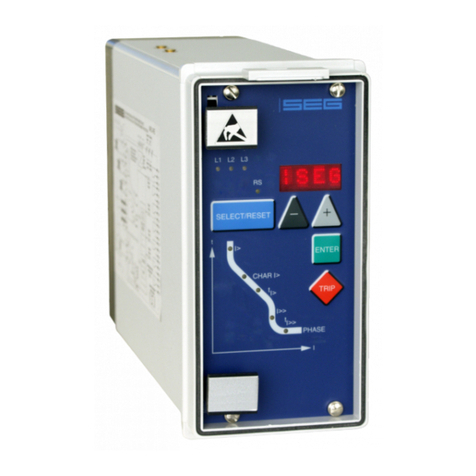
•Alphanumerical display (4 Digits)
•Push buttons for setting and other operations
•LEDs for measured value indication and setting
Fig. 3.4: Front plate XRI1-IR

TB XRI1-IR 02.00 E 7
3.2.2Display
Function Display shows Pressed push button Corresponding LED
Normal operation SEG
Measured operating values Actual measured values, <SELECT/RESET>
one time for each
L1, L2, L3
IP/IQwith regard to di-
rectional feature
Measuring range overflow max. <SELECT/RESET> L1, L2, L3
Setting values:
phase (I>; CHAR I>; tI>; I>>; tI>>)
Current settings
Trip delay
Characteristics
<SELECT/RESET>
one time for each
parameter
I >; CHAR I>; tI>; I>>;
tI>>; LED →←
Reset setting (only available at inverse
time characteristics)
0s / 60s <SELECT/RESET>
<+><->
I>; CHAR I>; tI>
Relay characteristic angle for pase cur-
rent directional feature
RCA in degree (°) <SELECT/RESET>
<+><->
LED →← (green)
Warning reverse direction
no warning
warning
NOWA
WBAK
<SELECT/RESET>
<+><->
LED →← (red) + I>
Switch failure protection tCBFP <SELECT/RESET> <+><->
Tripping protection
switch failure protection
CBFP After fault tripping
Nominal frequency f=50 / f=60 <SELECT/RESET><+><->
Switch-over LED flash
No LED flash
FLSH
NOFL
<SELECT/RESET>
<+><->
Blocking of function EXIT <+> until max. setting value LED of blocked
parameter
Slave address of serial interface 1 - 32 <SELECT/RESET>
<+><->
RS
Recorded fault data Tripping currents and other
fault data
<SELECT/RESET>
one time for each phase
L1, L2, L3, E
I>, I>>, IE>, IE>>, UE>
Save parameter? SAV? <ENTER>
Delete failure memory wait <-> <SELECT/RESET>
Enquiry failure memory FLT1; FLT2..... <-><+> L1, L2, L3, E
I>, I>>, IE>, IE>>,
Save parameter! SAV! <ENTER> for about 3 s
Software version First part (e.g. D01-)
Sec. part (e.g. 8.00)
<TRIP>
one time for each part
Manual trip TRI? <TRIP> three times
Inquire password PSW? <TRIP><ENTER>
Relay tripped TRIP <TRIP>
or after fault tripping
Secret password input XXXX <SELECT/RESET>
<+><-><ENTER>
System reset SEG <SELECT/RESET>
for about 3 s
Table 3.1: Possible indication messages on the display
3.2.3LEDs
The LEDs left from the display, L1, L2, L3, are partially
bi-colored, the green indicating measuring, and the
red fault indication.
XRI1-IR with directional feature have a LED (green- and
red arrow) for the directional display. At pickup/trip
and parameter setting the green LED lights up to indi-
cate the forward direction, the red LED indicates the
reverse direction.
The LED marked with letters RS lights up during setting
of the slave address of the device for serial data com-
munication.
The LEDs arranged at the characteristic points on the
setting curves support the comfortable setting menu se-
lection. In accordance with the display 5 LEDs for
phase fault overcurrent indicate the corresponding
menu point selected.

8 TB XRI1-IR 02.00 E
3.2.4Parameter settings (see chapter 6)
Relay-type XRI1-IR
I>
CHAR I>
tI>
0s / 60s 1)
I>>
tI>>
RCA
tCBFP
50/60 Hz
LED-Flash
RS485 / Slaveaddress
Table 3.2: Parameter values
1) Reset setting for inverse time characteristics in phase
current path
Additional parameters:
Relay-type XRI1-IR
Blocking mode
Relay parameterizing
Fault recorder
Table 3.3

TB XRI1-IR 02.00 E 9
4Working principle
4.1Analog circuits
The incoming currents from the main current transform-
ers on the protected object are converted to voltage
signals in proportion to the currents via the input trans-
formers and burden. The noise signals caused by in-
ductive and capacitive coupling are supressed by an
analog R-C filter circuit.
The analog voltage signals are fed to the A/D-
converter of the microprocessor and transformed to
digital signals through Sample- and Hold-circuits. The
analog signals are sampled at 50 Hz (60 Hz) with a
sampling frequency of 800 Hz (960 Hz), namely, a
sampling rate of 1.25 ms (1.04 ms) for every measur-
ing quantity. (16 scans per periode).
4.2Digital circuits
The essential part of the XRI1-IR relay is a powerful
microcontroller. All of the operations, from the analog
digital conversion to the relay trip decision, are carried
out by the microcontroller digitally. The relay program
is located in an EPROM (Electrically-Programmable-
Read-Only-Memory). With this program the CPU of the
microcontroller calculates the three phase currents and
ground current in order to detect a possible fault situa-
tion in the protected object.
For the calculation of the current value an efficient digi-
tal filter based on the Fourier Transformation (DFFT -
Discrete Fast Fourier Transformation) is applied to sup-
press high frequency harmonics and DC components
caused by fault-induced transients or other system dis-
turbances.
The calculated actual current values are compared
with the relay settings. If a phase current exceeds the
pickup value, an alarm is given and after the set trip
delay has elapsed, the corresponding trip relay is acti-
vated.
The relay setting values for all parameters are stored in
a parameter memory (EEPROM - Electrically Erasable
Programmable Read-only Memory), so that the actual
relay settings cannot be lost, even if the power supply
is interrupted.
The microprocessor is supervised by a built-in "watch-
dog" timer. In case of a failure the watchdog timer re-
sets the microprocessor and gives an alarm signal, via
the output relay "self supervision".
4.3Directional feature
A built-in directional element in XRI1-IR is available for
application to doubly infeeded lines or to ring net-
works.
The measuring principle for determining the direction is
based on phase angle measurement and therefore
also on coincidence time measurement between cur-
rent and voltage. Since the necessary phase voltage
for determining the direction is frequently not available
in the event of a fault, whichever line-to-line voltage fol-
lows the faulty phase by 90° is used as the reference
voltage for the phase current. The characteristic angle
at which the greatest measuring sensitivity is achieved
can be set to precede the reference voltage in the
range from 15° to 83°.
Figure 4.1: Relay characteristic angle
The TRIP region of the directional element is deter-
mined by rotating the phasor on the maximum sensitiv-
ity angle for ±90°, so that a reliable direction deci-
sion can be achieved in all faulty cases.
Figure 4.2: TRIP/NO-TRIP region for directional element in
XRI1-IR. In this case the advance direction is
defined as TRIP region and the reverse direction
as NO-TRIP region.

10 TB XRI1-IR 02.00 E
By means of accurate hardware design and by using
an efficient directional algorithm a high sensitivity for
the voltage sensing circuit and a high accuracy for
phase angle measurement are achieved so that a cor-
rect directional decision can be made even by close
three-phase faults.
As an addition, to avoid maloperations due to distur-
bances, at least 2 periods (40 ms at 50 Hz) are
evaluated.
For the MRI1-overcurrent relays with directional feature
different time delays or time multipliers can be set for
forward and backward faults (ref. to chapter 6.1.3
and 6.1.6).
If the trip delay for backward faults is set longer than
the one for forward faults, the protective relay works as
a "backup"-relay for the other lines on the same bus-
bar. This means that the relay can clear a fault in the
backward direction with a longer time delay in case
of refusal of the relay or the circuit breaker on the
faulted line.
If the trip delay for backward faults is set out of range
(on the display "EXIT"), the relay will not trip in case of
backward faults.
4.4Requirements on the main
current transformers
The current transformers have to be rated in such a
way, that a saturation should not occur within the fol-
lowing operating current ranges:
Independent time overcurrent function: K1 = 2
Inverse time overcurrent function: K1 = 20
High-set function: K1 = 1.2 - 1.5
K1 = Current factor related to set value, at which the
C.T. is not yet saturated
Moreover, the current transformers have to be rated
according to the maximum expected short circuit cur-
rent in the network or in the protected objects.
The low power consumption in the current circuit of
XRI1-IR, namely <0.2 VA, has a positive effect on the
selection of current transformers. It implies that, if an
electromechanical relay is replaced by XRI1-IR, a high
accuracy limit factor is automatically obtained by using
the same current transformer.

TB XRI1-IR 02.00 E 11
5General operations and
settings
For adjustment of the unit the transparent cover has to
be opened as illustrated. Do not use force! The trans-
parent cover has two inserts for labels.
Fig. 5.1: How to open the transparent cover
5.1Push buttons
Push buttons are used for calling up the parameters to
be processed, for selection of measuring parameters to
be indicated and for changing and storing the pa-
rameters.
The individual setting and measuring values can be se-
lected one after another by pressing push button
<SELECT/RESET>. This push button is also used for re-
setting the display by pressing approx. 3s.
As for an individual case (relay version D) the push but-
ton can also be operated when the front cover of the
relay is closed and sealed with lead.
Push buttons <+> <-> are used for in-/decrementing of
the parameter indicated on the display. They can be
pressed step-by-step or continuously.
After the selected parameter is set by the <+> <->
push button it may be stored using the <ENTER> push
button.
Through the push button <ENTER> the set value indi-
cated on the display will be transfered to the internal
parameter memory. An unintented or unauthorized
change of the selected parameter is avoided by
means of a password identification (see 5.4.2).
The <TRIP>-push button is used to test the output relay
circuits both for tripping and signalling. During normal
operation it is also interlocked by means of the pass-
word identification.

12 TB XRI1-IR 02.00 E
5.1.1Indication of measuring values
and fault data
Indication in faultless condition
In normal operation the display always shows |SEG.
After pressing the push button <SELECT/RESET> the
display switches cyclically to the next measuring value.
After the measuring values had been indicated the set-
ting parameters are displayed. Hereby the LEDs in the
upper section signalize which measured value is indi-
cated, the LEDs in the lower section signalize which
setting parameter is indicated on the display. Longer
actuating the push button resets the relay and the dis-
play changes into normal operation (|SEG).
Indication after pickup / tripping
All of the faults detected by the relay are indicated on
the front plate optically. Here not only the faults are
indicated but also the faulty phase(s) and the protec-
tion function in operation. At pickup the LEDs are flash-
ing, after tripping this changes to continuous light.
In tripped condition "TRIP" appears on the display and
the LEDs of the operating measuring data light up red
together with the LEDs of the tripping parameter. All
operating data, which were measured at the moment
of tripping, can now be called one after another by
pressing push button <SELECT/RESET>. If in this condi-
tion setting parameters are to be indicated, push but-
ton <ENTER> has to be pressed.
The graphic below shows again the difference be-
tween the different display modes.
6(/(&7!
6(/(&7!
6(/(&7!
(17(5!
_6(* 75,3
6(/(&7!
6(/(&7!
(17(5!
6(/(&7!
'LVSOD\DIWHUWULSSLQJ
'LVSOD\LQQRUPDORSHUDWLRQ
7ULSSLQJ
5(6(7!
0HDVXULQJGDWD
3DUDPHWHU 3DUDPHWHU )DLOXUHGDWD
Fig. 5.2: Switching over of the display in dependence of the operating mode

TB XRI1-IR 02.00 E 13
5.2Dip switches
Behind the front plate of the XRI-IR relay there is one
dip switch to preset the following functions:
•Password programming
•Output relay functions
The following table 5.1 shows the position and desig-
nation of the code jumpers:
5.2.1Function of the output relays
The alarm relays are activated according to the preset-
ting:
Dip switch 3 OFF:
All output relays will be reset automatically after the
fault has been cleared, (e.g. when the fault current is
interrupted).
Dip switch 3 ON:
All output relays remains activated and must be reset
after fault clearence.
•Manually: By pressing push button
<SELECT/RESET>
•External: By connecting aux. voltage to C2/C2L
or C2/C2H
•Via RS 485 interface
To let the parameter change take effect, the auxiliary
voltage has to be switched on and off again after the
dip switches are plugged or unplugged.
Dip
switches
Function Code
jumper position
Operation mode
1Password OFF Normal position
ON Password selection
2none
3Reset OFF Output relays will be reset automatically
ON Output relays will be reset manual/external/via software
4none
Tab. 5.1: Summary of coding possibilities

14 TB XRI1-IR 02.00 E
5.3Reset
Manual reset
By pressing push button <RESET/SELECT> for some
time (about 3 s).
External reset-input C2/C2L or C2/C2H
The external reset input has the same function as the
<SELECT/RESET> push button on the front plate. Con-
necting auxiliary voltage to this input, the unit can be
reset, provided that the fault is removed.
Software reset via serial interface RS 485
Software reset has the same function as push button
<SELECT/RESET>. Please refer to open data protocol
of RS 485 interface named RS485-PRO.
5.4Password
5.4.1Password programming
The XRI1-IR-relay is delivered with the preset password
"++++", it can be programmed new with dip
switch 1:
Switch on dip switch 1. After power on and pressing
any push button, the relay XRI1-IR inquires for a new
password. The text "PSW?" appears on the display.
The new password is entered by any combination of
the push buttons <SELECT> <-> <+> <ENTER>. After
the new password is given, the dip switch 1 must be
switched off.
5.4.2Using the password
Step by step, a new relay setting is made according
to the following sequence:
•After the present setting value is changed with
<+><-> push button, <ENTER> push button should
be pressed.
•A message "SAV?" appears on the display to inquire
if the new setting value is really wanted to be stored.
•After pressing the <ENTER> push button again,the
password will be inquired by means of the message
"PSW?" on the display.
•After the password is given correctly, which is
prompted by message "SAV!" on the display, the
new setting value can be stored by pressing the
<ENTER> push button for about 3 seconds.
•The new setting value for the selected parameter
appears on the display again.
A password consists of four push button operations.
The pressed push buttons and their sequences define
the password.
<SELECT/RESET> = S
<-> = -
<+> = +
<ENTER> = E
then a password "-E+S" means pressing push buttons
according to the follwing sequence:
<-> <ENTER> <+> <SELECT/RESET>
After the password is given correctly, parameter setting
is permitted for five minutes. This means: For a subse-
quent parameter setting, as long as it is made within
five minutes after the password input, a renewed
password input is not required. Moreover, the valid
period for parameter setting is automatically extended
to further 5 minutes after each new push button opera-
tion.
If no push button operation follows within the five min-
ute period after password input, the validity for pa-
rameter setting will be suspended.
For entering further parameters the password is then
called up again. During the validity for parameter set-
ting a new set value, after having acknowledged
"SAV" two times, is stored by just pressing push button
<ENTER> for some time.
As to parameter setting via RS 485 interface: see
open data protocol.

TB XRI1-IR 02.00 E 15
5.5Relay setting principle
By pressing push button <ENTER>, the parameter
menue can be called up. By pressing push button
<SELECT/RESET> the parameter to be set is reached.
The corresponding LED lights up. The actual set value
of the selected parameter is indicated on the display.
The indicated set value can then be changed by press-
ing push buttons <+><-> (in-/decrementing) see figure
5.2).
The selected set value is stored by pressing push but-
ton <ENTER> and by input of the authority code
(password) which means the adjustment of the unit is
only possible after the password had been put in. (see
5.4.2)
After a trip the push button <SELECT/RESET> is re-
served for the indication of fault data. Now new pa-
rameter setting by means of push button
<SELECT/RESET> is only possible by pressing
<ENTER> first.
5.5.1Setting of default parameters
Setting of the XRI1-IR default parameters can be done
as follows:
•switch off the auxiliary voltage supply
•press simultaneously push buttons <+><-> and
<SELECT/RESET> and
•switch on the auxiliary voltage supply again.
5.5.2Blocking the protection function
The blocking function of the XRI1-IR-relays can be set
according to requirement. When pressing push buttons
<ENTER> and <TRIP> at the same time the blocking
mode is entered.
5.6Display of software version and
test-TRIP
By pressing push button <TRIP> the first part of the
software version is displayed, the second part appears
when this push button is pressed again. When push
button <TRIP> is pressed repeatedly, the test trip rou-
tine starts.
By entering the password the display shows "TRI?". Af-
ter pressing <TRIP> again all output relays will be en-
ergized one after the other with a time delay of 1 s.
All relays stay energized until manual reset. The protec-
tion functions are not affected.
5.7Low/high range of functions
blocking and reset
All relays of the HIGH TECH LINE have a wide-range
power supply unit allowing to choose a suitable supply
voltage. The operating threshold of the blocking and
reset inputs, however, has to be defined by taking the
supply voltage into account. The following two diffe-
rent operating thresholds can be adjusted:
•Low-range treshold UON ≥10 V; UOFF ≤8 V
•High-range treshold UON ≥70 V; UOFF ≤60 V
Connection terminals
•Low-range blockage input terminal C1/C1L
•Low-range reset input terminal C2/C2L
•High-range blockage input terminal C1/C1H
•High-range reset input terminal C2/C2H

16 TB XRI1-IR 02.00 E
6Operations and settings
6.1Setting procedure
After push button <SELECT/RESET> has been pressed,
always the next measuring value is indicated. Firstly
the operating measuring values are indicated and then
the setting parameters. By pressing the <ENTER> push
button the setting values can directly be called up and
changed.
6.1.1Pickup current for phase
overcurrent element (I>)
The setting value for this parameter that appears on the
display is related to the nominal current (IN) of the re-
lay. This means: pickup current (Is) = displayed value x
nominal current (IN) e.g. displayed value = 1.25 then,
Is = 1.25 x IN.
6.1.2Time current characteristics for
phase overcurrent element
(CHAR I>)
By setting this parameter, one of the following 4 mes-
sages appears on the display:
DEFT - Definite Time
NINV - Normal Inverse (type A)
VINV - Very Inverse (type B)
EINV - Extremely Inverse (type C)
Anyone of these four characteristics can be chosen by
using <+> <-> push buttons, and can be stored by us-
ing <ENTER> push button.
6.1.3Trip delay or time multiplier for
phase overcurrent element (tI>)
Usually, after the characteristic is changed, the time
delay or the time multiplier should be changed accord-
ingly. In order to avoid an unsuitable arrangement of
relay modes due to carelessness of the operator, the
following precautions are taken:
After the characteristic setting, the setting process turns
to the time delay setting automatically. The LED tI> is
going to flash yellow to remind the operator to change
the time delay setting accordingly. After pressing the
<SELECT> push button, the present time delay setting
value is shown on the display. The new setting value
can then be changed by using <+> <-> push buttons.
If, through a new setting, another relay characteristic
other than the old one has been chosen (e.g. from
DEFT to NINV), but the time delay setting has not been
changed despite the warning from the flashing LED,
the relay will be set to the most sensitive time setting
value of the selected characteristics after five minutes
warning of flashing LED tI>. The most sensitive time set-
ting value means the fastest tripping for the selected re-
lay characteristic. When the time delay or the time
multiplier is set out of range (Text "EXIT" appears on the
display), the low set element of the overcurrent relay is
blocked. The "WARN"-relay will not be blocked.
For the XRI1-IR-version with directional feature, the dif-
ferent trip time delays or the time multipliers can be
chosen for forward and backward faults.
By setting the trip delay, the actual set value for for-
ward faults appears on the display first and the LED
under the arrows is alight green. It can be changed
with push button <+> <-> and then stored with push
button <ENTER>. After that, the actual trip delay (or
time multiplier) for backward faults appears on the dis-
play by pressing push button <SELECT> and the LED
under the arrows is alight red.
Usually this set value should be set longer than the one
for forward faults, so that the relay obtains its selectivity
during forward faults. If the time delays are set equally
for both forward and backward faults, the relay trips in
both cases with the same time delay, namely without
directional feature.
Note:
When selecting dependent tripping characteristics at
relays with directional phase current detection, atten-
tion must be paid that a clear directional detection will
be assured only after expiry of 40 ms.

TB XRI1-IR 02.00 E 17
6.1.4Reset setting for inverse time
tripping characteristics in the phase
current path
To ensure tripping, even with recurring fault pulses
shorter than the set trip delay, the reset mode for in-
verse time tripping characteristics can be switched
over. If the adjustment tRST is set at 60s, the tripping
time is only reset after 60s faultless condition. This
function is not available if tRST is set to 0. With fault
current cease the trip delay is reset immediately and
started again at recurring fault current.
6.1.5Current setting for high set element
(I>>)
The current setting value of this parameter appearing
on the display is related to the nominal current of the
relay.
This means: I>> = displayed value x IN.
When the current setting for high set element is set out
of range (on display appears "EXIT"), the high set ele-
ment of the overcurrent relay is blocked.
The high set element can be blocked via terminals
C1/C1L or C1/C1H if the corresponding blocking
parameter is set to bloc (refer to chapter 6.1.12).
6.1.6Trip delay for high set element (tI>>)
Independent from the chosen tripping characteristic for
I>, the high set element I>> has always a definite-time
tripping characteristic. An indication value in seconds
appears on the display.
The setting procedure for forward or backward faults,
described in chapter 6.1.3, is also valid for the trip-
ping time of the high set element.
6.1.7Relay characteristic angle RCA
The characteristic angle for directional feature in the
phase current path can be set by parameter RCA to
15°, 27°, 38°, 49°, 61°, 72° or 83°, leading to the
respective reference voltage (see chapter 4.3).
6.1.8Nominal frequency
The adapted FFT-algorithm requires the nominal fre-
quency as a parameter for correct digital sampling
and filtering of the input currents.
By pressing <SELECT> the display shows "f=50" or
"f=60". The desired nominal frequency can be ad-
justed by <+> or <-> and then stored with <ENTER>.
6.1.9Adjustment of the slave address
Pressing push buttons <+> and <-> the slave address-
can be set in range of 1-32.
6.1.10Circuit breaker failure protection
tCBFP
The CB failure protection is based on supervision of
phase currents during tripping events. Only after trip-
ping this protective function becomes active. The test
criterion is whether all phase currents are dropped to
<1% x INwithin the time tCBFP (Circuit Breaker Failure
Protection, adjustable between 0.1 - 1.6s). If not all of
the phase currents have dropped to <1% x INwithin
this time, CB failure is detected and the related relay
activated. The CB failure protection function is deacti-
vated again as soon as the phase currents have drop-
ped to <1% x IN within tCBFP
6.1.11Display of the activation storage
(FLSH/NOFL)
If after an activation the existing current drops again
below the pickup value, e.g. I>, without a trip has
been initiated, LED I> signals that an activation has
occured by flashing fast. The LED keeps flashing until it
is reset again (push button <RESET>). Flashing can be
suppressed when the parameter is set to NOFL.

18 TB XRI1-IR 02.00 E
6.1.12Blocking the protection functions
and assignment of the output
relays
Blocking the protection functions:
The blocking function of the XRI1-IR can be set accord-
ing to requirement. By applying the aux. voltage to
D8/E8, the functions chosen by the user are blocked.
Setting of the parameter should be done as follows:
•When pressing push buttons <ENTER> and <TRIP>
at the same time, message "BLOC" is displayed (i.e.
the respective function is blocked) or "NO_B"
(i.e. the respective function is not blocked). The LED
allocated to the first protection function I> lights red.
•By pressing push buttons <+> <-> the value dis-
played can be changed.
•The changed value is stored by pressing <ENTER>
and entering the password.
•By pressing the <SELECT/RESET> push button, any
further protection function which can be blocked is
displayed.
•Thereafter the blocking menu is left by pressing
<SELECT/RESET> again.
Function Display LED/Colour
I> Overcurrent
(Low set)
NO_B I> yellow
I>> Overcurrent
(High set)
BLOC I>> yellow
tCBFP Circuit breaker
failure protection
NO_B
Table 6.1: Default settings of blocking functions
Assignment of the output relays:
Unit XRI1-IR has five output relays. The fifth output relay
is provided as permanent alarm relay for self supervi-
sion is normally on. Output relays 1 - 4 are normally
off and can be assigned as alarm or tripping relays to
the current functions which can either be done by us-
ing the push buttons on the front plate or via serial in-
terface RS485. The assignment of the output relays is
similar to the setting of parameters, however, only in
the assignment mode. The assignment mode can be
reached only via the blocking mode.
By pressing push button <SELECT/RESET> in blocking
mode again, the assignment mode is selected.
The relays are assigned as follows: LEDs I>, I>>, IE>,
IE>> are two-coloured and light up green when the out-
put relays are assigned as alarm relays and red as
tripping relays.
In addition, the LED →← also lights up with each ad-
justment. Green means foreward and red backward
direction.
Definition:
Alarm relays are activated at pickup.
Tripping relays are only activated after elapse of the
tripping delay.
After the assignment mode has been activated, first
LED I> lights up green. Now one or several of the four
output relays can be assigned to current element I> as
alarm relays. At the same time the selected alarm re-
lays for frequency element 1 are indicated on the dis-
play. Indication "1_ _ _" means that output relay 1 is
assigned to this current element. When the display
shows "_ _ _ _", no alarm relay is assigned to this cur-
rent element. The assignment of output relays 1 - 4 to
the current elements can be changed by pressing <+>
and <-> push buttons. The selected assignment can be
stored by pressing push button <ENTER> and subse-
quent input of the password. By pressing push button
<SELECT/RESET>, LED I> lights up red. The output re-
lays can now be assigned to this current element as
tripping relays.
Relays 1 - 4 are selected in the same way as de-
scribed before. By repeatedly pressing of the
<SELECT/RESET> push button and assignment of the
relays all elements can be assigned separately to the
relays. The assignment mode can be terminated at any
time by pressing the <SELECT/RESET> push button for
some time (abt. 3 s).

TB XRI1-IR 02.00 E 19
Note:
•A form is attached to this description where the set-
ting requested by the customer can be filled-in. This
form is prepared for telefax transmission and can
be used for your own reference as well as for tele-
phone queries.
Relay function Output relays Display- Lighted LED
1234
indication
I> (V) alarm X _ 2 _ _ I>; →← green
tI> (V) tripping X 1 _ _ _ tI>; →← green
I>> (R) alarm X _ 2 _ _ I>>; →← red
tI> (R) tripping X 1 _ _ _ tI>>; →← red
I>> (V)IE> alarm X _ 2 _ _ IIE>; →← green
tI>> (V) tripping X 1 _ _ _ tIE>>; →← green
I>> (R)IE>> alarm X _ 2 _ _ IE>>; →← red
tI>> (R) tripping X 1 _ _ _ tI>>;→← red
Table 6.2: Example of assignment matrix of the output relay
(default settings).
(V) = foreward direction;
(R) = backward direction
This way, a tripping relay can be set for each activa-
tion and tripping direction.

20 TB XRI1-IR 02.00 E
6.2Setting value calculation
6.2.1Definite time overcurrent element
Low set element I>
The pickup current setting is determined by the load
capacity of the protected object and by the smallest
fault current within the operating range. The pickup
current is usually selected about 20% for power lines,
about 50% for transformers and motors above the
maximum expected load currents.
The delay of the trip signal is selected with considera-
tion to the demand on the selectivity according to sys-
tem time grading and overload capacity of the pro-
tected object.
High set element I>>
The high set element is normally set to act for near-by
faults. A very good protective reach can be achieved
if the impedance of the protected object results in a
well-defined fault current. In case of a line-transformer
combination the setting values of the high set element
can even be set for the fault inside the transformer.
The time delay for high set element is always inde-
pendent to the fault current.
6.2.2Inverse time overcurrent
element
Beside the selection of the time current characteristic
one set value each for the phase current path and
earth current path is adjusted.
Low set element I>
The pickup current is determined according to the
maximum expected load current. For example:
Current transformer ratio: 400/5A
Maximum expected load current: 300A
Overload coefficient: 1.2 (assumed)
Starting current setting:
Is = (300/400) x 1.2 = 0.9 x IN
Time multiplier setting
The time multiplier setting for inverse time overcurrent is
a scale factor for the selected characteristics. The
characteristics for two adjacent relays should have a
time interval of about 0.3 - 0.4 s.
High set element I>>
The high set current setting is set as a multiplier of the
nominal current. The time delay tI>> is always inde-
pendent to the fault current.
6.3Indication of measuring and fault
values
6.3.1Measuring values
The following measuring quantities can be indicated
on the display during normal service:
•Apparent current in phase 1 (LED L1 green)
•Active current in Phase 1 (LED L1 and IPyellow)
•Reactive current in Phase 1 (LED L1 and IQyellow)
•Apparent current in phase 2 (LED L2 green)
•Active current in Phase 2 (LED L2 and IPyellow)
•Reactive current in Phase 2 (LED L2 and IQyellow)
•Apparent current in phase 3 (LED L3 green)
•Active current in Phase 3 (LED L3 and IPyellow)
•Reactive current in Phase 3 (LED L3 and IQyellow)
6.3.2Indication of fault data
All faults detected by the relay are indicated on the
front plate optically. For this purpose, the four LEDs (L1,
L2, L3, E) and the four function LEDs (I>, I>>, IE>,
IE>> und →←) are equipped at XRI1-IR. If, for exam-
ple an overcurrent occurs, first the LEDs of the corre-
sponding phases will light up. LED I> lights up at the
same time. After tripping the LEDs are lit permanently.
Table of contents
Other Seg Relay manuals