Seg MRIK3 User manual

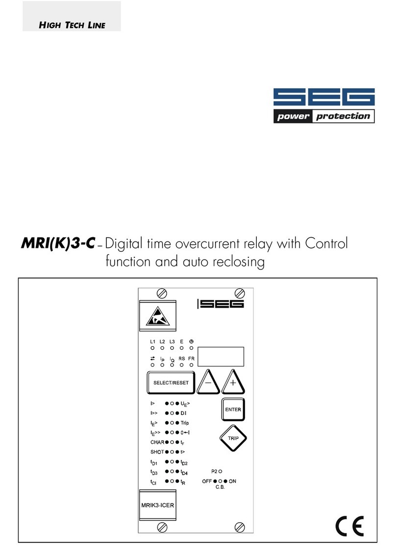
MRIK3 - Time overcurrent relay with auto reclosing relay

2 TB MRIK3 12.00 E
Contents
1 Introduction and application
2 Features and characteristics
3Design
3.1 Connections
3.1.1 Analog input circuits
3.1.2 AR Information input circuits
3.1.3 Blocking input
3.1.4 External reset input
3.1.5 Output relays of MRIK3 relays
3.1.6 Fault recorder
3.2 LEDs
3.2.1 Indication-LEDs
3.2.2 Setting-LEDs
3.3 Low/High range of signal inputs
4 Working principle
4.1 Analog circuits
4.2 Digital circuits
4.3 Status descriptions
4.3.1 "Inactive"
4.3.2 "Reclaim time" tR
4.3.3 "AR-ready"
4.3.4 "AR-starting" (dead time)
4.3.5 "AR-cycle" (auto reclosing)
4.3.6 "AR-blocked"
4.3.7 "Fast Trip Mode"
4.3.8 Blocking mode
4.3.9 Activating of AR
4.4 Description of the status transition
4.5 Functional sequence
4.5.1 Switching-on MRIK3
4.5.2 Circuit breaker manual closing
4.5.3 Circuit breaker manual open
4.5.4 Starting AR
4.5.5 Unsuccessful reclosing
4.5.6 Successful reclosing
4.5.7 Repeated reclosing
4.5.8 Supervision of the circuit breaker ready
information
4.5.9 External blocking
4.6 Time sequence diagrams of MRIK3
4.6.1 The unit is programmed for two shots,
successful AR at the second shot
4.6.2 The unit is programmed for two shots,
unsuccessful AR
4.6.3 Manual closing of the circuit breaker to
faulty lines
4.6.4 Unsuccessful AR
5 Operations and settings
5.1 Display
5.2 Setting procedure
5.3 Systemparameter
5.3.1 Display of measuring values as primary
quantities (Iprim phase)
5.3.2 Display of earth current as primary
quantity (Iprim earth)
5.3.3 Nominal frequency
5.3.4 Display of the activation storage
(FLSH/NOFL)
5.3.5 Parameterswitch/external triggering of
the fault recorder
5.4 Parameter protection
5.4.1 Pickup current for phase overcurrent
element (I>)
5.4.2 Time current characteristics for phase
overcurrent element (I> + CHAR)
5.4.3 Trip delay or time multiplier for phase
overcurrent element (tI>)
5.4.4 Reset setting for inverse time tripping
characteristics in the phase current path
5.4.5 Current setting for high set element (I>>)
5.4.6 Trip delay for high set element (tI>>)
5.4.7 Pickup current for earth fault element (IE>)
5.4.8 WARN/TRIP changeover
5.4.9 Time current characteristics for earth fault
element (CHAR IE)
5.4.10 Trip delay or time multiplier for earth fault
element (tIE>>)
5.4.11 Current setting for high set element of
earth fault supervision (IE>>)
5.4.12 Trip delay for high set element of earth
fault supervision (tIE>>)
5.4.13 Parameters auto reclosing Number of
AR-SHOTS
5.4.14 Fault time (tF)
5.4.15 Dead time (tD)
5.4.16 Close impulse time (tCI)
5.4.17 Reclaim time (tR)
5.4.18 Fault time activation
5.4.19 Block/Trip - time
5.4.20 Circuit breaker failure protection tCBFP
5.4.21 Adjustment of the slave address
5.4.22 Setting of Baud-rate (applies for Modbus
Protocol only)
5.4.23 Setting of parity (applies for Modbus
Protocol only)

TB MRIK3 12.00 E 3
5.5 Fault recorder
5.5.1 Number of the fault recordings
5.5.2 Adjustment of trigger occurences
5.5.3 Pre-trigger time (Tpre)
5.6 Adjustment of the clock
5.7 Additional functions
5.7.1 Blocking the protection functions,
assignment of the output relays and
AR - functions
5.8 Indication of measuring and fault values
5.8.1 Indication of measuring values
5.8.2 Unit of the measuring values displayed
5.8.3 Indication of fault data
5.9 Fault memory
5.10 Reset
5.10.1 Erasure of fault storage
6 Relay testing and commissioning
6.1 Power-On
6.2 Testing the output relays and LEDs
6.3 Checking the set values
6.4 Secondary injection test
6.4.1 Test equipment
6.4.2 Example of test circuit for MRIK3 relays
6.4.3 Checking the input circuits and measured
values
6.4.4 Checking the operating and resetting
values of the relay
6.4.5 Checking the relay operating time
6.4.6 Checking the high set element of the
relay
6.4.7 Checking the auto reclosing function
6.4.8 Checking the circuit breaker position
(A2/A7 and A2/A5)
6.4.9 Checking the AR-blocking input (A2/A3)
6.4.10 Checking the external blocking and reset
functions
6.4.11 Testing the external blocking with
Block/Trip function
6.4.12 Test of the CB failure protection
6.5 Primary injection test
6.6 Maintenance
7 Technical data
7.1 Measuring input circuits
7.2 Common data
7.3 Setting ranges and steps
7.3.1 Time overcurrent protection
7.3.2 Earth fault protection
7.3.3 Inverse time overcurrent protection relay
7.3.4 Inverse time characteristics
7.4 Parameter
7.5 Design standard
8 Order form

4 TB MRIK3 12.00 E
1Introduction and application
The MRlK1 digital multifunctional relay is a universal
time overcurrent and earth fault protection device with
integrated auto reclosing relay intended for use in me-
dium-voltage systems, either with an isolated/com-
pensated neutral point or for networks with a solidly
earthed/resistance-earthed neutral point.
In transmission line networks more than 70% of the oc-
curring faults are transient (electric arcs extinguish,
branches are falling on the overhead lines etc.)
With the application of the automatic reclosing (AR) to-
gether with protection relays, many electric arcs are ex-
tinguished through temporary interruption of the energy
supply.
Without utilizing the automatic reclosing (AR) power
supply interruptions would occur quite frequently.
Statistics have shown that yet part of the faults remain
after the first fast AR can be cleared with a longer 2nd
AR interval.
The digital multi-shot, three phase auto reclosing relay
MRIK3 fulfills these requirements for use on medium
voltage transmission or distribution systems, by
4-element AR with variable adjustable dead times.
Important:
For additional common data of all MR-relays please re-
fer to manual "MR - Digital Multifunctional relays".
2Features and characteristics
•Digital filtering of the measured values by using dis-
crete Fourier analysis to suppress the high frequence
harmonics and DC components induced by faults or
system operations,
•two parameter sets,
•selectable protective functions between:
definite time overcurrent relay or
inverse time overcurrent relay,
•selectable inverse time characteristics according to
IEC 255-4:
Normal Inverse (Type A)
Very Inverse (Type B)
Extremely Inverse (Type C
Special characteristics,
•reset setting for inverse time characteristics selectable,
•high set overcurrent unit with instantaneous or de-finite
time function,
•two-element (low and high set) overcurrent relay for
both phase and earth faults independent from each
other,
•circuit breaker failure protection,
•4-element AR with Fast-Trip Mode,
•adjustable timer for fault time, dead time, close im-
pulse time and reclaim time,
•external blocking and blocking release of AR,
•optical indications of the AR functional sequence and
the AR results,
•external control through optically isolated inputs,
•number of auto reclosings, adjustable from 1 to 4,
•display of measuring values as primary quantities,
•blocking e.g. of high set element (e.g. for selective
fault detection through minor overcurrent protection
units after unsuccessful AR),
•free assignment of output relays,
•free assignment of protective function for every reclos-
ing separately adjustable,
•blocking the protection function or Fast-Trip-tripping for
a selective switch off before and after each AR sepa-
rately adjustable,
•suppression of indication after an activation
(LED flash),
•storage of trip values and switching-off time (tCBFP) of 5
fault occurences (fail-safe of voltage),
•recording of up to eight fault occurences with time
stamp,
•serial data exchange via RS485 interface possible;
alternatively with SEG RS485 Pro-Open Data Protocol
or Modbus Protocol,
•display of date and time

TB MRIK3 12.00 E 5
3Design
3.1 Connections
Figure 3.1: Connections MRIK3-I
Figure 3.2: Connections MRIK3-IE

6 TB MRIK3 12.00 E
3.1.1 Analog input circuits
The protection unit receives the analog input signals of
the phase currents IL1 (B3-B4), IL2 (B5-B6), IL3 B7-B8)
and the current IE (B1-B2), each via separate input
transformers.
The constantly detected current measuring values are
galvanically decoupled, filtered and finally fed to the
analog/digital converter.
3.1.2 AR Information input circuits
With the aid of information inputs unit MRIK3 decides
whether and when auto-reclosing may take place:
Circuit breaker position (A7)
With input A7 the position of C.B. can be supervised.
When the circuit breaker is closed the auxiliary voltage
is connected to input A7.
Circuit breaker energy (e.g. motor-wound spring-
closed breakers) (A5)
Because the circuit breaker needs a certain time bet-
ween two reclosing-attempts in order to close again, the
ready signal of the C.B. (auxiliary voltage at A5) is
checked before a new auto reclosing takes place. (see
also para. 4.5.8)
External blocking input (A3)
The unit is blocked when applying voltage to A3.
Common point of the inputs (A2)
All listed inputs have a common connection point for
L- or N.
3.1.3 Blocking input
The protection functions adjusted before will be blocked
if an auxiliary voltage is applied to (terminals) D8/E8
(refer to chapter 5.7.1).
3.1.4 External reset input
Please refer to chapter 5.10.
3.1.5 Output relays of MRIK3 relays
Two relays are equipped with two change-over contacts
and three relays with each one change-over contact for
alarm. Apart from the relay for self-supervision, all pro-
tective functions can be optionally assigned:
•Relay 1: C1, D1, E1 and C2, D2, E2
•Relay 2: C3, D3, E3 and C4, D4, E4
•Relay 3: C5, D5, E5
•Relay 4: C6, D6, E6
•Relay 5: Self-supervision C7, D7, E7
All trip and alarm relays are working current relays, the
relay for self supervision is an idle current relay.
The output relays can be assigned to the tripping func-
tions as required.

TB MRIK3 12.00 E 7
3.1.6 Fault recorder
The MRIK3 has a fault value recorder which records the
measured analog values as instantaneous values.
The instantaneous values
iL1, iL2, iL3, iE, (iUe)*,
are scanned at a raster of 1.25 ms (at 50 Hz) and
1.041 ms (at 60 Hz) and saved in a cyclic buffer. It is
possible to store 1 - 8 fault occurences with a total re-
cording time of 16 s (with 50 Hz) and 13.33 s (with
60 Hz) per channel. (see chapter 5.5.1)
Storage division
Independent of the recording time, the entire storage
capacity can be divided into several cases of distur-
bance with a shorter recording time each. In addition,
the deletion behaviour of the fault recorder can be influ-
enced.
No writing over
If 2, 4 or 8 recordings are chosen, the complete mem-
ory is divided into the relevant number of partial seg-
ments. If this max. number of fault event has been ex-
ceeded, the fault recorder block any further recordings
in order to prevent that the stored data are written over.
After the data have been read and deleted, the re-
corder to ready again for further action.
Writing over
If 1, 3 or 7 recordings are chosen, the relevant number
of partial segments is reserved in the complete memory.
If the memory is full, a new recording will always write
over the oldest one.
The memory part of the fault recorder is designed as
circulating storage. In this example 7 fault records can
be stored (written over).
Figure 3.3: Division of the memory into 8 segments, for example
Memory space 6 to 4 is occupied.
Memory space 5 is currently being written in
Since memory spaces 6, 7 and 8 are occupied, this
example shows that the memory has been assigned
more than eight recordings. This means that No. 6 is
the oldest fault recording and No. 4 the most recent
one.
trigger occurence
recording duration
Tpre
[s]
Figure 3.4: Basic set-up of the fault recorder
Each memory segment has a specified storage time
which permits setting of a time prior to the trigger event.
Via the interface RS485 the data can be read and
processed by means of a PC with HTL/PL-Soft4. The
data is graphically edited and displayed. Binary tracks
are recorded as well, e.g. activation and trip.

8 TB MRIK3 12.00 E
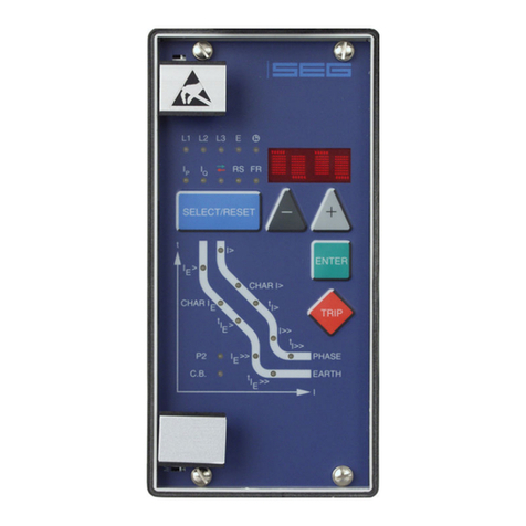
Figure 3.5: Front panel MRIK3-I
Figure 3.6: Front panel MRIK3-IE
3.2 LEDs
Five pushbuttons for control and/or adjustment and up
to 21 LEDs are on the front plate of unit MRIK3. The
LEDs on the left side of the display indicate the status,
fault messages and AR- results. The function of the re-
spective LED is indicated by the legend above the LED.
The LEDs on the left side beneath the <SELECT/RESET>
pushbutton are provided for adjustments, their functions
are shown with a legend on the right or left side of the
LED.
3.2.1 Indication-LEDs
L1, L2, L3, E: Phase or earth current
O→I green: AR successful; red: AR unsuccessful
OK: AR ready (Does not light: AR inactive)
AR: AR status
CB: Circuit breaker on
RS: Setting slave address
3.2.2 Setting-LEDs
P2: Two parameter sets
I>: green, pickup value phase current
tI>: red, trip delay / time multiplier
phase current
I>>: green pickup value phase current
tI>>: red, trip delay phase current
IE>: green, pickup value earth current
tIE>: red, trip delay / time multiplier earth
current
IE>>: geen, pickup value earth current
tIE>>: red, trip delay earth current
CHAR green, tripping characteristic phase
and earth path
tRST: red, reset time phase and earth
SHOT: green, number of the reclosing attempts
tF: red, Fault time
tD1: green, Dead time for the first reclosing
attempt
tD2: red, Dead time for the second reclosing
attempt
tD3: green, Dead time for the third reclosing
attempt
tD4: red, Dead time for the fourth reclosing
attempt
tC1: green, Close impulse time
tR: red, Reclaim time
C.B.: Time delay of circuit breaker failure
protection

TB MRIK3 12.00 E 9
3.3 Low/High range of signal inputs
The MRIK3 has a wide-range power supply unit allow-
ing to choose a suitable supply voltage. The operating
threshold of the signal inputs, however, has to be de-
fined by taking the supply voltage into account. The fol-
lowing two different operating thresholds can be ad-
justed:
•Low-range treshold UAN ≥10 V; UAB ≤8 V
(code jumper plugged)
•High-range treshold UAN ≥70 V; UAB ≤60 V
(code jumper not plugged)
Figure 3.7: Code jumper for MRIK3 relays

10 TB MRIK3 12.00 E
4Working principle
4.1 Analog circuits
The incoming currents from the main current transformers
on the protected object are converted to voltage signals
in proportion to the currents via the input transformers
and burden. The noise signals caused by inductive and
capacitive coupling are supressed by an analog R-C fil-
ter circuit.
The analog voltage signals are fed to the A/D-converter
of the microprocessor and transformed to digital signals
through Sample- and Hold-circuits. The analog signals
are sampled at 50 Hz (60 Hz) with a sampling fre-
quency of 800 Hz (960 Hz), namely, a sampling rate
of 1.25 ms (1.04 ms) for every measuring quantity. (16
scans per periode).
4.2 Digital circuits
The essential part of the MRIK3 relay is a powerful mi-
crocontroller. All of the operations, from the analog digi-
tal conversion to the relay trip decision, are carried out
by the microcontroller digitally. The relay program is lo-
cated in an EPROM (Electrically-Programmable-Read-
Only-Memory). With this program the CPU of the mi-
crocontroller calculates the three phase currents and
ground current in order to detect a possible fault situa-
tion in the protected object.
For the calculation of the current value an efficient digi-
tal filter based on the Fourier Transformation (DFFT - Dis-
crete Fast Fourier Transformation) is applied to suppress
high frequency harmonics and DC components caused
by fault-induced transients or other system disturbances.
The calculated actual current values are compared with
the relay settings. If a phase current exceeds the pickup
value, an alarm is given and after the set trip delay has
elapsed, the corresponding trip relay is activated.
The relay setting values for all parameters are stored in
a parameter memory (EEPROM - Electrically Erasable
Programmable Read-only Memory), so that the actual re-
lay settings cannot be lost, even if the power supply is
interrupted.
The microprocessor is supervised by a built-in "watch-
dog" timer. In case of a failure the watchdog timer re-
sets the microprocessor and gives an alarm signal, via
the output relay "self supervision".
4.3 Status descriptions
Reaction to protection events is possible at any time un-
less blocking is expressly desired (refer to 3.1.3). In the
inactive and blocked state auto reclosing is not possi-
ble.
For the explanation of the functional sequence the fol-
lowing six status transitions are defined.
4.3.1 "Inactive"
The relay is in "inactive" status if one of the following
conditions is fulfilled:
•The circuit breaker is in position "OFF",
•the unit is in "blocked" status,
•the unit is not in "starting/cycle" status
4.3.2 "Reclaim time" tR
The relay is in "reclaim time" status (tR) when the reclaim
time
•has not yet expired or
•not interrupted by other incidents.
4.3.3 "AR-ready"
The relay is in position "AR-ready" status when the fol-
lowing conditions are fulfilled:
•The circuit breaker is in position "ON",
•the reclaim time has expired,
•the unit is not in "blocked" status,
•the unit is not in "starting cycle" status.
Only in "AR-ready" status a reaction of the AR-unit to the
protection incidents is possible!
4.3.4 "AR-starting" (dead time)
In "AR-starting" status the start conditions for an auto-
matic reclosing by means of the protection commands
and the circuit breaker position are checked.

TB MRIK3 12.00 E 11
4.3.5 "AR-cycle" (auto reclosing)
The reclosing commands are carried out in "AR-cycle"
status by means of the conditions and the presetting.
The results (AR successful or unsuccessful) are evaluated
accordingly.
4.3.6 "AR-blocked"
Unit MRIK3 changes immediately to "AR-blocked" status
when an external or internal blocking signal
(A2-A3) exists. No auto reclosing is possible in "AR-
blocked" status.
4.3.7 "Fast Trip Mode"
By way of the function "Assignment of the AR functions"
it is possible to activate or deactivate a Fast Trip func-
tion for each AR stage and for each protective function.
This is applicable for tripping before the 1st AR up to
tripping after the last AR.
4.3.8 Blocking mode
By way of the function "Assignment of the AR functions"
it is possible to activate or deactivate a protection func-
tion for each AR stage. This is applicable for tripping
before the 1st AR up to tripping after the last AR.
4.3.9 Activating of AR
Prior to every AR it is possible to stipulate which kind of
tripping (I> or I>>, etc.) will lead to automatic reclosing.
This can be separately fixed for each AR stage.

12 TB MRIK3 12.00 E
4.4 Description of the status transition
AR-status transition matrix
to
from
inactive reclaim time ready starting
(dead time)
cycle (auto
reclosing)
blocked
inactive C.B. manual
ON
external
blocking
signal
reclaim time reclaim time
expired
external
blocking
signal
ready C.B. OFF protection ener-
gized and/or
tripped and C.B.-
energy OK
external
blocking
signal
starting starting
conditions not
fulfilled
start signal
interrupted
start condi-
tions fulfilled
(fault time,
C.B. OFF
etc.)
external
blocking
signal
cycle AR takes place external or
internal
blocking
signal
blocked external
reset of
blocking
Table 4.1: No status transition possible
From Table 4.1 you can detect what status transitions of
MRIK3 are possible. When the unit is for instance in
"cycle" status (see also para. 4.3) only two status transi-
tions are possible:
•status transition to "ready"-status when the auto reclos-
ing takes place
•status transition to "blocked" status by external or inter-
nal blocking.
The grey shaded sections indicate that no transition is
possible.
4.5 Functional sequence
4.5.1 Switching-on MRIK3
Is the C.B. to be supervised in OFF position while
“switching ON” the MRIK3, the unit changes into "inac-
tive" status when applying the auxiliary voltage. The LED
"CB" on the front plate remains dark. The unit is not
ready for auto reclosing. If, however, the C.B. is in
“ON” position when applying the auxiliary voltage, the
unit changes into "reclaim time"-status and remains
blocked during this period (from 1 s to 300 s adjustable).
This is indicated at the unit by LED tR. After expiration of
the reclaim time the unit changes to "ready" status and is
then ready for auto reclosing. LED "CB" signalizes this
status.
In case unit MRIK3 is in "blocked" status before auxiliary
voltage failure occurred, this condition remains also af-
ter recurrence of auxiliary voltage.
The LED CB shows the position of the C.B.

TB MRIK3 12.00 E 13
4.5.2 Circuit breaker manual closing
If the circuit breaker is closed manually to a faultless
line, first the unit remains blocked during the reclaim
time (adjustable 1 - 300 s) and then changes to "ready"
status. If the circuit breaker is closed manually to a faulty
line (e.g. short circuit), no AR follows. Unit MRIK3 re-
mains in "inactive" status after protection tripping. This is
indicated on the display by „MANU“.
4.5.3 Circuit breaker manual open
When switching off the circuit breaker manually the unit
changes at once without time delay from "ready" status
into "inactive" status. Auto reclosing is not possible.
The LED CB extinguishes.
4.5.4 Starting AR
When the information "protection energized" and "pro-
tection tripping" is applied, the unit changes from
"ready" status to "starting" status. The LED "AR" lights up.
The "starting" status begins with the start of a fault timer
(tF from 0.1 s to 2.0 s adjustable). The LED tF lights up
red. A tripping timer (set at 0.2 s) is started when the
mains protection tripping command takes place before
expiration of the set fault time. (C.B. must be tripped
within this time). The "start conditions not fulfilled" is
evaluated and the MRIK3 is locked for the duration of
the reclaim time when there is a time difference be-
tween mains protection-energized and tripping, which is
larger than the set "fault time". The LED tF flashes red. If
the OFF-signal of the C.B. appears before expiration of
the tripping timer, it is evaluated as "start condition ful-
filled" and the unit changes over to "cycle" status. The
LED tF extinguishes. If the OFF-signal does not appear,
however, before expiration of the tripping timer, it will
be evaluated as "start condition not fulfilled" and the unit
changes to „inactive“ status. The LED CB flashes and the
Display shows „CB??“.
Tripping timer: Time from the beginning of the tripping
command until receiving of the C.B. check-back signal.
4.5.5 Unsuccessful reclosing
After the start condition has been fulfilled the unit
changes to "starting" status. Now the dead time tD is
started. The corresponding LED flashes. Unit MRIK3 can
be programmed for reclosing of one to four times. For
each reclosing a dead time has to be set (tD1 to tD4).
When the dead time has expired and also the other re-
closing conditions have been fulfilled, the reclosing
command is given to the circuit breaker. The reclosing
command remains either as long as the ON-signal from
the circuit breaker appears or the close-impuls-timer (tCL)
has expired.
The LED tCL lights up for the duration of the close im-
pulse. When the CB-ON message occurs, the LED tCL ex-
tinguishes. After expiration of the ON impulse timer the
LED starts flashing and the display shows "CB??"
In the last case a failure of the circuit breaker is sub-
jected. With the beginning of the reclosing command
the reclaim timer is started. When a new “OFF-signal”
of the circuit breaker appears within the reclaim time
and after the last permissible AR, an unsuccessful reclos-
ing will be detected. The LED 0→I lights up red and the
display shows „OPEN“. Then the unit quits the "cycle"
status and changes to the "inactive" status. Simultane-
ously a relay can be activated which indicates unsuc-
cessful auto reclosing.
4.5.6 Successful reclosing
If there is no “OFF-signal” of the circuit breaker and no
protection tripping within the reclaim time a successful
reclosing will be detected.
During the reclaim time the display shows „CLOS“ and
the LED 0→I lights up green.
The unit now quits the "cycle" status, changes over into
the "ready" status and is ready for the next reclosing.
The LED AR extinguishes and the CB LED lights up. The
display shows „ISEG“.
4.5.7 Repeated reclosing
Is the MRIK3 programmed for more than single reclos-
ing a further dead time is started after a new “OFF-
signal” from the circuit breaker has appeared. After ex-
piration of this dead time a new reclosing command fol-
lows.

14 TB MRIK3 12.00 E
4.5.8 Supervision of the circuit breaker
ready information
Because the supervising unit of the circuit breaker en-
ergy store operates often after the first fast switch off
(see also para. 3.1.2), the signal "C.B. not AR-ready" is
not evaluated anymore after an introduced reclosing.
The C.B. ready information is checked before an intro-
duced AR for further ARs. There will be a reclosing
when the "circuit breaker ready" had been given before
the begin of the reclosing cycle. If not, the LED CB
flashes and the display shows „S/E?“.
4.5.9 External blocking
The AR-relay is blocked if the the external AR-block input
is activated.
When the reclosing shot is set to „EXIT“, the MRIK3 can
also be blocked at site. (see chapter 5.4.13)

TB MRIK3 12.00 E 15
4.6 Time sequence diagrams of MRIK3
Legend:
4.6.1 The unit is programmed for two shots, successful AR at the second shot
Figure 4.1: Two shots, second AR successful
In case of a short circuit an energizing follows with sub-
sequent tripping of the protection relay. The circuit
breaker is switched off and the short circuit is cleared.
After expiration of the dead time tD1 unit MRIK3 gives
the reclosing command to the circuit breaker.
If the fault still exists the protection relay trips again and
the above mentioned procedure is repeated as long un-
til either the fault was removed (here after the second
reclosing) or the number of the set SHOTs is reached.
4.6.2 The unit is programmed for two shots, unsuccessful AR
Figure 4.2: Two shots, AR unsuccessful
Here the time sequence as described in para. 4.6.1. The second reclosing shot is however unsuccessful.

16 TB MRIK3 12.00 E
4.6.3 Manual closing of the circuit breaker to faulty lines
Short
circuit
Protection
energized
Protection
tripped
Circuit breaker
Switch on
command
Manual on Protection tripped
Figure 4.3: Manual closing of the C.B. to faulty lines
Unit MRIK3 is in "inactive" status when the circuit
breaker is switched off. When the C.B. is manually
closed the reclaim time is started. In case there is a
faulty line the C.B. is switched off by mains protection
of the relay. After elapse of the reclaim time unit MRIK3
changes over to "inactive" status.
4.6.4 Unsuccessful AR
Figure 4.4: Unsuccessful AR
The sequence diagram illustrates the various possibilities
of an unsuccessful AR.

TB MRIK3 12.00 E 17
5Operations and settings
5.1 Display
Function Display shows Pressed push button Corresponding LED
Normal operation SEG
Measured operating values Actual measured values <SELECT/RESET>
one time for each value
L1, L2, L3, E
Measuring range overflow max. <SELECT/RESET> L1, L2, L3, E
Setting values:
Phase (I>; CHAR I>; tI>; I>>; tI>>)
Earth (IE>; CHAR IE; tIE>; IE>>; tIE>>)
Current settings
Trip delay
Characteristics
<SELECT/RESET>
one time for each
parameter
I >; CHAR I>; tI>; I>>; tI>>;
IE>;CHAR IE; tIE> ;IE>> ; tIE>>;
Parameter switch/external triggering of
the fault recorder
SET1, SET2, B_S2,
R_S2, B_FR, R_FR,
S2_FR
<+> <->
<SELECT/RESET>
P2
Switchable LED-Flash
None LED-Flash
FLSH
NOFL
<SELECT/RESET>
<+><->
Characteristics DEFT, NINV, VINV,
EINV, LINV, RINV
<+> <->
<SELECT/RESET>
CHAR I>
Characteristics DEFT, NINV, VINV,
EINV, LINV, RINV,
RXIDG
<+> <->
<SELECT/RESET>
CHAR IE>
Reset setting (only available for inverse
time characteristics)
0 s / 60 s <SELECT/RESET>
<+><->
I> + tRST
IE> + tRST
Warning or tripping at earth fault
measuring
trip/warn <SELECT/RESET>
<+><->
IE>
Setting values AWE:
Number of auto reclosing attempts
Fault time
Dead time for 1. - 4. auto reclosing attempt
Close impulse time
Fault time activation
Reclaim time
Fast trip mode
setting value in seconds
1ST/ALL
setting value in seconds
1ST/LAST/EXIT
<SELECT/RESET>
<+><-> one time for each
value
SHOT
tFred
tD1, tD2, tD3, tD4
tCI green
tI>; I>; I>>; IE>; IE>>
tRred
I>> + SHOT
Block/Trip-time setting value in seconds <SELECT/RESET><+><-> I>, I>>, tI>, tI>>, green
Time delay of circuit breaker failure pro-
tection tCBFP
setting value in seconds <SELECT/RESET>
<+><->
CB
Blocking of function EXIT <+> until max. setting
value
LED of blocked
parameter
Nominal frequency f=50 / f=60 <SELECT/RESET><+><->
Slave address of serial interface 1-32 <SELECT/RESET><+><-> RS
Baud-Rate 1) 1200-9600 <SELECT/RESET><+><-> RS
Parity-Check 1) even odd no <SELECT/RESET><+><-> RS
Recorded fault data Tripping currents
C.B. tripping time
max. pickup time
<SELECT/RESET>
one time for each phase,
<+><-> for older fault re-
cording
L1, L2, L3, E
I>, I>>, IE>, IE>>
CB
Circuit breaker defect CB?? CB blinking
Auto reclosing successful
Auto reclosing unsuccessful
CLOS
OPEN
0→1 green
0→1 red
Auto reclosing locked-out BLOC
After dead time reclosing condition
not fulfilled
S/E? 0→1 red
CB blinking
Circuit breaker was manually switched on MANU
Circuit breaker failure protection CBFP CB blinking
Display if AR is unsuccessful 0→1 red
Trigger signal for the fault recorder TEST, P_UP, A_PI, TRIP <SELECT/RESET> <+><-> FR
Number of fault occurences S = 2, S = 4, S = 8 <SELECT/RESET> <+><-> FR
1) only Modbus

18 TB MRIK3 12.00 E
Function Display shows Pressed push button Corresponding LED
Display of date and time Y = 99, M = 10, D = 1,
h = 12, m = 2, s = 12
<SELECT/RESET> <+><-> !
Change obver the blocking function PR_B, TR_B <ENTER> und <TRIP>;
<+> <->
I>, I>>, IE>, IE>> oder tI>,
tI>>, tIE>, tIE>>
Blocking the protection function BLOC, NO_B <+> <->
<SELECT/RESET>
I>, I>>, IE>, IE>>
AR approved YES/NO <+> <->
<SELECT/RESET>
AR + I>
AR + I>>
AR + IE>
AR + IE>>
Running with
tD1, tD2, tD3, tD4
Protection steps blocked BLOC <+> <->
<SELECT/RESET>
I>
I>>
Normal trip time TIME IE>
IE>>
Fast trip FAST Running with
tD1, tD2, tD3, tD4
Save parameter? SAV? <ENTER>
Save parameter! SAV! <ENTER> for about 3 s
Software version First part (e.g. A00-)
Sec. part (e.g. 4.01)
<TRIP>
one time for each part
Manual trip TRI? <TRIP> 3 times
Inquire password PSW? <SELECT/RESET>
<+><-><ENTER>
Relay tripped TRIP <TRIP>
or after fault tripping
Secret password input XXXX <SELECT/RESET>
<+><-><ENTER>
Switch-over LED flash
No LED flash
FLSH
NOFL
<SELECT/RESET>
<+><->
Enquiry failure memory FLT1; FLT2..... <-><+>
Delete failure memory wait <-> <SELECT/RESET>
System reset SEG <SELECT/RESET>
for about 3 s
Table 5.1: Possible indication messages on the display

TB MRIK3 12.00 E 19
5.2 Setting procedure
After push button <SELECT/RESET> has been pressed,
always the next measuring value is indicated. Firstly the
operating measuring values are indicated and then the
setting parameters. By pressing the <ENTER> push but-
ton the setting values can directly be called up and
changed.
5.3 Systemparameter
5.3.1 Display of measuring values as
primary quantities (Iprim phase)
With this parameter it is possible to show the indication
as primary measuring value. For this purpose the pa-
rameter must be set to be equal with the rated primary
CT current. If the parameter is set to "sec", the measur-
ing value is shown as a multiple of the rated secondary
CT current.
Example:
The current transformer used is of 1500/5 A. The flow-
ing current is 1380 A. The parameter is set to 1500 A
and on the display "1380 A" are shown. If the parame-
ter is set to "sec", the value shown on the display is
"0.92" x In.
Note:
The pick-up value is set to a multiple of the rated secon-
dary CT current.
5.3.2 Display of earth current as primary
quantity (Iprim earth)
The parameter of this function is to be set in the same
way as that described under 5.3.1. If the parameter is
not set to "sec", to relay types MRI3-X and MRI3-XR it
applies too, that the measuring value is shown as pri-
mary current in ampere. Apart from that the indication
refers to % of IN.
5.3.3 Nominal frequency
The adapted FFT-algorithm requires the nominal fre-
quency as a parameter for correct digital sampling and
filtering of the input currents.
By pressing <SELECT> the display shows "f=50" or
"f=60". The desired nominal frequency can be adjusted
by <+> or <-> and then stored with <ENTER>.
5.3.4 Display of the activation storage
(FLSH/NOFL)
If after an activation the existing current drops again be-
low the pickup value, e.g. I>, without a trip has been
initiated, LED I> signals that an activation has occured
by flashing fast. The LED keeps flashing until it is reset
again (push button <RESET>). Flashing can be sup-
pressed when the parameter is set to NOFL.
5.3.5 Parameterswitch/external
triggering of the fault recorder
By means of the parameter-change-over switches it is
possible to activate two different parameter sets. Switch-
ing over of the parameter sets can either be done by
means of software or via the external inputs RESET or
blocking input. Alternatively, the external inputs can be
used for Reset or blocking of the triggering of the fault
recorder.
Software-
parameter
Blocking input
used as
RESET input
used as
SET1 Blocking input RESET input
SET2 Blocking input RESET input
B_S2 Parameter switch RESET input
R_S2 Blocking input Parameter switch
B_FR External triggering
of the fault re-
corder
RESET input
R_FR Blocking input External triggering
of the fault re-
corder
S2_FR Parameter switch External triggering
of the fault re-
corder
With the settings SET1 or SET2 the parameter set is ac-
tivated by software. Terminals C8/D8 and D8/E8 are
then available as external reset input or blocking input.
With the setting B_S2 the blocking input (D8, E8) is
used as parameter-set change-over switch. With the set-
ting R_S2 the reset input (D8, E8) is used as parameter-
set change-over switch. With the setting B_FR the fault
recorder is activated immediately by using the blocking
input. On the front plate the LED FR will then light up for
the duration of the recording. With the setting R_FR the
fault recorder is activated via the reset input. With the
setting S2_FR parameter set 2 can be activated via the
blocking input and/or the fault recorder via the reset in-
put.
The relevant function is then activated by applying the
auxiliary voltage to one of the external inputs.

20 TB MRIK3 12.00 E
Important note:
When functioning as parameter change over facility,
the external input RESET is not available for resetting.
When using the external input BLOCKING the protec-
tion functions must be deactivated by software blocking
separately (refer to chapter 5.7.1).
5.4 Parameter protection
5.4.1 Pickup current for phase
overcurrent element (I>)
The setting value for this parameter that appears on the
display is related to the nominal current (IN) of the relay.
This means: pickup current (Is) = displayed value x
nominal current (IN) e.g. displayed value = 1.25 then, Is
= 1.25 x IN.
5.4.2 Time current characteristics for
phase overcurrent element
(I> + CHAR)
By setting this parameter, one of the following 6 mes-
sages appears on the display:
DEFT - Definite Time (Type A)
NINV - Normal Inverse (Type B)
VINV - Very Inverse (Type C)
EINV - Extremely Inverse
LINV - Long Time Inverse
RINV - RI - Inverse
Anyone of these four characteristics can be chosen by
using <+> <->-push buttons, and can be stored by us-
ing <ENTER>-push button.
5.4.3 Trip delay or time multiplier for
phase overcurrent element (tI>)
Usually, after the tripping characteristic is changed, the
time delay or the time multiplier should be changed ac-
cordingly. In order to avoid an unsuitable arrangement
of relay modes due to carelessness of the operator, the
following precautions are taken:
After the change of the characteristic setting, the setting
process turns to the time delay setting automatically. The
LED tI> is going to flash yellow to remind the operator to
change the time delay setting accordingly. After press-
ing the <SELECT>-push button, the present time delay
setting value is shown on the display. The new setting
value can then be changed by using <+> <-> -push but-
tons.
If, through a new setting, another relay characteristic
other than the old one has been chosen (e.g. from DEFT
to NINV), but the time delay setting has not been
changed despite the warning from the flashing LED, the
relay will be set to the most sensitive time setting value
of the selected characteristics after five minutes warning
of flashing LED tI>. The most sensitive time setting value
means the fastest tripping for the selected relay charac-
teristic. When the time delay or the time multiplier is set
out of range (Text "EXIT" appears on the display), the
low set element of the overcurrent relay is blocked. The
"WARN"-relay will not be blocked.
5.4.4 Reset setting for inverse time
tripping characteristics in the phase
current path
To ensure tripping, even with recurring fault pulses
shorter than the set trip delay, the reset mode for all
tripping characteristics can be switched over. If the ad-
justment RST is set at 60 s, the tripping time is only re-
set after 60 s faultless condition. This function is not
available if RST is set to 0. With interruption of the fault
current the trip delay is reset immediately and started
again at recurring fault current.
5.4.5 Current setting for high set element
(I>>)
The current setting value of this parameter appearing on
the display is related to the nominal current of the relay.
This means: I>> = displayed value x IN.
When the current setting for high set element is set out
of range (on display appears "EXIT"), the high set ele-
ment of the overcurrent relay is blocked.
The high set element can be blocked via terminals
E8/D8 if the corresponding blocking parameter is set to
BLOC (refer to 5.7.1).
Table of contents
Other Seg Relay manuals

Seg
Seg MRM3 User manual

Seg
Seg XRI1-IR User manual

Seg
Seg DiggiMEC User manual

Seg
Seg HighTECH Line MRI1IU User manual

Seg
Seg High Tech MRI3-ITE User manual

Seg
Seg HighTECH MRU3-2 User manual

Seg
Seg MRM3 User manual

Seg
Seg HighTECH Line User manual

Seg
Seg HighTECH Line MRN3-3 User manual

Seg
Seg MRN3 User manual
Popular Relay manuals by other brands

Westinghouse
Westinghouse BL-1 Installation operating & maintenance manual

Microelettrica Scientifica
Microelettrica Scientifica MC2-30V Operation manual

Allen-Bradley
Allen-Bradley Guardmaster MINOTAUR MSR121RT installation instructions

Veko
Veko MD-L-R quick start guide

GE
GE UR Series L90 instruction manual

Astrel Group
Astrel Group rialto installation manual