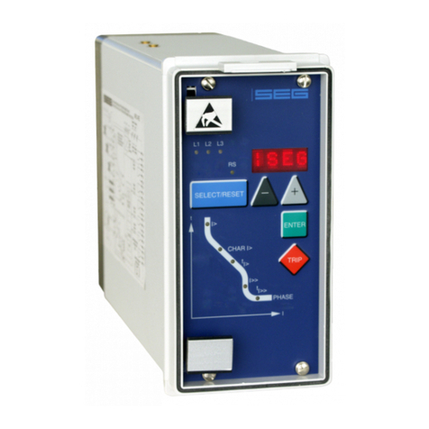
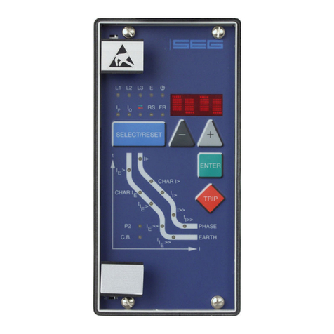
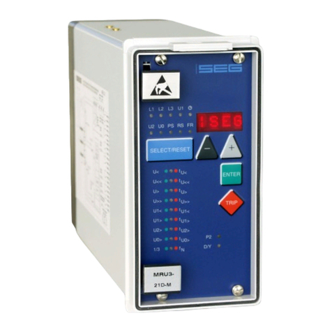
Seg XRW1-4 User manual

XRW1-4 -Mains decoupling relay for wind power systems

2TB XRW1-4 04.01 E
Contents
1 Introduction and application
2 Features and characteristics
3Design
3.1 Connections
3.1.1 Analog input circuits
3.1.2 Blocking input
3.1.3 Reset input
3.1.4 Low/High range of functions
blocking and reset
3.1.5 Output relays
3.1.6 Data communication
3.2 Front plate
3.2.1 Indication- and operation elements
3.2.2 Display
3.2.3 LEDs
3.2.4 Front plate XRW1-4
3.2.5 Parameter settings
4 Working principle
4.1 Analog circuits
4.2 Digital circuits
4.3 Voltage supervision
4.3.1 Selection of star or delta connection
4.4 Principle of frequency supervision
4.5 Measuring of frequency gradient
4.6 Voltage threshold value for frequency
measuring
4.7 Blocking function
5 Operation and setting
5.1 Push buttons
5.1.1 Indication of measuring values and
fault data
5.2 DIP switches
5.2.1 Function of the output relays
5.3 Reset
5.4 Password
5.4.1 Password programming
5.4.2 Using the password
5.5 Relay setting principle
5.5.1 Setting of default parameters
5.5.2 Blocking the protection functions
5.6 Display of software version and
test-TRIP
5.7 Low/High range of functions
blocking and reset
6 Parameter settings
6.1 Adjustable parameters
6.2 Setting procedure
6.2.1 Parameter setting of over- and under-
voltage supervision
6.2.2 Setting of nominal frequency
6.2.3 Number of measuring repetitions (T)
for frequency functions
6.2.4 Threshold of frequency supervision
6.2.5 Tripping delays for the frequency
elements
6.2.6 Parameter setting of frequency gradient
6.2.7 Voltage threshold value for frequency
and df/dt measuring
6.2.8 Display of the activation storage
(FLSH/NOFL)
6.2.9 Adjustment of the slave address
6.2.10 Setting procedure for blocking the
protection functions
6.3 Indication of measuring values
6.3.1 Min./Max.- values
6.4 Fault memory
6.4.1 Reset
6.4.2 Erasure of fault storage
7 Relay testing and commissioning
7.1 Power-On
7.2 Testing the output relays
7.3 Checking the set values
7.4 Secondary injection test
7.4.1 Test equipment
7.4.2 Example of test circuit
7.4.3 Checking the input circuits and
measuring functions
7.4.4 Checking the operating and resetting
values of the over/undervolt-age
functions
7.4.5 Checking the relay operating time of
the over/undervoltage functions
7.4.6 Checking the operating and resetting
values of the over/underfrequency
functions
7.4.7 Checking the relay operating time of
the over/underfrequency functions
7.4.8 Checking the tripping and reset
values of the df/dt stages
7.4.9 Checking the external blocking and
reset functions
7.5 Primary injection test
7.6 Maintenance
8 Technical data
8.1 Measuring input circuits
8.2 Common data
8.3 Setting ranges and steps
8.4 Output relays
8.5 Power supply
8.6 Inputs, blockage and reset
8.7 System data and test specifications
8.8 Relay case
9 Order form

TB XRW1-4 04.01 E 3
1Introduction and application
The XRW1-4 is a universal mains decoupling device
and covers the protection requirements from VDEW
and most other utilities for the mains parallel operation
of power stations.
•Over/ and undervoltage protection
•Over/ and underfrequency protection
•Rate of change of frequency df/dt
Because of combination of three protectional functions
in one device the XRW1-4 is a very compact mains
decoupling device. Compared to the standardly used
single devices it has a very good price/performance
ratio.
2Features and characteristics
•Microprocessor technology with watchdog
•Effective analogue low pass filter for suppressing
harmonics when measuring frequency
•Digital filtering of the measured values by using dis-
crete Fourier analysis to suppress higher harmonics
and d.c. components induced by faults or system op-
erations
•Integrated functions for voltage and frequency super-
vision in one device.
•Voltage supervision each with four step under-/ and
overvoltage detection
•Frequency supervision with three step under-/ or
overfrequency (user setting)
•Completely independent time settings for voltage and
frequency supervision
•Adjustable voltage threshold value for blocking fre-
quency measuring.
•Display of all measuring values and setting parame-
ters for normal operation as well as tripping via a al-
phanumerical display and LEDs
•Storage and indication of the tripping values
•In complience with VDE 0435, part 303 and
IEC 255
•For blocking the individual functions by the external
blocking input, parameters can be set according to
requirement
•Direct connection 690 V (linked)

4TB XRW1-4 04.01 E
3Design
3.1 Connections
Figure 3.1: Connection diagram XRW1-4
3.1.1 Analog input circuits
The analog input voltages are galvanically decoupled
by the input transformers of the device, then filtered and
finally fed to the analog digital converter. The measur-
ing circuits can be applied in star or delta connection
(refer to chapter 4.3.1).
3.1.2 Blocking input
The blocking function can be set according to require-
ment. By applying the auxiliary voltage to C1/C1L or
C1/C1H, the previously set relay functions are
blocked (refer to 4.7).
3.1.3 Reset input
Please refer to chapter 6.4.1.
3.1.4 Low/High range of functions block-
ing and reset
The XRW1-4 relay has a wide-range power supply unit
allowing to choose a suitable supply voltage. The op-
erating threshold of the blocking and reset inputs, how-
ever, has to be defined by taking the supply voltage
into account. The following two different operating
thresholds can be adjusted:
•Low-range treshold UON >= 10 V; UOFF <= 8 V
Terminals C1/C1L for blocking input and C2/C2L for
resetting input are assigned
•High-range treshold UON >= 70 V; UOFF = <60 V
Terminals C1/C1H for blcoking input and C2/C2H
for resetting input are assigned
3.1.5 Output relays
The XRW1-4 has 5 output relays. One trip relay with
two changeover contacts. One alarm relay with two
changeover contacts and three alarm relays with one
changeover contact.
•Tripping 11, 12, 14 and 21, 22, 24
•Indication of over-/ and undervoltage alarm
31, 32, 34 and 41, 42, 44
•Indication of over-/ and underfrequency alarm
51, 52, 54
•Indication 61, 62, 64, df/dt-alarm
•Indication self supervision (internal fault of the unit)
71, 72, 74
All trip and alarm relays are normally-off relays, the re-
lay for self supervision is a normally-on relay.

TB XRW1-4 04.01 E 5
3.1.6 Data communication
For data communication with a central control system
the XRW1-4 relay is provided with a serial interface
RS485. Simplified and fast reading and changing of
parameters and measuring values can be achieved by
HTL/PL-Soft4.
The XRW1-4 can be connected to other units of the
PROFESSIONAL LINE or the HIGH TECH LINE via interface. If
there are more than one relay in the system, the last re-
lay of the chain has to be provided with a line termina-
tion resistor.
Figure 3.2: Connection example with 3 users, XR ... as linked device
Figure 3.3: Connection example with 3 users, XR ... as last device

6TB XRW1-4 04.01 E
3.2 Front plate
3.2.1 Indication- and operation elements
The front plate of the XRW1-4-protection relay com-
prises the following operation and indication elements:
•Alphanumerical display (4 Digits)
•Push buttons for setting and other operations
•LEDs for measured value indication and setting
Figure 3.4: Front plate XRW1-4

TB XRW1-4 04.01 E 7
3.2.2 Display
Function Display shows Pressed pushbutton Corresponding LED
Normal operation SEG
Measured operating values Actual measured value
Min. and max. values of volt-
age and frequency
<SELECT/RESET>
one time for each value
L1, L2, L3,
f, min, max
df
Undervoltage U1<
tripping time delay tU1<
reverse run of the time delay tU1<
Setting value in Volt
Setting value in seconds
YES/NO
<SELECT/RESET> <+> <->
one time for each value
U1; <
tU1; <
tU1; <
Undervoltage U2<
tripping time delay tU2<
reverse run of the time delay tU2<
Setting value in Volt
Setting value in seconds
YES/NO
<SELECT/RESET> <+> <->
one time for each value
U2; <
tU2; <
tU2; <
Undervoltage U3<
tripping time delay tU3<
reverse run of the time delay tU3<
Setting value in Volt
Setting value in seconds
YES/NO
<SELECT/RESET> <+> <->
one time for each value
U3; <
tU3; <
tU3; <
Undervoltage U4<
tripping time delay tU4<
reverse run of the time delay tU4<
Setting value in Volt
Setting value in seconds
YES/NO
<SELECT/RESET> <+> <->
one time for each value
U4; <
tU4; <
tU4; <
Overvoltage U1>
tripping time delay tU1>
reverse run of the time delay tU1>
Setting value in Volt
Setting value in seconds
YES/NO
<SELECT/RESET> <+> <->
one time for each value
U1; >
tU1; >
tU1; >
Overvoltage U2>
tripping time delay tU2>
reverse run of the time delay tU2>
Setting value in Volt
Setting value in seconds
YES/NO
<SELECT/RESET> <+> <->
one time for each value
U2; >
tU2; >
tU2; >
Overvoltage U3>
tripping time delay tU3>
reverse run of the time delay tU3>
Setting value in Volt
Setting value in seconds
YES/NO
<SELECT/RESET> <+> <->
one time for each value
U3; >
tU3; >
tU3; >
Overvoltage U4>
tripping time delay tU4>
reverse run of the time delay tU4>
Setting value in Volt
Setting value in seconds
YES/NO
<SELECT/RESET> <+> <->
one time for each value
U4; >
tU4; >
tU4; >
rated frequency setting value in Hz <SELECT/RESET><+><-> fN
frequency measuring repitition setting value in periods <SELECT/RESET><+><-> T
frequency element f1
tripping delay of frequency element f1
setting value in Hz
setting value in seconds
<SELECT/RESET><+><->
one time for each value
f1
tf1
frequency element f2
tripping delay of frequency element f2
setting value in Hz
setting value in seconds
<SELECT/RESET><+><->
one time for each value
f2
tf2
frequency element f3
tripping delay of frequency element f3
setting value in Hz
setting value in seconds
<SELECT/RESET><+><->
one time for each value
f3
tf3
setting value df/dt
measuring repitition df/dt
setting value in Hz/s
setting value in periods
<SELECT/RESET><+><->
one time for each value df
dt
Blocking EXIT <+> until max. setting value
<-> until min. setting value
LED of blocked
parameter
Undervoltage blocking of
frequency and df/dt measuring
setting value in Volt <SELECT/RESET><+><-> f, df
Slave address of serial interface 1 - 32 <SELECT/RESET><+><-> RS
Recorded fault data:
star--connection:
U1, U2, U3
tripping values in Volt <SELECT/RESET><+><->
one time for each phase
L1, L2, L3,
delta-connection:
U12, U23, U31
tripping values in Volt <SELECT/RESET><+><->
one time for each phase
L1, L2, L3
frequency tripping values in Hz <SELECT/RESET><+><->
one time for each phase
f, fmin, fmax
rate of change of frequency tripping value in Hz/s <SELECT/RESET><+><-> df
Save parameter? SAV? <ENTER>
Save parameter! SAV! <ENTER> for about 3 s
Software version First part (e.g. D02-)
Sec. part (e.g. 6.01)
<TRIP>
one time for each part
Manual trip TRI? <TRIP> three times
Inquire password PSW? <SELECT/RESET>/
<+>/<->/<ENTER>
Relay tripped TRIP <TRIP> or fault tripping
Secret password input XXXX <SELECT/RESET>/<+>/<->
/<ENTER>
LED blinking after excitation NOFL/FLSH <SELECT/RESET><+><->
System reset SEG <SELECT/RESET> for about 3 s
Table 3.1: possible indication messages on the display

8TB XRW1-4 04.01 E
3.2.3 LEDs
All LEDs (except LED RS, min and max) are two-
coloured. The LEDs on the left side, next to the alpha-
numerical display light up green during measuring and
red after tripping.
The LEDs at the left on of the front are lit green during
setting and inquiry procedure of the setting values
which are printed on the left side next to the LEDs. The
LEDs will light up red after activation of the setting val-
ues next to their right side.
The LED marked with letters RS lights up during setting
of the slave address of the device for serial data com-
munication.
3.2.4 Front plate XRW1-4
Figure 3.5: Front plate XRW1-4

TB XRW1-4 04.01 E 9
3.2.5 Parameter settings
Setting parameters Unit Range
∆/Y input transformer connection Y = star
DELT = Delta
U1< Pick-up value for the 1st undervoltage step V 4 - 800
tU1< Tripping time for the 1st undervoltage step s 0.2 - 1500
tU1< back Reverse run of the 1st tripping time is active YES/NO
U2< Pick-up value for the 2nd undervoltage step V 4 - 800
tU2< Tripping time for the 2nd undervoltage step s 0.2 - 1500
tU2< back Reverse run of the 2nd tripping time is active YES/NO
U3< Pick-up value for the 3rd undervoltage step V 4 - 800
tU3< Tripping time for the 3rd undervoltage step s 0.04 - 300
tU3< back Reverse run of the 3rd tripping time is active YES/NO
U4< Pick-up value for the 4th undervoltage step V 4 - 800
tU4< Tripping time for the 4th undervoltage step s 0.04 - 300
tU4< back Reverse run of the 4th tripping time is active YES/NO
U1> Pick-up value for the 1st overvoltage step V 4 - 800
tU1> Tripping time for the 1st overvoltage step s 0.2 - 1500
tU1> back Reverse run of the 1st tripping time is active YES/NO
U2> Pick-up value for the 2nd overvoltage step V 4 - 800
tU2> Tripping time for the 2nd overvoltage step s 0.2 - 1500
tU2> back Reverse run of the 2nd tripping time is active YES/NO
U3> Pick-up value for the 3rd overvoltage step V 4 - 800
tU3> Tripping time for the 3rd overvoltage step s 0.04 - 300
tU3> back Reverse run of the 3rd tripping time is active YES/NO
U4> Pick-up value for the 4th overvoltage step V 4 - 800
tU4> Tripping time for the 4th overvoltage step s 0.04 - 300
tU4> back Reverse run of the 4th tripping time is active YES/NO
fNrated frequency Hz 50/60
T frequency measuring repetition in periods periods 2 - 99
f1pickup value for frequency element 1 Hz 30 - 70 or
40 - 80
tf1 tripping delay for frequency element 1 s tfmin. -50
f2pickup value for frequency element 2 Hz 30 - 70 or
40 - 80
tf2 tripping delay for frequency element 2 s tfmin -50
f3pickup value for frequency element 3 Hz 30 - 70 or
40 - 80
tf3 tripping delay for frequency element 3 s tfmin -50
df pickup value for rate of frequency (dt/dt) in Hz/s 0.2 - 10
dt measuring repetition for df/dt periods 2 - 64
UB< voltage threshold value for frequency and df/dt element V 20 - 400
LED blinking after excitation NOFL/FLSH
RS Slave address of the serial interface 1 - 32
Table 3.2: Sequence of parameter setting

10 TB XRW1-4 04.01 E
4Working principle
4.1 Analog circuits
The input voltages are galvanically insulated by the in-
put transformers. The noise signals caused by inductive
and capacitive coupling are supressed by an analog R-
C filter circuit.
The analog voltage signals are fed to the A/D-
converter of the microprocessor and transformed to
digital signals through Sample- and Hold- circuits. The
analog signals are sampled with a sampling frequency
of 16 x fN, namely, a sampling rate of 1.25 ms for
every measuring quantity, at 50 Hz.
4.2 Digital circuits
The essential part of the XRW1-4 relay is a powerful
microcontroller. All of the operations, from the analog
digital conversion to the relay trip decision, are carried
out by the microcontroller digitally. The relay program
is located in an EPROM (Electrically-Programmable-
Read-Only-Memory). With this program the CPU of the
microcontroller calculates the three phase voltage in
order to detect a possible fault situation in the protected
object.
For the calculation of the voltage value an efficient digi-
tal filter based on the Fourier Transformation (DFFT -
Discrete Fast Fourier Transformation) is applied to sup-
press high frequency harmonics and d.c. components
caused by fault-induced transients or other system dis-
turbances. The microprocessor continuously compares
the measured values with the preset thresholds stored in
the parameter memory (EEPROM). If a fault occures an
alarm is given and after the set tripping delay has
elapsed, the corresponding trip relay is activated.
The relay setting values for all parameters are stored in
a parameter memory (EEPROM - Electrically Erasable
Programmable Read Only Memory), so that the actual
relay settings cannot be lost, even if the power supply
is interrupted.
The microprocessor is supervised by a built-in "watch-
dog" timer. In case of a failure the watchdog gives an
alarm signal via the output relay "self supervision".
4.3 Voltage supervision
The voltage element of XRW1-4 has the application in
protection of generators, consumers and other electrical
equipment against over/and undervoltage.
The relay is equipped with a four step independent
three-phase overvoltage (U1> ... U4>) and undervoltage
(U1< ... U4<) function with completely separate time
and voltage settings.
In delta connection the phase-to-phase voltages and in
star connection the phase-to-neutral voltages are con-
tinuously compared with the preset thresholds.
For the overvoltage supervision the highest, for the un-
dervoltage supervision of the lowest voltage of the three
phases are decisive for energizing.
Basic for this elements is the RMS of the voltage fun-
damental.
TB XRW1-4 04.01 E 11
4.3.1 Selection of star or delta connection
All connections of the input voltage transformers are led
to screw terminals. The nominal voltage of the device is
equal to the nominal voltage of the input transformers.
Dependent on the application the input transformers
can be connected in either delta or star. The connec-
tion for the phase-to-phase voltage is the delta connec-
tion. In star connection the measuring voltage is re-
duced by 1/ 3. During parameter setting the connec-
tion configuration either Y or ∆has to be adjusted.
Fig. 4.1: Input v.t.s in delta connection (
∆
)
Fig. 4.2: Input v.t.s in star connection (Y)
4.4 Principle of frequency supervision
The frequency element of XRW1-4 protects electrical
generators, consumers or electrical operating equip-
ment in general against over- or underfrequency.
The relay has independent three frequency elements
f1- f3with a free choice of parameters, with separate
adjustable pickup values and delay times.
The measuring principle of the frequency supervision is
based in general on the time measurement of complete
cycles, whereby a new measurement is started at each
voltage zero passage. The influence of harmonics on
the measuring result is thus minimized.
J
KJ 6
6
Fig. 4.3: Determination of cycle duration by means of zero
passages.
In order to avoid false tripping during occurence of in-
terference voltages and phase shifts the relay works
with an adjustable measuring repetition (see chapter
6.2.3)
Frequency tripping is sometimes not desired by low
measured voltages which for instance occur during al-
ternator acceleration. All frequency supervision func-
tions can be blocked with the aid of an adjustable
voltage threshold UBin case the measured voltage
value is below this value.
4.5 Measuring of frequency gradient
Electrical generators running in parallel with the mains,
e.g. industrial internal power supply plants, should be
separated from the mains when failure in the intrasys-
tem occurs for the following reasons:
•It must be prevented that the electrical generators
are damaged when mains voltage recovering
asynchrone, e.g. after a short interruption.
•In order to prevent uncontrollable islands, users
generating their own power must decouple from the
remaining faulty grid.

12 TB XRW1-4 04.01 E
A reliable criterion of detecting mains failure is the
measurement of the rate of change of frequency df/dt.
Precondition for this is a load flow via the mains cou-
pling point. At mains failure the load flow changing
then spontaneously leads to an increasing or decreas-
ing frequency in the grid island. At active power deficit
of the internal power station a linear drop of the fre-
quency occurs and a linear increase occurs at power
excess this assumption is valid within a time window of
some 100 milliseconds, because regulator effects be-
come here not marked out yet. Typical frequency gra-
dients during application of "mains decoupling" are in
the range of 0.5 Hz/s up to over 2 Hz/s. The XRW1-
4detects the instantaneous frequency gradient df/dt of
each mains voltage period in an interval of one half
period each. Through multiple evaluation of the fre-
quency gradient in sequence the continuity of the direc-
tional change (sign of the frequency gradient) is de-
termined. Because of this special measuring procedure
a high safety in tripping and thus a high stabilty against
transient processes, e.g. switching procedure are
reached. The total switching off time at mains failure is
usually approx. 100 ms (T = 4) depending on the set-
ting.

TB XRW1-4 04.01 E 13
4.6 Voltage threshold value for
frequency measuring
At low measuring voltages, e.g. during generator start-
up, frequency and df/dt-measuring is perhaps not de-
sired.
By means of the adjustable voltage threshold value
UB<, functions f1- f3and df/dt are blocked if the meas-
ured voltage falls below the set value.
4.7 Blocking function
No. Dynamic Behaviour U1< - U4< U1> - U4> f1, f2, f3df/dt
1 voltage to external
blocking input is
applied
free program-
mable
free program-
mable
free program-
mable
free program-
mable
2 blocking input is
released
released
instantaneously
released
instantaneously
released after
1 s
released after
5 s
3 supply voltage is
switched on
blocked for
200 ms
blocked for
200 ms
blocked for 1 s blocked for 1 s
4 3-phase measuring
voltage is suddenly
applied
released released blocked for 1 s blocked for 5 s
5 one or several
measuring voltages
are switched off
suddenly (phase
failure)
released released blocked blocked
6measuringvoltage
smaller UB< (adjust-
able voltage thresh-
old value)
released released blocked blocked
Table 4.1: Dynamic behaviour of XRW1-4 functions
Blocking function set in compliance with require-
ments:
The XRW1-4 has an external blocking input. By apply-
ing the auxiliary voltage to input C1/C1L or
C1/C1H, the requested protection functions of the re-
lay are blocked.

14 TB XRW1-4 04.01 E
5Operation and setting
For adjustment of the unit the transparent cover has to
be opened as illustrated. Do not use force! The trans-
parent cover has two inserts for labels.
Fig. 5.1: How to open the transparent cover
5.1 Push buttons
Push buttons are used for calling up the parameters to
be processed, for selection of measuring parameters to
be indicated and for changing and storing the parame-
ters.
The individual setting and measuring values can be se-
lected one after another by pressing push button
<SELECT/RESET>. This push button is also used for re-
setting the display by pressing approx. 3s.
Push buttons <+> <-> are used for in-/decrementing of
the parameter indicated on the display. They can be
pressed step-by-step or continuously.
After the selected parameter is set by the <+> <-> push
button it may be stored using the <ENTER> push but-
ton.
Through the push button <ENTER> the set value indi-
cated on the display will be transfered to the internal
parameter memory. An unintented or unauthorized
change of the selected parameter is avoided by means
of a password identification (see 5.4.2).
The <TRIP>-push button is used to test the output relay
circuits both for tripping and signalling. During normal
operation it is also interlocked by means of the pass-
word identification.

TB XRW1-4 04.01 E 15
5.1.1 Indication of measuring values and
fault data
Indication in faultless condition
In normal operation the display always shows |SEG.
After pressing the push button <SELECT/RESET> the
display switches cyclically to the next measuring value.
After the measuring values had been indicated the set-
ting parameters are displayed. Hereby the LEDs left to
the display section signalize which measured value is
indicated, the LEDs in the left end of the front section
signalize which setting parameter is indicated on the
display. Longer actuating the push button resets the re-
lay and the display changes into normal operation
(|SEG).
Indication after pickup / tripping
All of the faults detected by the relay are indicated on
the front plate optically. Here not only the faults are in-
dicated but also the faulty phase(s) and the protection
function in operation. During pick-up LEDs are flashing,
after tripping this changes to continuous light.
In tripped condition "TRIP" appears on the display and
the LEDs of the operating measuring data light up red
together with the LEDs of the tripping parameter. All
operating data, which were measured at the moment
of tripping, can now be called one after another by
pressing push button <SELECT/RESET>. If in this condi-
tion setting parameters are to be indicated, push button
<ENTER> has to be pressed.
The graphic below shows again the difference be-
tween the different display modes.
<SELECT>
<SELECT>
<SELECT>
<ENTER>
|SEG TRIP
<SELECT>
<SELECT>
<ENTER>
<SELECT>
Display after tripping
Display in normal operation
Tripping
<RESET>
Measuring data
Parameter Parameter Failure data
Fig. 5.2: Switching over of the display in dependence of the operating mode.

16 TB XRW1-4 04.01 E
5.2 DIP switches
On the front plate of the XRW1-4-relay there are DIP
switches to preset the following functions:
•Password programming
•Output relay functions
5.2.1 Function of the output relays
The following functions of the output relays can be pre-
set:
•Alarm relay activation at pickup or after tripping
of the relay
•Reset of the output relays manually or automatically
The alarm relays are activated according to the preset-
ting:
Dip switch 2 OFF:
The alarm relays pickup directly with energizing of the
corresponding measuring circuit. Thus, an alarm signal-
ling can be given before the relay trips.
Dip switch 2 ON:
The alarm relays pickup only after relay trip. That
means: the trip relay and the corresponding alarm re-
lay pickup at the same time after the time delay
elapsed.
Dip switch 3 OFF:
All output relays will be reset automatically after the
fault has been rectified, (e.g. when the fault current is
interrupted).
Dip switch 3 ON:
All output relays remains activated and must be reset af-
ter fault clearence.
•Manually: By pressing push button
<SELECT/RESET>
•External: By connecting aux. voltage to C2/C2L or
C2/C2H
•Via RS 485 interface
Note:
To let the parameter change take effect, the auxiliary
voltage has to be switched off and on again after the
dip switches are plugged or unplugged.
Dip switch Function Dip switch
position
Operation mode
1Password OFF Normal position
ON Password selection
2Alarm relays OFF Alarm relays will be activated at pickup
ON Alarm relay will be activated at tripping
3Reset OFF Output relays will be reset automatically
ON Output relays will be reset manual/external/via software
4none
Table 5.1: Summary of coding possibilities

TB XRW1-4 04.01 E 17
5.3 Reset
Manual reset
By pressing push button <RESET/SELECT> for some
time (about 3 s).
External reset-input C2/C2L or C2/C2H
The external reset input has the same function as the
<SELECT/RESET> push button on the front plate. Con-
necting auxiliary voltage to this input, the unit can be
reset, provided that the fault is removed.
Software reset via serial interface RS 485
Software reset has the same function as push button
<SELECT/RESET>. Please refer to open data protocol
of RS 485 interface named RS485-PRO.
5.4 Password
5.4.1 Password programming
The XRW1-4-relay is delivered with the preset pass-
word "++++", it can be programmed new with dip
switch 1:
Apply dip switch 1. After power on and pressing any
push button, the relay XRW1-4 inquires for a new
password. The text "PSW?" appears on the display.
The new password is entered by any combination of
the push buttons <SELECT> <-> <+> <ENTER>. After
the new password is given, the dip switch 1 has to be
set off and aux. power must be switched off and on.
5.4.2 Using the password
Step by step, a new relay setting is made according to
the following sequence:
•After the present setting value is changed with
<+><-> push button, <ENTER>-push button should
be pressed.
•A message "SAV?" appears on the display to inquire
if the new setting value is really wanted to be stored.
•After pressing the <ENTER>-push button again,the
password will be inquired by means of the message
"PSW?" on the display.
•After the password is given correctly, which is
prompted by message "SAV!" on the display, the
new setting value can be stored by pressing
the<ENTER>-push button for about 3 seconds.
•The new setting value for the selected parameter ap-
pears on the display again.
A password consists of four push button operations. The
pressed push buttons and their sequences define the
password.
<SELECT> = S
<-> = -
<+> = +
<ENTER> = E
then a password "-E+S" means pressing push buttons
according to the follwing sequence:
<-> <ENTER> <+> <SELECT>
After the password is given correctly, parameter setting
is permitted for five minutes. This means: For a subse-
quent parameter setting, as long as it is made within
five minutes after the password input, a renewed pass-
word input is not required. Moreover, the valid period
for parameter setting is automatically extended to fur-
ther 5 minutes after each new push button operation.
If no push button operation follows within the five min-
ute period after password input, the validity for pa-
rameter setting will be suspended.
For entering further parameters the password is then
called up again. During the validity for parameter set-
ting a new set value, after having acknowledged "SAV"
two times, is stored by just pressing push button
<ENTER> for some time.
As to parameter setting via RS 485 interface: see open
data protocol.

18 TB XRW1-4 04.01 E
5.5 Relay setting principle
By pressing push button <ENTER>, the parameter
menue can be called up. By pressing push button
<SELECT/RESET> the parameter to be set is reached.
The corresponding LED lights up. The actual set value
of the selected parameter is indicated on the display.
The indicated set value can then be changed by press-
ing push buttons <+><-> (in-/decrementing). The se-
lected set value is stored by pressing push button
<ENTER> and by input of the authority code (pass-
word) which means the adjustment of the unit is only
possible after the password had been put in.
(see 5.4.2)
After a trip the push button <SELECT/RESET> is re-
served for the indication of fault data. Now new pa-
rameter setting by means of push button
<SELECT/RESET> is only possible by pressing
<ENTER> first.
5.5.1 Setting of default parameters
Setting of the XRW1-4 default parameters can be done
as follows:
•switch off the auxiliary voltage supply
•press simultaneously push buttons <+><-> and
<SELECT/RESET> and
•switch on the auxiliary voltage supply again.
5.5.2 Blocking the protection functions
The blocking function of the XRW1-4-relays
can be set
according to requirement. When pressing push buttons
<ENTER> and <TRIP> at the same time the blocking
menue is entered.
5.6 Display of software version and test-
TRIP
By pressing push button <TRIP> the first part of the
software version is displayed, the second part appears
when this push button is pressed again. When push
button <TRIP> is pressed repeatedly, the test trip routine
starts.
By entering the password the display shows "TRI?". Af-
ter pressing <TRIP> again all output relays will be en-
ergized one after the other with a time delay of 1 s.
All relays stay energized until manual reset.
5.7 Low/High range of functions block-
ing and reset
All relays of the PROFESSIONAL LINE have a wide-range
power supply unit allowing to choose a suitable supply
voltage. The operating threshold of the blocking and
reset inputs, however, has to be defined by taking the
supply voltage into account. The following two different
operating thresholds are available:
•Low-range threshold UAN ≥10 V; UAB ≤8 V
•High-range threshold UAN ≥70 V; UAB ≤60 V
Connection terminals
•Low-range blockage input terminal C1/C1L
•Low-range reset input terminal C2/C2L
•High-range blockage input terminal C1/C1H
•High-range reset input terminal C2/C2H

TB XRW1-4 04.01 E 19
6Parameter settings
6.1 Adjustable parameters
The following parameters can be set by the user him-
self:
∆/Y - changing of input transformer connection
U1< - Pick-up value for the 1st undervoltage step
tU1< - Tripping time for the 1st undervoltage step
tU1 back - Reverse run of the 1st tripping time
U2< - Pick-up value for the 2nd undervoltage step
tU2< - Tripping time for the 2nd undervoltage step
tU2 back - Reverse run of the 2nd tripping time
U3< - Pick-up value for the 3rd undervoltage step
tU3< - Tripping time for the 3rd undervoltage step
tU3 back - Reverse run of the 3rd tripping time
U4< - Pick-up value for the 4th undervoltage step
tU4< - Tripping time for the 4th undervoltage step
tU4 back - Reverse run of the 4th tripping time
U1> - Pick-up value for the 1st overvoltage step
tU1> - Tripping time for the 1st overvoltage step
tU1 back - Reverse run of the 1st tripping time
U2> - Pick-up value for the 2nd overvoltage step
tU2> - Tripping time for the 2nd overvoltage step
tU2 back - Reverse run of the 2nd tripping time
U3> - Pick-up value for the 3rd overvoltage step
tU3> - Tripping time for the 3rd overvoltage step
tU3 back - Reverse run of the 3rd tripping time
U4> - Pick-up value for the 4th overvoltage step
tU4> - Tripping time for the 4th overvoltage step
tU4 back - Reverse run of the 4th tripping time
fN- rated frequency
T - frequency measuring repetition in periods
f1- threshold for frequency element 1
tf1 - tripping delay for frequency element 1
f2- threshold for frequency element 2
tf2 - tripping delay for frequency element 2
f3- threshold for frequency element 3
tf3 - tripping delay for frequency element 3
UB< - voltage theshold value for frequency and
vector surge measuring (or df/dt)
LED blinking after excitation
RS - Slave address of the serial interface
df - threshold for rate of frequency (df/dt) in
Hz/s
dt - measuring repetition for df/dt in periods
6.2 Setting procedure
In this paragraph the settings for all relay parameters
are described in detail. For parameter saving a pass-
word has to be entered (please refer to 5.4).
6.2.1 Parameter setting of over- and
undervoltage supervision
The setting procedure is guided by two coloured LEDs.
During setting of the voltage thresholds the LEDs U1,
U2, U3 and U4 are light green. During setting of the
trip delays tU1, tU2, tU3 and tU4 the according LEDs light up
red. The LED’s „<“ or „>“ light up yellow. They indicate
whether it is an undervoltage or overvoltage parameter.
Thresholds of the voltage supervision
During setting of the threshold U1<, U2<, U3<, U4<,
U1>, U2>, U3> and U4> the displays shows the
value directly in volt.
The undervoltage supervision as well as the overvolt-
age supervision can be de-activated by setting the
threshold to "EXIT".
Tripping delay of voltage supervision
When the tripping delays tU1< - tU4< and tU1> - tU4> are ad-
justed, the display shows a value in units of seconds.
The tripping delay can be adjusted by means of the
<+> and <-> keys, for the stages tU3<, tU4<, tU3>, tU4> from
0.04s to 300s and for the stages tU1<, tU2<, tU1>, tU2> from
0.2s to 1500s. The set values can be stored by means
of the <ENTER> key.
When setting the tripping delay to "EXIT" the value is in-
finit meaning only warning, no tripping.
Reversal of delay time
After the pickup point has been passed, the delay time
starts to run. If the pickup point is fallen short of again
during the excitation phase, it is possible to choose
whether the expired delay time is reset complete (set-
ting „no“) or whether the delay timer runs reversed to
zero (setting „yes“). This is useful at very long delay
times to prevent resetting the complete timer with only a
few measurements in good range. The setting can be
separately adjusted for the tripping stages tU1< - tU4< and
tU1> - tU4>, using the <+> and <-> keys.

20 TB XRW1-4 04.01 E
6.2.2 Setting of nominal frequency
First the nominal frequency (50 or 60 Hz) has to be
correctly set before unit XRW1-4 is put into operation.
All frequency functions are determined by setting the
nominal frequency, i.e. whether the set frequency
thresholds are evaluated as over- or underfrequency
(see also chapter 6.2.4). Also the cycle duration
(20 ms at 50 Hz and 16.67 ms at 60 Hz) derives
from this setting which determines the minimum tripping
delay for frequency elements f1- f3with an adjustable
multiplier (see also chapter 6.2.5).
During setting of the nominal frequency a value in Hz is
shown on the display.
6.2.3 Number of measuring repetitions (T)
for frequency functions
In order to avoid false tripping of the unit at short volt-
age drops of the system voltage or interference volt-
ages, XRW1-4 works with an adjustable measuring
repetition. When the instantaneous frequency measur-
ing value exceeds (at overfrequency) or falls below (at
underfrequency) the set reference value, the counter is
incremented, otherwise the counter is decremented
down to the minimum value of 0. Only when the coun-
ter exceeds the value adjusted at T, alarm is given and
after the tripping delay of the frequency element has
elapsed the tripping command is given.
The setting range for T is between 2 - 99.
Recommendation for setting:
For short tripping times, e.g. for machine protection or
for mains decoupling T should be set in the range from
2 - 5.
At precision measurements, e.g. exact measurement of
the system frequency a setting of T in the range from
5 - 10 is recommended.
6.2.4 Threshold of frequency supervision
The frequency supervision of XRW1-4 has three fre-
quency elements independent from each other. Acc. to
setting the pickup value above or below the nominal
frequency, these elements can be used for over- or un-
der frequency supervision.
Dependent on the preset nominal frequency fNthe
pickup values from 30 Hz up to 70 Hz at fN= 50 Hz
and from 40 Hz to 80 Hz at fN= 60 Hz can be set.
During setting of the pickup values f1 - f3the display
shows the values in 1/100 Hz. A value of for instance
49,8 Hz is indicated with "4980".
The function of the individual frequency elements can
be deactivated by setting the pickup values to "EXIT".
The setting value “EXIT“ corresponds to the rated fre-
quency.
6.2.5 Tripping delays for the frequency
elements
Tripping delays tf1 - tf3 of the four frequency elements
can be set independently from tf1min - 50 s. The minimum
tripping delay tf1min of the relay depends upon the num-
ber of set measuring repetitions T (periods) and
amounts to:
Tt
f,min
2....49 (T+1)·20 ms
50....69 (T - 49)·50 ms + 1 s
70....99 (T - 69)·100 ms + 2 s
When setting the tripping delay to "EXIT" by pressing
push button <+> up to the maximum setting value, the
corresponding tripping relay is blocked. Pickup of the
frequency element is however displayed on the front
plate by the corresponding LED, an assigned alarm re-
lay is also activated. This setting applies to 50 Hz and
60 Hz.
Table of contents
Other Seg Relay manuals
Popular Relay manuals by other brands

Siemens
Siemens SIRIUS 3RT161 1A 3 Series Original operating instructions

Siemens
Siemens SIRIUS 3RF22 Series operating instructions

Tense
Tense RGM-12S user manual

GE
GE ML Series 350 instruction manual

IFM Electronic
IFM Electronic G1501S Connection examples

Elvox
Elvox 170D Installation and operation manual