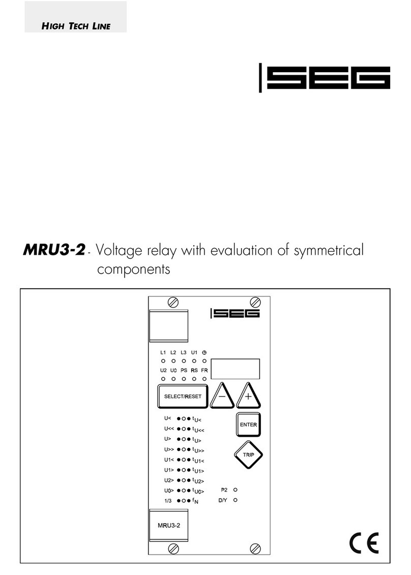
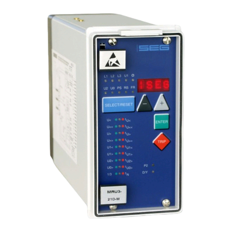
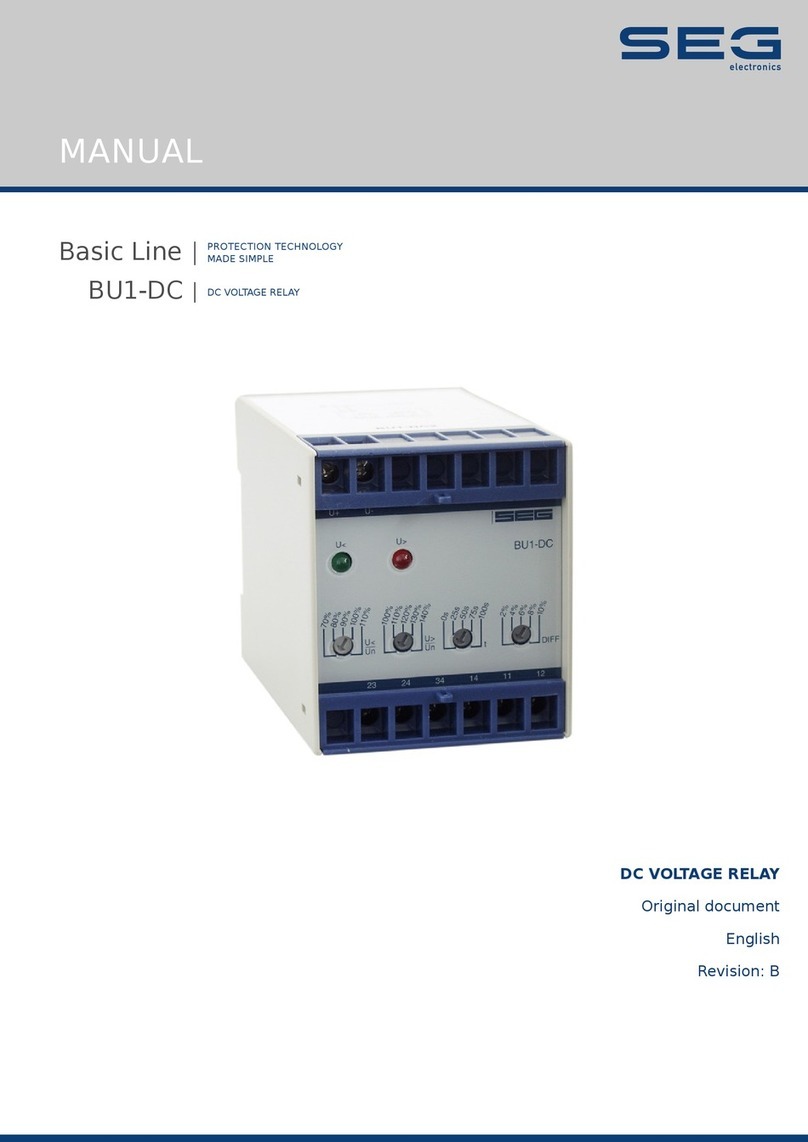
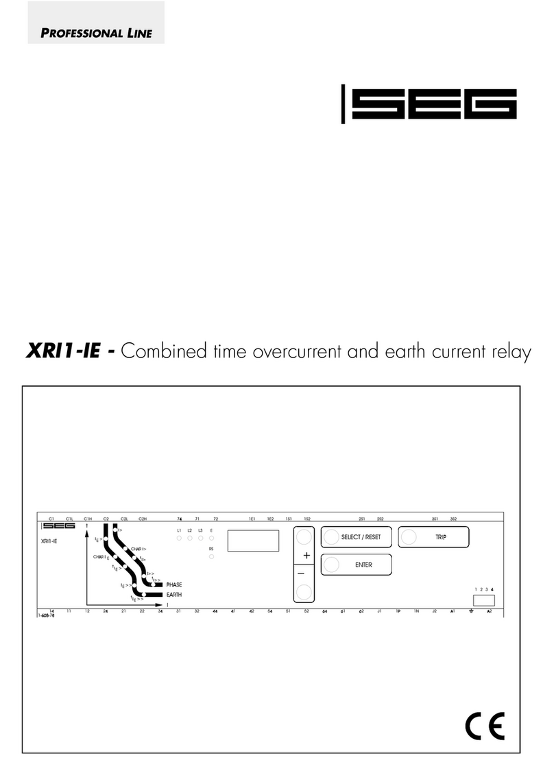
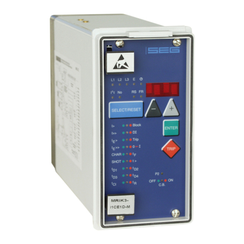
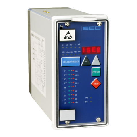
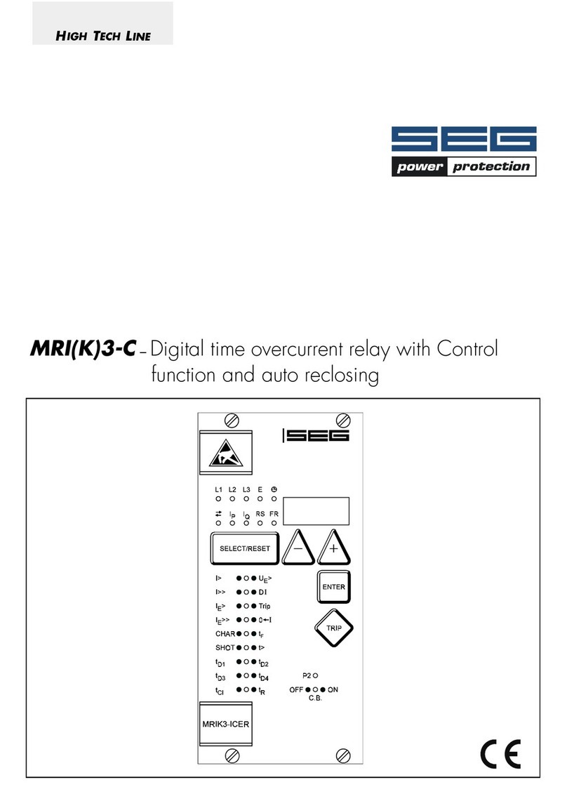
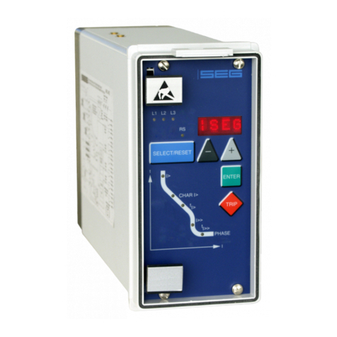
Seg High Tech MRI3-ITE User manual

MRI3-ITE(R) -Time overcurrent relay with thermal replica
and earth current measuring

2TB MRI3-ITE(R) 12.00 E
Contents
1 Introduction and Application
2 Features and characteristics
3Design
3.1 Connections
3.1.1 Analog input circuits
3.1.2 Output relays
3.2 Relay output contacts
3.2.1 Blocking input
3.2.2 External reset input
3.2.3 Fault recorder
3.3 Front plate
4 Working principle
4.1 Analog circuits
4.2 Digital circuits
4.3 Thermal replica
4.3.1 Definitions
4.4 Algorithm
4.5 Earth fault protection
4.5.1 Generator stator earth fault protection
4.5.2 System earth fault protection
4.6 Earth-fault directional feature
(ER-relay type)
4.7 Demand imposed on the main current
transformers
5 Operation and settings
5.1 Display
5.1.1 LEDs
5.2 Setting procedure
5.3 System parameter
5.3.1 Display of measuring values as primary
quantities (Iprim phase)
5.3.2 Display of earth current as primary
quantity (Iprim earth)
5.3.3 Display of residual voltage UE as primary
quantity (Uprim/Usec)
5.3.4 Voltage transformer connection for resi-
dual voltage measuring (3pha/e-n/1:1)
5.3.5 Nominal frequency
5.3.6 Display of the activation storage
(FLSH/NOFL)
5.3.7 Parameter switch/external triggering of
the fault recorder
5.4 Protection parameters
5.4.1 Pickup value of the thermal overload
protection IB,A and IB,T
5.4.2 Constant k
5.4.3 Time constant τ
5.4.4 Pickup current for phase overcurrent
element (I>)
5.4.5 Time current characteristics for phase
overcurrent element (CHAR I>)
5.4.6 Trip delay or time multiplier for phase
overcurrent element (tI>)
5.4.7 Reset setting for inverse time tripping
characteristics in the phase current path
5.4.8 Current setting for high set element (I>>)
5.4.9 Trip delay for high set element (tI>>)
5.4.10 Pickup value for residual voltage UE
(ITER-relay type)
5.4.11 Pickup current for earth fault element (IE>)
5.4.12 WARN/TRIP changeover
5.4.13 Time current characteristics for earth fault
element (CHAR IE) (not ER device type)
5.4.14 Trip delay or time multiplier for earth fault
element (tIE>)
5.4.15 Resetting time for inverse time earth fault
element (not ER-relay type
5.4.16 Current setting for high set element of
earth fault supervision (IE>>)
5.4.17 Trip delay for high set element of earth
fault supervision (tIE>>)
5.4.18 COS/SIN Measurement (ER - relay type)
5.4.19 Block/Trip – time (only ITE-device type)
5.4.20 Circuit breaker failure protection tCBFP
5.4.21 Adjustment of the slave address
5.4.22 Setting of Baud-rate (applies for Modbus
Protocol only)
5.4.23 Setting of parity (applies for Modbus
Protocol only)
5.5 Fault recorder
5.5.1 Adjustment of the fault recorder
5.5.2 Number of the fault recordings
5.5.3 Adjustment of trigger occurences
5.5.4 Pre-trigger time (Tpre)
5.6 Adjustment of the clock
5.7 Additional functions
5.7.1 Blocking of the protective functions
5.8 Indication of measuring and fault values
5.8.1 Indication of measuring values
5.8.2 Unit of the measuring values displayed
5.8.3 Indication of fault data
5.8.4 Fault memory
5.9 Reset
5.9.1 Erasure of fault storage
5.9.2 Reset of the thermal replica register

TB MRI3-ITE(R) 12.00 E 3
6 Relay testing and commissioning
6.1 Power-On
6.2 Testing the output relays and LEDs
6.3 Checking the set values
6.4 Secondary injection test
6.4.1 Test equipment
6.4.2 Example of test circuit for MRI3-ITE
6.4.3 Checking the input circuits and measured
values
6.4.4 Example of a test circuit with earth fault
directional feature
6.4.5 Checking the operating and resetting
values of the relay
6.4.6 Checking the relay operating time
6.4.7 Checking the high set element of the
relay
6.4.8 Checking the external blocking and reset
functions
6.4.9 Testing the external blocking with
Block/Trip function
6.4.10 Test of the CB failure protection
6.5 Primary injection test
6.6 Maintenance
7 Technical data
7.1 Measuring circuits
7.2 Common data
7.3 Setting ranges and steps
7.3.1 Systemparameter
7.3.2 Time overcurrent protection and thermal
replica
7.3.3 Earth fault protection
7.3.4 Earth fault protection (ER-Type)
7.3.5 Determination of earth fault direction
(MRl3-ITER)
7.3.6 BlockTrip – time**
7.3.7 Switch failure protection
7.3.8 Interface parameter
7.3.9 Parameter for the fault recorder
7.4 Tripping characteristics
7.4.1 Thermal characteristic
7.4.2 Preload factor
7.4.3 Inverse time overcurrent protection relay
7.5 Tripping characteristics
7.6 Output relays
8 Order form

4TB MRI3-ITE(R) 12.00 E
1Introduction and Application
The digitial multifunctional relay MRI3-ITE(R) has been
designed as a universal time overcurrent protection re-
lay with thermal replica for generators, transformers
and cables.
The relay gives a complete thermal characteristic of the
electrical equipment to be protected taking into ac-
count its initial load.
The MRI3-ITE(R) furthermore provides a universal time
overcurrent and earth fault protection with the follow-
ing functions:
•Integrated determination of earth fault direction for
application to power system networks with isolated
or arc suppressing coil (Peterson coil) neutral
earthing (ER-relay type),
•independent (Definite) time overcurrent relay.
•inverse time overcurrent relay with selectable charac-
teristics,
•two-element (low and high set) earth fault protection
with definite or inverse time characteristics.
Important:
For additional common data of all MR-relays please
refer to manual „MR-Digital Multifunctional relays“.
2Features and characteristics
•Microprocessor technology with self-supervision,
•measuring of phase current as RMS value,
•digital filtering of the measured values by using dis-
crete Fourier analysis to suppress the high frequence
harmonics and DC components induced by faults or
system operations (earth current only),
•in accordance with the requirements as per
IEC 255-8, VDE 435 part 3011 for overload
relays,
•two parameter sets,
•selectable protective functions between:
definite time overcurrent relay and
inverse time overcurrent relay,
•selectable inverse time characteristics according to
IEC 255-4:
Normal Inverse (Type A)
Very Inverse (Type B)
Extremely Inverse (Type C)
Special characteristics,
•Reset mode for inverse time characteristics selectable,
•high set overcurrent element with instantaneous trip,
•two-element (inverse time and definite time) overcur-
rent relay both for phase and earth faults,
•determination of earth short-circuit fault direction for
systems with isolated or compensated neutral point,
•Display of measuring values as primary quantities,
•measuring of phase current of the short circuit
breaker operation,
•blocking of high set element (e.g. for selective fault
detection through minor overcurrent protection units
after unsuccessful AR),
•the protective functions can be freely assigned to the
output relays (assignment matrix),
•withdrawable modules with automatic short circuiters
of C.T. inputs when modules are withdrawn,
•storage of trip values and switching-off time (tCBFP) of
5 fault occurences (fail-safe of voltage),
•recording of up to eight fault occurences with time
stamp,
•switch failure protection,
•serial data exchange via RS485 interface possible;
alternatively with SEG RS485 Pro-Open Data Proto-
col or Modbus Protocol,
•Display of date and time.

TB MRI3-ITE(R) 12.00 E 5
3Design
3.1 Connections
Figure 3.1: Connection diagram
P1
P2
S1
S2
P1
P2
S1
S2
P1
P2
S1
S2
I1
I2
I3
IE
L1.1
B3
B4 L1.2
L2.1
B5
L2.2
B6
L3.1
B7
L3.2B8
B1
B2
L
1
L2
L3
Figure 3.2: Phase current measuring and earth-current detection
by means of Holmgreen-circuit.
This connection can be used with three existing phase
current transformers when combined phase and earth-
current measuring is required.
Figure 3.3: Earth-fault measuring by means of ring-core C.T. (IE)
When phase-- and earth-fault current measuring are
combined, the connection has to be realized as per
Figure 3.2 and Figure 3.3.

6TB MRI3-ITE(R) 12.00 E
Voltage measuring for the directional detection:
Figure 3.4: Measuring of the phase voltages for the directional
detection at earth-fault protection (IE> and IE>>).
3.1.1 Analog input circuits
The protection unit receives the analog input signals of
the phase currents IL1 (B3-B4), IL2 (B5-B6), IL3 (B7-B8)
and the residual current IE(B1-B2) each via separate
input transformers.
The constantly detected current measuring values are
galvanically decoupled, filtered and finally fed to the
analog/digital converter.
3.1.2 Output relays
Two relays are equipped with two change-over con-
tacts and three relays with each one change-over con-
tact for alarm. Apart from the relay for self-supervision,
all protective functions can be optionally assigned:
•Relay 1: C1, D1, E1 and C2, D2, E2
•Relay 2: C3, D3, E3 and C4, D4, E4
•Relay 3: C5, D5, E5
•Relay 4: C6, D6, E6
•Relay 5: Self-supervision C7, D7, E7
All trip and alarm relays are working current relays, the
relay for self supervision is an idle current relay.
3.2 Relay output contacts
Figure 3.5: Relay outputs
3.2.1 Blocking input
The function for blocking can be parameterized arbi-
trary. When an auxiliary voltage is connected to
D8/E8 those relay functions will be blocked which
were parameterized before (see chapter 5.7.1).
3.2.2 External reset input
See chapter 5.9

TB MRI3-ITE(R) 12.00 E 7
3.2.3 Fault recorder
The MRI3-ITER has a fault value recorder which rec-
ords the measured analog values as instantaneous
values.
The instantaneous values
iL1, iL2, iL3, iE,
are scanned at a raster of 1.25 ms (at 50 Hz) and
1.041 ms (at 60 Hz) and saved in a cyclic buffer. It is
possible to store 1 - 8 fault occurences with a total re-
cording time of 16 s (with 50 Hz) and 13.33 s (with
60 Hz) per channel.
Storage division
Independent of the recording time, the entire storage
capacity can be divided into several cases of distur-
bance with a shorter recording time each. In addition,
the deletion behaviour of the fault recorder can be in-
fluenced.
No writing over
If 2, 4 or 8 recordings are chosen, the complete
memory is divided into the relevant number of partial
segments. If this max. number of fault event has been
exceeded, the fault recorder block any further record-
ings in order to prevent that the stored data are written
over. After the data have been read and deleted, the
recorder to ready again for further action.
Writing over
If 1, 3 or 7 recordings are chosen, the relevant num-
ber of partial segments is reserved in the complete
memory. If the memory is full, a new recording will
always write over the oldest one.
The memory part of the fault recorder is designed as
circulating storage. In this example 7 fault records can
be stored (written over).
Memory space 6 to 4 is occupied.
Memory space 5 is currently being written in
Figure 3.6: Division of the memory into 8 segments, for example
Since memory spaces 6, 7 and 8 are occupied, this
example shows that the memory has been assigned
more than eight recordings. This means that No. 6 is
the oldest fault recording and No. 4 the most recent
one.
trigger occurence
recording duration
Tpre
[s]
Figure 3.7: Basic set-up of the fault recorder
Each memory segment has a specified storage time
which permits setting of a time prior to the trigger
event.
Via the interface RS485 the data can be read and
processed by means of a PC with HTL/PL-Soft4. The
data is graphically edited and displayed. Binary tracks
are recorded as well, e.g. activation and trip.

8TB MRI3-ITE(R) 12.00 E
3.3 Front plate
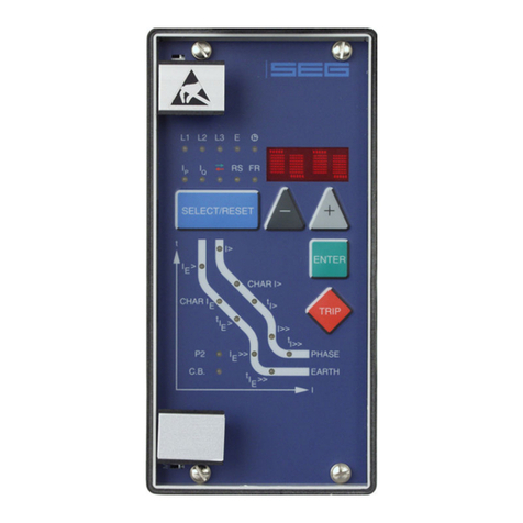
Figure 3.8: Front plate MRI3-ITE
Figure 3.9: Front plate MRI3-ITER
The LED RS, ϑAand ϑTyellow light up yellow (MRI3-ITE)
The LED RS, IPand IQlight up yellow (MRI3-ITER).
All other LEDs are two-coloured. LEDs left to the alpha-
numerical display light-up green during measuring and
red at alarm.
LEDs underneath the pushbutton <SELECT/RESET>
light-up green during setting and inquiry of the setting
values printed left to the LEDs. They light-up red when
the setting values printed at the right to the LEDs are
activated.
The LED labelled with the letters LR is alight while the
fault recorder is being adjusted.

TB MRI3-ITE(R) 12.00 E 9
4Working principle
4.1 Analog circuits
The incoming currents from the main current transform-
ers on the protected object are converted to voltage
signals in proportion to the currents via the input trans-
formers and burden. The noise signals caused by in-
ductive and capacitive coupling are supressed by an
analog RC filter circuit.
The analog voltage signals are fed to the A/D-
converter of the microprocessor and transformed to
digital signals through Sample and Hold circuits. The
analog signals are sampled at 50 Hz (60 Hz) with a
sampling frequency of 800 Hz (960 Hz), namely, a
sampling rate of 1.25 ms (1.04 ms) for every measur-
ing quantity.
4.2 Digital circuits
The essential part of the MRI3-ITE relay is a powerful
microcontroller. All of the operations, from the analog
digital conversion to the relay trip decision, are carried
out by the microcontroller digitally. The relay program
is located in an EPROM (Electrically-Programmable-
Read-Only-Memory). With this program the CPU of the
microcontroller calculates the three phase in order to
detect a possible fault situation in the protected object.
For the calculation of the current value an efficient digi-
tal filter based on the Fourier Transformation (DFFT -
Discrete Fast Fourier Transformation) is applied to sup-
press high frequency harmonics and DC components
caused by fault-induced transients or other system dis-
turbances. The calculated actual current values are
compared with the relay settings.
In case, the time for which a current was above the
preset pickup value, exceeds the trip delay or the
thermal capacity is reached, an alarm signal will be
given. Dependent on their adjustment the output relays
will also be activated.
The relay setting values for all parameters are stored in
a parameter memory (EEPROM - Electrically Erasable
Programmable Read-only Memory), so that the actual
relay settings cannot be lost, even if the power supply
is interrupted. The microprocessor is supervised by a
built-in "watchdog" timer. In case of a failure the
watchdog timer resets the microprocessor and gives
an alarm signal, via the output relay "self supervision".
I
I
=
>
1
I
I
2
%
Alarm
Tripping
Display
tI>
I>
I
tI>>
I>>
I
ϑ
ϑ
ϑ
tIE>
IE>
tIE>>
IE>>
Alarm
Trip
Relay 1
Relay 2
Relay 3
Relay 4
I> Tripping
I> Alarm
I>> Tripping
IE> Alarm
IE> Tripping
IE> Alarm
IE>> Tripping
IE>> Alarm
IL1
IL2
IL3
IE
Assignment
matrix
Blocking
matrix
Figure 4.1: Block diagram

10 TB MRI3-ITE(R) 12.00 E
4.3 Thermal replica
4.3.1 Definitions
Basic current IB:
Set limiting value of the overload current at which the
relay must not trip. This, in general, is the maximally
permissible operating current in consideration of addi-
tional influencing quantities on the heating (e.g. heat
dissipation by transformer oil or air convection).
The settings of the overload characteristics refer to this
basic current.
Time constant k:
Constant to be multiplied by the basic current in order
to determine the current that may be higher than IB.
Instruction for motor protection: k = 1...1.2
MRI3-ITE(R) default value: k = 0.5
Remark:
For the calculation of the temperature equivalent,
only the basic current has to be taken into account:
IB
2~ ϑ.
The constant k is used to determine the pickup value
(IB⋅k) and to calculate the temperature according to
which the object to be protected reaches its tripping
value after expiry of a long time (ϑTrip = k2⋅100%).
•Adjustment of the nominal current with IB(e.g. 1 ⋅IN)
and selection of an overload factor k (e.g. 1.2).
From this, a pickup value of 1.2 ⋅INand a tripping
value of 144% will result.
Thermal time constant τ:
It indicates the time until the temperature of the electri-
cal equipment to be protected reaches 63% of the sta-
tionary operating temperature. (data sheet of the elec-
trical equipment or practical values). Thumb rule: With
the current I being constant, approx. 63% of the
maximal temperature will be reached when t = τ. After
expiry of a time t = 5 ⋅τthe maximal temperature is
almost reached (99%).
The time constant for warming up and that for cooling
down may be different!
Tripping characteristic with preload:
Characteristic with complete memory function, taking
into account the thermal effect of the current before
occurence of the overload in the thermal replica of the
electrical item to be protected.
T(°C)/T
t
(
min
)
tau
100%
max
63%
T (k*I )
B
k^2 *
k^2 *
Figure 4.2: Thermal time constant
τ

TB MRI3-ITE(R) 12.00 E 11
4.4 Algorithm
Based on the defined thermal model, one can deduce
that an energy Q is stored in the electrical equipment.
After expiry of a long time and with a constant current
load, a stationary condition will be achieved in which
the temperature of the electrical equipment does not
increase anymore. The heat supplied for a unit of time
is equal to that released by cooling down (steady en-
ergy balance).
Qreleased = Qsupplied
The supplied thermal energy as well as the tempera-
ture ϑof the electrical equipment in stationary condi-
tion are in proportion to the square of the phase cur-
rent (e.g. ohmic losses and iron losses in the trans-
former).
Q ∼I² or ϑ∼I²
Since the pickup value in the MRI3-ITE is determined
by IB, the following relation is effective:
ϑn ⋅k² ∼(IB⋅k)²
For this purpose, the temperature T that really prevails
in the electrical equipment needs to be known. This
temperature ϑ(in%) is described in the thermal replica
through the temperature equivalent k ⋅IB. When being
loaded with the maximum permissible operating cur-
rent ϑBin stationary condition, the electrical equipment
reaches the maximum allowed operating temperature
ϑB. For this load, the temperature equivalent is defined
as k2⋅100%.
ϑ(%) = (k I
I
B
2
2100%
⋅⋅
)
I.e.: At a load with I = 0.9 x (k ⋅IB) and k ⋅IB = 1.2,
and according to the before indicated definition, the
temperature reaches 81% of the maximum permissible
operating temperature. For an electrical equipment that
- after initial load - will be loaded beyond the admissi-
ble operating current (I > k·IB), the following tempera-
ture curve will result:
T
(%)
t
100%
T
0
T
1
T
2
dt dt
T
max
T(t)
'TRIP'
t0
t'
k ^2 *
Figure 4.3: Warming up of an electrical item
The thermal equivalent ( T = ϑ) is described by an ex-
ponential function.
for (ϑ> ϑ0):
ϑϑϑϑ τ
(') ( ) ( )
max
'
te
t
=+ −⋅−
−
00
1
after transposition:
ϑϑ ϑϑ τ
(') ( )
max max
'
te
t
=+−⋅
−
0
If %100)'t( k2⋅≥ the alarm or trip element is acti-
vated.
The temperature after dt can be calculated as follows:
ϑϑ ϑϑ τ
10
=+−⋅
−
max max
()e
dt
After 2 times dt:
ϑϑ ϑϑ τ
20
2
=+−⋅
−
max max
()e
dt
or
ϑϑ ϑϑ τ
21
=+−⋅
−
max max
()e
dt
general:
ϑϑ ϑ ϑ τ
nn
dt
e
=+−⋅
−
−
max max
()
1
Thus, a recursion formula was established from which
in order to calculate the thermal equivalent ϑn:
•The last value ϑn-1,
•the stationary final value ϑmax for the actual current,
•the adjusted time constant τ,
•and the time since the last calculation dt must be
known.

12 TB MRI3-ITE(R) 12.00 E
Analogous, for the temperature equivalent ϑwith ϑmax
the following formula is applied:
ϑϑτ
(') () ()
'
tI
kI
I
kI e
BB
t
=⋅⋅+−
⋅⋅
⋅−
2
20
2
2
100% 100%
with I = highest measured phase current.
In each new calculation step n, the momentary tem-
perature equivalent is determined as follows:
ϑϑ τ
nn
B
n
n
B
dt
I
kI
I
kI e
=⋅⋅+−
⋅⋅
⋅
−
−
2
21
2
2
100% 100%
() ()
with In: Highest measured phase current in
calculation step n
dt: Time interval between the individual
calculation steps
ϑn-1: Temperature equivalent of the
preceding calculation step
The temperature equivalent ϑn-1 has not been calculated
after start of the protection program (connection of aux-
iliary voltage),
Therefore, the temperature state of the electrical item to
be protected is expected to be cold.
If, however, the electrical equipment has been initially
loaded, it will take approximately 3 x τwarming up, (at con-
stant load) until the thermal equivalent equals the real
state.
Different time constants:
After switching off the electrical equipment (In= 0)
temperature will decrease and tend towards ϑn= 0
(environmental temperature).
e.g.: τcooling down = 2 ⋅τwarming up
Depending on the comparison between the last meas-
ured current and the actual current the cooling down
or warming up constant will be applied for calcula-
tion.
In≥In-1 ⇒warming up
In< In-1 ⇒cooling down
If the relay is supplied by the mains to be protected,
i.e. if the relay is not supplied to auxiliary voltage after
tripping of the mains c.b., the following has to be con-
sidered:
After return of the supply voltage, it is assumed that the
electric item is in cold condition. In this case this as-
sumption does not comply with the reality. Therefore
an external supply voltage should be applied.
The tripping criterion for the alarm or tripping element
of the thermal characteristic is:
ϑTrip > k2⋅100%
The effective values of the measured phase currents
are detected by calculating the root out of the integral
of a period’s momentary current squares. Calculation
of the thermal equivalent is always based on the high-
est of the three phase currents.

TB MRI3-ITE(R) 12.00 E 13
4.5 Earth fault protection
4.5.1 Generator stator earth fault
protection
With the generator neutral point earthed earthed as
shown in Figure 4.4 the MRI3-ITER picks up only to
phase earth faults between the generator and the loca-
tion of the current transformers supplying the relay.
Earth faults beyond the current transformers, i.e. on the
consumer or line side, will not be detected.
Figure 4.4: Generator stator earth fault protetion
4.5.2 System earth fault protection
With the generator neutral point earthed as shown in
Figure 4.5, the MRI3-ITER picks up only to earth faults
in the power system connected to the generator. It
does not pick up to earth faults on the generator termi-
nals or in generator stator.
Figure 4.5: System earth fault protection

14 TB MRI3-ITE(R) 12.00 E
4.6 Earth-fault directional feature
(ER-relay type)
A built-in earth-fault directional element is available for
applications to power networks with isolated or with
arc suppressing coil compensated neutral point.
For earth-fault direction detection it is mainly the ques-
tion to evaluate the power flow direction in zero se-
quence system. Both the residual voltage and neutral
(residual) current on the protected line are evaluated to
ensure a correct direction decision.
In isolated or compensated systems, measurement of
reactive or active power is decisive for earth-fault de-
tection. It is therefore necessary to set the relay to
measure according to sin ϕor cos ϕmethods, de-
pending on the neutral-point connection method.
The residual voltage UErequired for determining earth
fault direction can be measured in three different
ways, depending on the voltage transformer connec-
tions.
(refer to Table 4.1)
Total current can be measured by connecting the unit
either to a ring core C.T. or to current transformers in a
Holmgreen circuit. However, maximum sensitivity is
achieved if the MRI3-ITER protective device is con-
nected to a ring core C. T. (see Figure 3.3).
The pick-up values IE> and IE>> (active or reactive cur-
rent component for cos ϕor sin ϕmethod) for ER-relay
types can be adjusted from 0.01 to 0.45 x IN.
Adjustment
possibility
Application Voltage transformer
connections
Measured
voltage at
earth fault
Correction fac-
tor for residual
voltage
„3pha“
3-phase voltage
transformer connected
to terminals A3, A5,
A7, A2 √3 x UN= 3 x U1N K = 1 / 3
„e-n“
e-n winding
connected to
terminals A3, A2
UN= √3 x U1N K = 1 / √3
„1:1“
Neutral-point voltage
(= residual voltage)
terminals A3, A2
U1N = UNE K = 1
Table 4.1: Connection of voltage transformers

TB MRI3-ITE(R) 12.00 E 15
Figure 4.6: Phase position between the residual voltage and zero sequence current for faulted and non-faulted lines in case of isolated
systems (sin
ϕ
)
UE- residual voltage
IE- zero sequence current
IC- capacitive component of zero sequence cur-
rent
IW- resistive component of zero sequence current
By calculating the reactive current component (sin ϕ
adjustment) and then comparing the phase angle in
relation to the residual voltage UE, the ER/XR-relay
type determines whether the line to be protected is
earth-faulted.
On non-earth-faulted lines, the capacitive compo-
nent Ic(a) of the total current precedes the residual
voltage by an angle of 90°. In case of a faulty line
the capacity current IC(b) lags behind the residual
voltage at 90°.
Figure 4.7: Phase position between the residual voltage and zero sequence current for faulted and non-faulted lines in case of
compensated systems (cos
ϕ
)
UE- residual voltage
IE- zero sequence current
IL- inductive component of zero sequence current
(caused by Petersen coil)
IC- capacitive component of zero sequencel cur-
rent
IW- resistive component of zero sequence current
In compensated mains the earthfault direction cannot
be determined from the reactive current components
because the reactive part of the earth current depends
upon the compensation level of the mains. The ohmic
component of the total current (calculated by cos ϕad-
justment) is used in order to determine the direction.
The resistive component in the non-faulted line is in
phase with the residual voltage, while the resistive
component in the faulted line is opposite in phase with
the residual voltage.
By means of an efficient digital filter harmonics and
fault transients in the fault current are suppressed. Thus,
the uneven harmonics which, for instance, are caused
an electric arc fault, do not impair the protective func-
tion.

16 TB MRI3-ITE(R) 12.00 E
4.7 Demand imposed on the main
current transformers
The current transformers have to be rated in such a
way, that a saturation should not occur within the fol-
lowing operating current ranges:
Independent time overcurrent
function: K1 = 2
Inverse time overcurrent function: K1 = 20
High-set function: K1 = 1.2 - 1.5
K1 = Current factor related to set value
Moreover, the current transformers have to be rated
according to the maximum expected short circuit cur-
rent in the network or in the protected objects.
The low power consumption in the current circuit of
MRI3-ITER, namely <0,2 VA, has a positive effect on
the selection of current transformers. It implies that, if
an electromechanical relay is replaced by MRI3-ITER,
a high accuracy limit factor is automatically obtained
by using the same current transformer.

TB MRI3-ITE(R) 12.00 E 17
5Operation and settings
5.1 Display
Function Display shows Pressed pushbutton Corresponding LED
Normal operation SEG
Measured operating values actual measured values,
related to IN,
Temperature equivalent in %
<SELECT/RESET>
one time for each value
L1, L2, L3, E
ϑA, ϑT, IP, IQ
Measuring range overflow max. <SELECT/RESET> ϑAund ϑT
Display of the second rated repetition current SEC 0.002-50.0 kA=prim <+> <-><SELECT/RESET> L1, L2, L3, E
Rated frequency f = 50 / f = 60 <+> <-><SELECT/RESET>
LED-blinking after activation FLSH/NOFL <+> <-><SELECT/RESET>
Parameter switch/external triggering of the
fault recorder
SET1, SET2, B_S2, R_S2,
B_FR, R_FR, S2_FR
<+> <-><SELECT/RESET> P2
Constant k Factor for pickup current <+> <-><SELECT/RESET> kAand kT
Time constant τCooling time/warming up
time constant
<+> <-><SELECT/RESET> τCand τW
Blocking of function EXIT <+> until max. setting
value
LED of blocked
parameter
Characteristics DEFT,NINV, VINV, EINV,
LINV, RINV,
<+> <-><SELECT/RESET> CHAR I>
Characteristics DEFT, NINV, VINV, EINV,
LINV, RINV
<+> <-><SELECT/RESET> CHAR IE>
Switch failure protection CBFP after tripping C. B.
Recorded fault data Phase currents, earth currents
and temperature equivalent
<SELECT/RESET>
one time for each phase
L1, L2, L3, E
ϑAand ϑT
Enquiry failure memory FLT1, FLT2..... <+> <-><SELECT/RESET> L1, L2, L3, E
I>, I>>, IE>, IE>>,
Delete failure memory wait <+> <-><SELECT/RESET>
Relay trip TRIP <TRIP> or after fault tripping
Secret password input „XXXX“ <+><-> <ENTER>
<SELECT/RESET>
System reset SEG <SELECT/RESET>
for about 3 s
Manual trip TRI? <TRIP> three times
Inquire password PSW? <TRIP><ENTER>
Blocking of protection function BLOC, NO_B <ENTER> und <TRIP>
Change over the blockage function ²)PR_B, TR_B <ENTER> und <TRIP>; <+><-
>
I>, I>>, IE>, IE>>, oder tI>,
tI>>, tIE>, tIE>>
Relay assignment e. g. _ 2 _ _ <ENTER> and <TRIP>
Trigger signal for the fault recorder P_UP; A_PI; TRIP; TEST <+> <-><SELECT/RESET> FR
Number of fault occurences S = 2, S = 4, S = 8 <+> <-><SELECT/RESET> FR
Display of date and time Y = 99, M = 10, D = 1,
h = 12, m = 2, s = 12
<+> <-><SELECT/RESET> !
Slave address of serial interface 1-32 <+> <-><SELECT/RESET> RS
Baud-Rate 1) 1200-9600 <SELECT/RESET> <+><-> RS
Parity-Check 1) even odd no <SELECT/RESET> <+><-> RS
Parameter switch SET1; SET2 <+> <-><SELECT/RESET> P2
Setting values:
Currents and time delays Current and time
settings
<SELECT/RESET>
one time for each
parameter
IB,A; IB,T; kA; kT;
I>; CHAR I>; tI>; I>>;
tI>>;
IE>; CHAR IE>; tIE>; IE>>;
tIE>>
Save parameter? SAV? <ENTER>
Save parameter! SAV! <ENTER> for about 3 s
Display of software-version First part (e.g. D21-)
Second part (e.g. 1.00)
<TRIP>
one time for each part
Setting of the transformer connections of
UE>
1:1; e-n; 3pha <+> <-><SELECT/RESET> UE>
Table 5.1: possible indication messages on the display
1) only Modbus 2) only ITE

18 TB MRI3-ITE(R) 12.00 E
5.1.1 LEDs
LED-Name Mode Colour LED-Display Meaning
L1, L2, L3, E Display of measuring
values
green continuously Current measuring
(phase or earth current)
ϑAand ϑTDisplay of measuring
values
yellow continuously Measuring of the temperature
equivalent (%)
L1, L2, L3, E Pickup red flashing Overcurrent pickup
(phase or earth current)
IP, IQ* Display of measuring
values
yellow continuously Wirk- und Blindstromanteil f. Erd-
strom
ϑAand ϑTPickup yellow flashing Base current exceeded (IB*k)
ϑAand ϑT*Pickup green flashing Base current exceeded (IB*k)
ϑAand ϑT*Pickup red flashing Base current exceeded (IB*k)
L1, L2, L3, E,
(I>, I>>, IE>, IE>>)
After pickup green flashing (short) Pickup signalized (In combination
with trip element only)
L1, L2, L3, E Tripping red continuously Overcurrent tripping
(phase or earth current)
L1, L2, L3, E,
ϑAand ϑT
(IB,A, IB,T)
After pickup yellow flashing (short) Pickup signalized (In combination
with trip element only)
ϑAWarning at k2⋅100% yellow continuously Temperature limit of overload low set
element reached
ϑTTripping at k2⋅100% yellow continuously Temperature limit of trip element
reached
ϑA* Warning at k2⋅100% yellow continuously Temperature limit of overload low set
element reached
ϑT* Tripping at k2⋅100% yellow continuously Temperature limit of trip element
reached
IB,A Setting green continuously Setting switch point
kASetting red continuously Define constant
IB,A (ϑA)Pickup green flashing Base current exceeded (IB,A*k)
IB,A (ϑA)Tripping red flashing Temperature limit of overload low set
element reached
IB,T Setting green continuously Setting switching point
kTSetting red continuously Define constant
IB,A (ϑT)Pickup red flashing Base current exceeded (IB,T*k)
IB,T (ϑT)Tripping red continuously Temperature limit of trip element
reached
τCSetting green continuously Cooling time constant
τWSetting red continuously Warming up constant
I> Setting green continuously Setting switching point I>
CHAR I> Setting green continuously Select characteristic
tI> Setting red continuously Setting time delay tI>
tI>, CHAR I> Setting red/green continuously Reset mode activating
I>, tI> Pickup red flashing Pickup of I>
I>, tI> Tripping red continuously I> tripped
I>> Setting green continuously Setting switching point I>>
tI>> Setting red continuously Setting time delay tI>>
I>>, tI>> Pickup red flashing Pickup of I>>
I>>, tI>> Tripping red continuously I>> tripped
IE> Setting green continuously Setting switching point I>
CHAR IE>** Setting green continuously Select characteristic
tIE> Setting red continuously Setting time delay tIE>
tIE>, CHAR IE** Setting red/green continuously Reset mode activating
→←*Setting/tripping red continuously Directional feature for earth current
IE>, tIE> Pickup red flashing Pickup of IE>
IE>, tIE> Tripping red continuously IE> tripped
IE>> Setting green continuously Setting switching point IE>>
tIE>> Setting red continuously Setting time delay tIE>>
IE>>, tIE>> Pickup red flashing Pickup of IE>>
IE>>, tIE>> Tripping red continuously IE>>, tripped
RS Setting yellow continuously Setting slave address
Table 5.2: LED-indication
* MRI3-ITER type only **only MRI3-ITE type

TB MRI3-ITE(R) 12.00 E 19
5.2 Setting procedure
After push button <SELECT/RESET> has been pressed,
always the next measuring value is indicated. Firstly
the operating measuring values are indicated and then
the setting parameters. By pressing the <ENTER> push
button the setting values can directly be called up and
changed. Before parameter setting can be started the
relevant password must be entered (refer to Chapter
4.4 of the "MR Digital Multifunctional Relay" Descrip-
tion).
5.3 System parameter
5.3.1 Display of measuring values as
primary quantities (Iprim phase)
With this parameter it is possible to show the indica-
tion as primary measuring value. For this purpose the
parameter must be set to be equal with the rated pri-
mary CT current. If the parameter is set to "sec", the
measuring value is shown as a multiple of the rated
secondary CT current.
Example:
The current transformer used is of 1500/5 A. The
flowing current is 1380 A. The parameter is set to
1500 A and on the display "1380 A" are shown. If
the parameter is set to "sec", the value shown on the
display is "0.92" x In.
Note:
The pick-up value is set to a multiple of the rated sec-
ondary CT current.
5.3.2 Display of earth current as primary
quantity (Iprim earth)
The parameter of this function is to be set in the same
way as that described under 5.3.1.
5.3.3 Display of residual voltage UE
as primary quantity (Uprim/Usec)
The residual voltage can be shown as primary measur-
ing value. For this parameter the transformation ratio of
the VT has to be set accordingly. If the parameter is set
to "sec", the measuring value is shown as rated secon-
dary voltage.
Example:
The voltage transformer used is of 10 kV/100 V. The
transformation ratio is 100 and this value has to be set
accordingly. If still the rated secondary voltage should
be shown, the parameter is to be set to 1.
5.3.4 Voltage transformer connection for
residual voltage measuring
(3pha/e-n/1:1)
Depending on the connection of the voltage trans-
former of ER/XR-relay types three possibilities of the
residual voltage measurement can be chosen
(see chaper 4.6).
5.3.5 Nominal frequency
The adapted FFT-algorithm requires the nominal fre-
quency as a parameter for correct digital sampling
and filtering of the input currents.
By pressing <SELECT> the display shows "f=50" or
"f=60". The desired nominal frequency can be ad-
justed by <+> or <-> and then stored with <ENTER>.
5.3.6 Display of the activation storage
(FLSH/NOFL)
If after an activation the existing current drops again
below the pickup value, e.g. I>, without a trip has
been initiated, LED I> signals that an activation has
occured by flashing fast. The LED keeps flashing until it
is reset again (push button <RESET>). Flashing can be
suppressed when the parameter is set to NOFL.

20 TB MRI3-ITE(R) 12.00 E
5.3.7 Parameter switch/external
triggering of the fault recorder
By means of the parameter-change-over switches it is
possible to activate two different parameter sets.
Switching over of the parameter sets can either be
done by means of software or via the external inputs
RESET or blocking input. Alternatively, the external in-
puts can be used for Reset or blocking of the triggering
of the fault recorder.
Software-
parameter
Blocking input
used as
RESET input
used as
SET1 Blocking input RESET input
SET2 Blocking input RESET input
B_S2 Parameter switch RESET input
R_S2 Blocking input Parameter
switch
B_FR External trigger-
ing of the fault
recorder
RESET input
R_FR Blocking input External trigger-
ing of the fault
recorder
S2_FR Parameter switch External trigger-
ing of the fault
recorder
With the settings SET1 or SET2 the parameter set is
activated by software. Terminals C8/D8 and D8/E8
are then available as external reset input or blocking
input.
With the setting B_S2 the blocking input (D8, E8) is
used as parameter-set change-over switch. With the
setting R_S2 the reset input (D8, E8) is used as pa-
rameter-set change-over switch. With the setting B_FR
the fault recorder is activated immediately by using the
blocking input. On the front plate the LED FR will then
light up for the duration of the recording. With the set-
ting R_FR the fault recorder is activated via the reset
input. With the setting S2_FR parameter set 2 can be
activated via the blocking input and/or the fault re-
corder via the reset input.
The relevant function is then activated by applying the
auxiliary voltage to one of the external inputs.
Important note:
When functioning as parameter change over facility,
the external input RESET is not available for resetting.
When using the external input BLOCKING the protec-
tion functions must be deactivated by software block-
ing separately (refer to chapter 5.7.1).
5.4 Protection parameters
5.4.1 Pickup value of the thermal
overload protection IB,A and IB,T
For basic current IB, the max. permissible operating
current or optionally the rated current of the object to
be protected has to be used in either case based on
rated secondary quantities. 100% of the thermal
equivalent ϑthen corresponds to the max. permissible
operating temperature or optionally to the rated oper-
ating temperature.
Conversion to secondary values are to be done as per
the following formula:
II
nI
B
Bprim
INMRI
=⋅
,
,
1
with IB,prim: max. base current in A
nI: c.t. ratio
IN.MRI: rated current
Example:
9,0
A1
1
500
A450
I
A1I;
A1
A500
n;A450I
B
MRIN,
Iprim,B
=⋅=
===
5.4.2 Constant k
Constant k describes the admissible overload factor.
This factor changes the pickup value and the tripping
value of the relay.
5.4.3 Time constant τ
ττ
τ
Details on the time constants τCand τWcan either be
taken from the electrical equipment’s data sheets or es-
timated on the base of practical values.
Additional influencing factors are a.o. the environ-
mental heat storing and heat conducting capacity (e.g.
mode of cable laying on the ground, in tubes or
shafts, or the additional cooling by forced convection
of transformers through fans).
5.4.4 Pickup current for phase
overcurrent element (I>)
The setting value for this parameter that appears on the
display is related to the nominal current (IN) of the re-
lay. This means: pickup current (Is) = displayed value x
nominal current (IN) e.g. displayed value = 1.25 then,
Is = 1.25 x IN.
This manual suits for next models
1
Table of contents
Other Seg Relay manuals
Popular Relay manuals by other brands

Siemens
Siemens 3SK1120 Series Original operating instructions

Maevi
Maevi Power Relay quick start guide

Pilz
Pilz PNOZ X6 operating instructions

MRS
MRS Toggle Relay M3 12 V operating instructions

Pilz
Pilz P2HZ X4P operating instructions

Sterling Power Products
Sterling Power Products Pro Latch R 80 instructions