Seiko 4T57A Installer manual

[SPECIFICATIONS]
1/11
PARTS LIST/TECHNICALGUIDE
ANALOGUE QUARTZ Cal. 4T57A
Cal. No.
Item
Interval of hands movement
Driving system
Additional function
Loss/gain
Regulation system
Gate time for rate measurement
Power
supply
Battery No.
Battery voltage
Battery life
Number of jewels
C r o w n
operation
Normal position
1st click position
2nd click position
Current consumption
Coil resistance
4T57A
Indicated by the Hour, Minute, Second and Calendar
Up to 1 minutes in 1/10 second (2 seconds per round)
Up to 60 minutes in 1 second split time
Two pole stepping motor, Step motor 3 pieces
3 Hands (Hour, Minute, Second)
Chronograph (Minute, Second, 1/10 second)
Calendar
Use 10-second gate
0 jewels
Diameter
Outside : Ø29.50 mm (12H - 6H) × 26.00 mm
Casing: Ø28.80 mm (12H - 6H)
4.57 mm
1 second
Free
Date setting(clockwise)
Time setting, hand position adjustment / resetting the circuit
Nil
Movement: Less than 2.20 µA
Circuit block: Less than 1.04 µA
Monthly rate: Less than 20 seconds (at normal temperature range)
4002004 (COIL BLOCK A)
1.0 - 1.2 KΩ
4002923 (COIL BLOCK B)
1.28 - 1.48 KΩ
1.55 V

Cal. 4T57A
2/11
PARTS LIST
AND
10 Date driving wheel
0802 368
3 DIAL
0817 368
0836 369
15 CHRONOGRAPH
0888 009
0962 891
CHRONOGRAPH
0885 002
0737 891
CHRONOGRAPH
0886 003
21 CHRONOGRAPH
0888 009
0271 407
AND
0806 368
18 CHRONOGRAPH
0902 008
0886 001
0885 002
0126 368
4 AUXILIARY TRAIN
0012 079
0808 368
Order of disassembly: 1 55
Order of assembly: 55 1
Types of oil
AO-3
AO-2
Oil quantity
Normal quantity
0810 368
*All parts code are subject to change without notice.

Cal. 4T57A
3/11
PARTS LIST
0351 892
0012 079
4250 064
27 CIRCUIT BLOCK
4004 259
0012 079
0125 331
4270 358
PINION (B)
0701 014
4146 177
33 COIL BLOCK (B)
4002 923
34 ROTOR STATOR (B)
4239 357
0012 079
0125 331
4146 177
38 COIL BLOCK (B)
4002 923
39 ROTOR STATOR (B)
4239 357
0701 014
0012 079
*All parts code are subject to change without notice.

Cal. 4T57A
4/11
PARTS LIST
0241 178
0231 904
0701 904
4146 890
0281 904
49 COIL BLOCK (A)
4002 904
50 ROTOR STATOR (A)
4239 357
0391 368
0383 368
0384 470
0282 890
0962 890
0261 150
0125 248
*All parts code are subject to change without notice.
0221 157
*1
*1

Cal. 4T57A
5/11
PARTS LIST
lTools and consumables required for disassembling/reassembling
•Movement holder
• Watch oils
AO-3 AO-2
Remarks
Color of
background
Black
3 o’clock
3 o’clock
Position of
crown
3 o’clock
3 o’clock
Position of
calendar frame Color of figure
Black
Part code
0878 220
0878 221

Cal. 4T57A
6/11
TECHNICAL GUIDE
-
spond with the time actually displayed. Before using the watch, therefore, be sure to reset the IC follow-
ing the procedure below.
If any of the stopwatch hands should move improperly, also follow the same procedure.
1. Pull out the crown to the second click position.
2. Press the buttons “A” and “B” simultaneously for 2 seconds,
and then, release the buttons. The stopwatch second hand
turns counterclockwise and stopwatch 1/10 second hand turns
clockwise, and then return to where they were.
3. Press button “A” or “B” to reset the stopwatch hands to ”0”
position.
* By pressing button “A” , set the stopwatch 1/10 second hand.
* By pressing button “B”, set the stopwatch second and minute
hands.
4. Turn the crown to set the hour, and minute and 24-hour hands
to the desired time, and push the crown back to the normal po-
sition.
●Remarks on installing the battery
1) After the battery is replaced with a new one, or after the bat-
tery is reinstalled following the repairing procedures, be sure
to touch the AC terminal of circuit block and the switch spring
with conductive tweezers to reset the circuit as illustrated at
right.

Cal. 4T57A
7/11
TECHNICAL GUIDE
1. Place the movement directly on a movement holder or
the like and press in the hands.
2. Install the hour, minute and second hands at the
“12”o’clock position.
3. Install the chrono minute and second hands at the
“0”o’clock position.
●How to install
[ Reference ] The power of press hands
Minute & Hour Hands < 5kg
Second Hand < 5kg
Chrono Minute & Second Hands < 3kg
arrow, pull out the setting stem.
●How to remove
Push
●How to remove or install the battery
1) Remove the hook of the switch spring's battery clamp.
2) Insert the battery sideways, and have the hook of the switch spring's battery clamp catch the
main plate.
Battery clamp
Main plate
1) When Removing 2) When Installing
16 Switch spring

Cal. 4T57A
8/11
TECHNICAL GUIDE
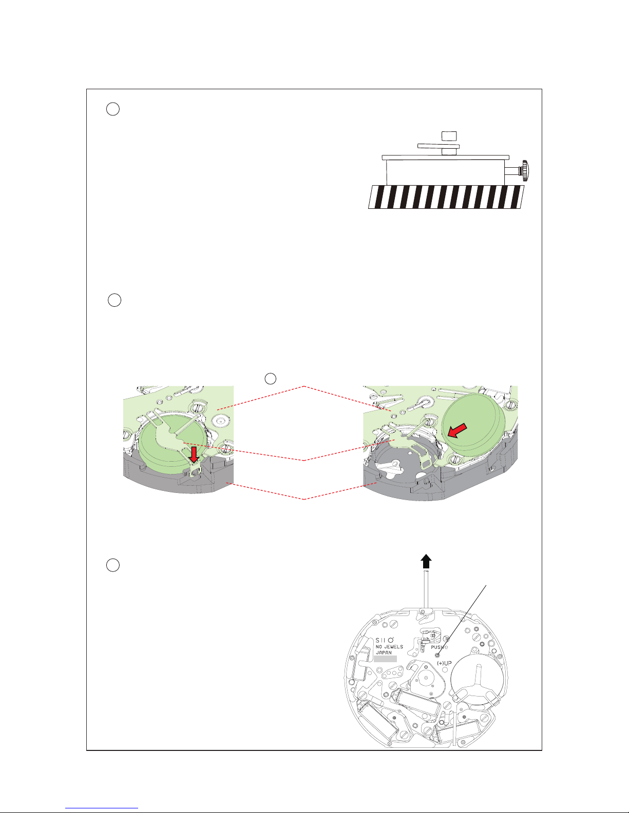
REMARKSONINSPECTIONANDMEASUREMENT
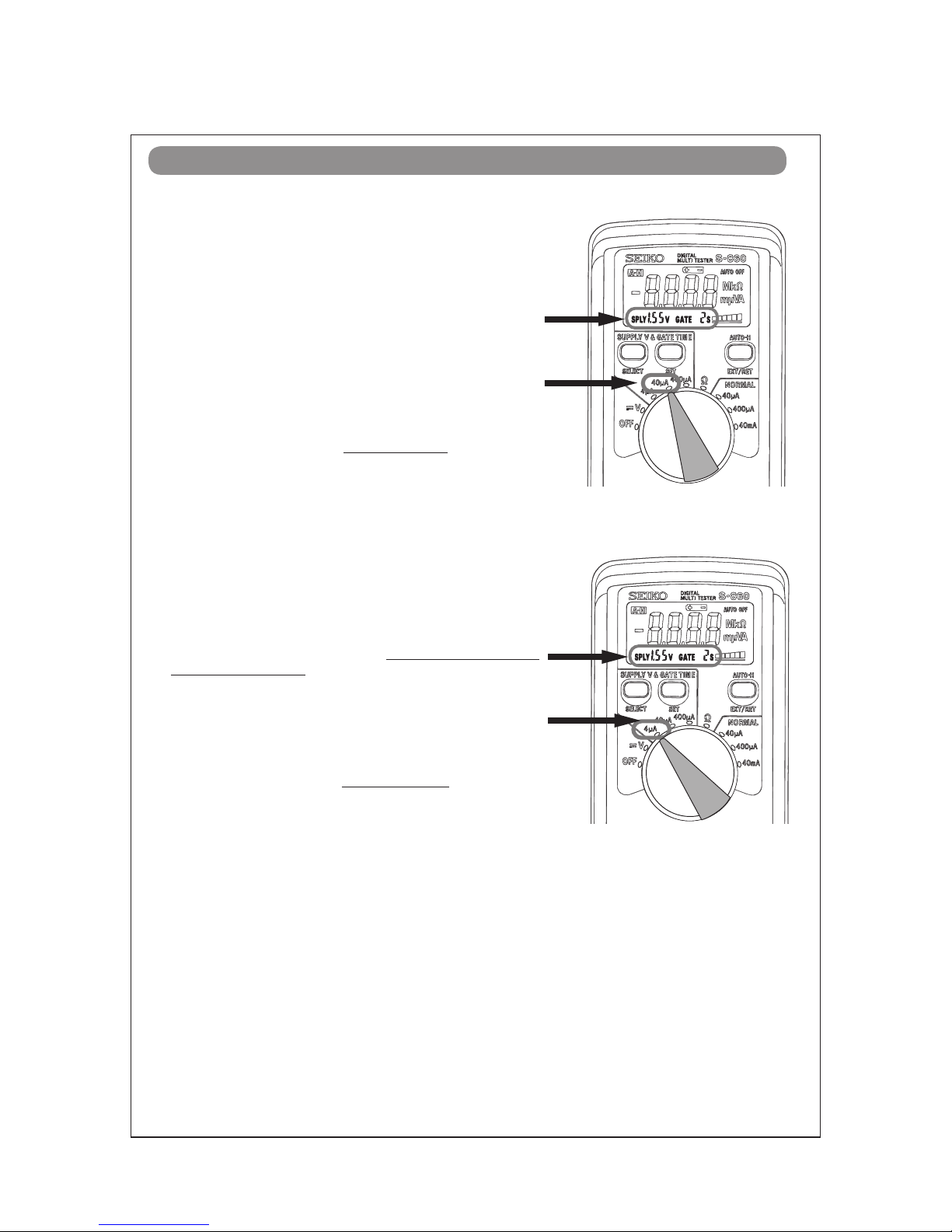
1. To measure the current consumption for the whole move-
ment, connect the (-) probe to the battery connection (-)
and (+) probe to the other metal part of the movement,
such as battery clamp or circuit block cover.
digital multi-tester (S-860), use the range of 40 µ A of SUP-
2. Connect the AC component to the positive terminal for 2
seconds until a short circuit occurs to reset the integrated
circuit.
10 seconds until a stable measurement is obtained, and
then read the measurement.
4. Make sure the read value is less than 2.2 µ A.
●How to measure the current consumption for the whole movement
●How to measure the current consumption for the CIRCUIT BLOCK alone
1. To measure the current consumption for the CIRCUIT BLOCK
alone, connect each probe to the appropriate positive (+) or
negative (-) input terminal of the CIRCUIT BLOCK (please re-
fer to “Structure of the CIRCUIT BLOCK” below).
Multi-Tester S-860, use the range of 4 µ A of SUPPLY V (= 1.55
2. Repeat the same procedures as 2. and 3. of measuring cur-
rent consumption for the whole movement above.
block alone, be careful not to damage or deform the pattern
of the circuit block.
3. Make sure the read value is less than 1.04 µ A.

Cal. 4T57A
9/11
TECHNICAL GUIDE
●Value checking – coil resistance (coil blocks)
Check the resistance of each coil block if they are within the range in the following table.
1.0 KΩ– 1.2 KΩ
1.28 KΩ– 1.48 KΩ
COIL BLOCK (A)
COIL BLOCK (B)
4002904
4002923
[Structure of the CIRCUIT BLOCK]
Input terminal (+)
Input terminal (-)
Output terminal(hand moving)
Crystal unit
Output terminal(CG)
C=MOS=IC

Cal. 4T57A
10/11
TECHNICAL GUIDE
Minute hand
Hour hand
Stopwatch minute hand (moves
in minute increments)
Second hand
Stopwatch second hand (moves
in second increments)
Stopwatch 1/10 second hand (moves
in 1/10 second increments)
But ton "A" in stopwatch
function: Start/Stop
First click: Date setting
Second click: Time setting
Crown at normal position
Button "B" in stopwatch function:
Split/Slit release/Reset
* The measurement time indicated by the stopwatch hands that move independently of center hands.
* Stopwatch 1/10 second hand moves for a first minute. After one minute, it indicates the measurement
time when it is stopped.
DISPLAYANDCROWN/BUTTONOPERATION
2. Turn the crown clock-
wise until the previous
day’s date appears.
3. Pull out the crown to
the second click when
the second hand is at
the 12 o’clock position.
It will stop on the spot
and advance the hour
and minute hands by
turning the crown.
(Check that AM/PM is
set correctly.)
the second click posi-
tion, do not press any
button. Otherwise, the
chronograph hands
will move.
1. Pull out the crown to
the first click.
4. Push the crown back in
to the normal position in
accordance with a time
signal.
* Do not set the date between 9:00 P.M. and 1:00 A.M.
Otherwise, the day may not change properly. If it is necessary to set the date during that time period,
First change the time to any time outside it, set the date and then reset to the correct time.
TIMESETTING

Cal. 4T57A
11/11
TECHNICAL GUIDE
The measurement time is indicated by the stopwatch hands that move independently of the center
hands.
The stopwatch can measure up to 60 minutes in second. (The watch indicates the measurement time in
second increments by ignoring off the 1/10 seconds obtained.)
Standard measurement
Stopwatch minute hand
Stopwatch second hand
9.8/10 seconds
HOWTOUSETHESTOPWATCH
A
B
A
Stopwatch 1/10 second hand
(Game over)
Accumulated elapsed time measurement
A A/A A B
START STOP
(Start of game) (Time out)
(Restart of game)
5 minutes 10, 8/10 seconds 20 minutes 00 seconds
*Restart and stop of the stopwatch can be repeated as many times as necessary by pressing button A
Split time measurement
START SPLIT/
2 minutes 50 seconds 15 minutes 10 seconds
*Measurement and release of the split time can be repeated as many times as necessary by pressing button B.
AA A
B
A
B
A
B
Copyright©2014 by
Table of contents
Other Seiko Watch manuals

Seiko
Seiko 2A27 User manual

Seiko
Seiko V157 User manual

Seiko
Seiko S822 User manual

Seiko
Seiko C-22 User manual

Seiko
Seiko 1B25 User manual

Seiko
Seiko H558-5009 Operating manual

Seiko
Seiko SSC141P1 User manual

Seiko
Seiko SKA896P1 User manual

Seiko
Seiko 5M42A Quick start guide

Seiko
Seiko 5M54A Quick start guide

Seiko
Seiko S810 User manual

Seiko
Seiko Pulsar Y182 User manual

Seiko
Seiko A257A Quick start guide

Seiko
Seiko Presage SRQ033J User manual

Seiko
Seiko ANALOGUE QUARTZ SOLAR V145 User manual

Seiko
Seiko ALBA W074 User manual

Seiko
Seiko Data-2000 User manual

Seiko
Seiko SSA392J1 User manual

Seiko
Seiko 5M63 User manual

Seiko
Seiko 6A32 User manual