Seiwa LCIP79 User manual

Thank you very much for purchasing our LED lighting fittings.
Please read this instruction manual to use the product properly.
1) Prior to installing the fitting, check if the product is as per your order.
2) Check for a loose or damaged part due to an accident in transit, etc.
1)
- Installation work should be done properly by a ualified electrician in accordance with the related laws and the instruction manual.
- For safety, Installation work should be done by at least two workers.
- Related laws and regulations refer to the Industrial Safety and Health Act and the Electrical E uipment Technical Standards.
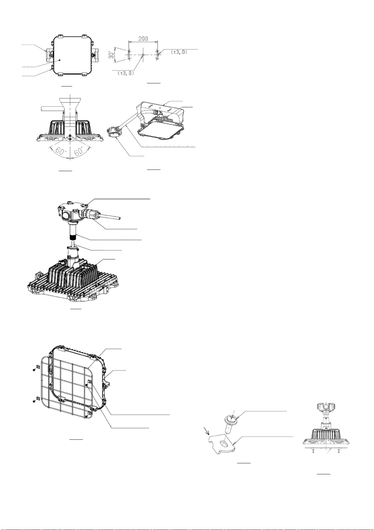
■Direct Mount Type, Pipe Pendant Type, Bracket Type
①
NB:
②
③
④
⑤
⑥
⑦
NB1:
NB2: Caulk the threaded connections.
NB3:
0.61-0.265A
After connecting the lamp power cable (black/white: power line,
green: ground line), remove the suspension hook from the hook
hole and store it in the junction box lid.
Attach the junction box cover to the junction box using the four
cross-recessed hex bolts.
For the bracket type, the lamp house may be installed within an
angle range of 0° (down) to 45° (obli ue).
For the direct mount and Pipe pendant type, The lamp house
may be installed within an angle range of 0° (down).
The electrical characteristic data is given below.
Ra73
-Guard
-Glare cut panel
-Fall prevention
wire
Option
Bracket
0.81-0.34A
Pole B type, C type
LCIP79 79.5-77.5W
Average Color
rendering index Installation Type
Direct mount
Pipe pendant
Floodlight
Model
11E0200776A11
To be conserved
Instruction Manual
Vapor Tight type LED Lighting Fittings LCIP
Performance
After installing the product, be sure to hand this manual over to the user of the product.
Prior to use
IP
rating
100-242V AC
(50/60Hz)
Replacement demand
Input
Current
Power
Consumption
Input Voltage
(Fre uency)
0.375-0.18A
59.5-59.0W
Highway type
IP65
After adjusting the rotational position of the fitting and junction box,
tighten the set screws (3 locations) to secure them.
Use tools to securely tighten the hanging pipe, locking screw, and
cross-recessed hex bolt. Insufficient tightening may cause the
device to fall.
Securely attach the junction box to a horizontal mounting surface
using M6 bolts or bolts of e uivalent strength.
For the bracket type, fix it on a vertical mounting surface
securely.
Screw the pipe into the retainer.
Screw the junction box lid onto the suspension pipe.
Lift the fitting and hook the hanging hook into the hanging hook
hook hole of the junction box.
Stanchion type
Names of the Components and Installation Method
Special Direct Mount type 36.5-37.5W
LCIP60
LCIP37
4-φ8 Mounting Holes
Fitting ④⑦
②③
③⑤⑥
Fig. 1
Junction
Box
①④⑥⑦
Suspension Hook ④⑤
Suspension
Pipe
Junction
Box
Lid
4-Locking Screws
Lid Packing
Retainer ②
Hanging Hook Hole
④
4
-
Cross Recessed Hex Bolt
⑥
⑦
- 1 -

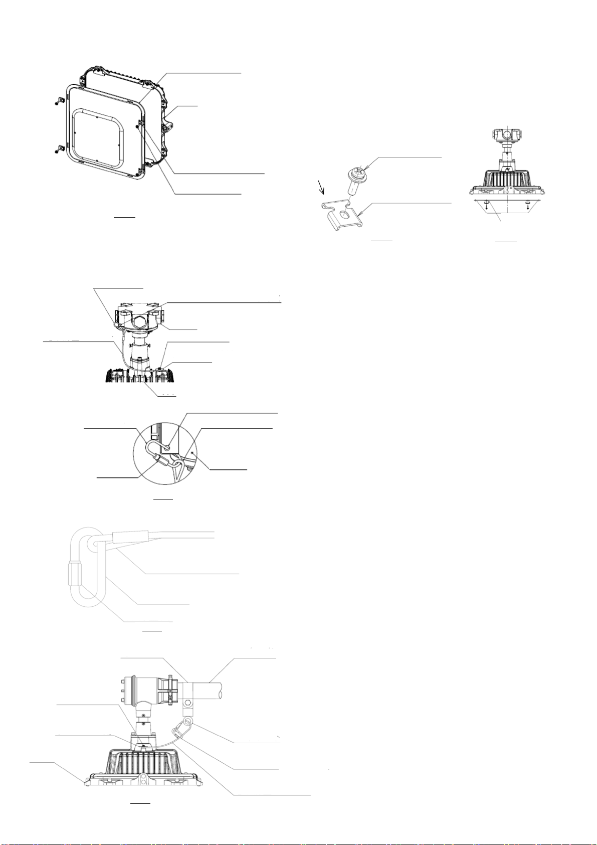
■Stanchion Type, Pole TypeB, TypeC
①
NB:
②
NB:
③
④
NB:
⑤
NB:
⑥
⑦
⑧
⑨
NB1:
NB2:
■Floodlight
①
②
③
④
NB1:
NB2:
The tilt of the fitting can be set within a range of 50° upwards to
60° downwards, and can be adjusted to the left and right within a
range of 45° each. See Fig.6 and 7.
Installation other than specified may cause explosion, fire, or
electric shock.
When adjusting the angle of the fitting or carrying the fixture,
be careful not to get your hands caught between the fitting
and the mounting legs.
Highway type have an up and down direction. Be sure to
install the lamp so that the installation direction sticker shown
in Fig.3 is on the top side of the lamp.
Connect the fitting power cable and pole junction box cable, and
after insulation treatment, screw the pole junction box lid onto
the pole junction box and tighten it completely.
Insert the cable of the pole junction box into the stand pole and
pull it out from the junction box. Insert the retaining screw into
the hole at the bottom of the pole tip and tighten.
Make sure that the fitting does not turn.
Pass the fitting power cable (black/white: power line, green:
ground line) through the pipe, screw the pipe into the holder
until the end, and fully tighten the suspension pipe rotation stop
screw on the fitting.
To adjust the angle of the fitting, loosen the hexagon socket head
bolts (4 locations) and adjust the angle.
See Fig.1 for mounting the junction box.
Connect the power cables (black/white: power wire, green:
ground wire) in the included junction box.
After tightening the five fixing screws on the pole junction box,
tighten the locking nut.
Make sure that the pole junction box does not rotate.
After connecting and insulating the power cables (black/white:
power wire, green: ground wire), attach the lid to the junction
box and tighten completely.
〜
The following applies only to the Stanchion Type
〜
Install the short nipple and junction box while referring to the
separate installation manual, "Short Nipple Installation Manual."
Please refer to Fig.1 for the mounting dimensions of the junction
box.
Completely fix the stand pole with the support bracket (not
supplied) and the specified junction box mounting screws.
Pass the power cable inside the pole (black/white: power wire,
green: ground wire) to the junction box and connect.
Waterproof the inside of the pole to prevent rainwater from
entering.
The installation direction of the device can be up to 15°,
assuming 0° is directly below.
As shown in Fig.6, securely attach the mounting legs of the device
to a horizontal mounting surface using M16 bolts (2pcs), nuts
(2pcs), spring washers (2pcs), and washers (2pcs). Wall mounting
is also possible.
Make sure that the pipe does not turn.
Insert the light power cable coming out of the pipe into the pole
junction box, then screw in the pipe.
After turning the pole junction box all the way, loosen it until the
stand pole can be attached. Fully tighten the pipe on the pole
junction box side with the anti-rotation screw.
灯具上側
④
①②
④
③
④
④
①
④
①
②③ ④
Fig. 2
Fig. 3
Fig. 4
Fig. 5 Fig. 6
Fig. 7 Fig. 8
5-Locking Screws
6
-
Locking Screws
Pole Junction Box
Pole Junction Box
Lid
Retaining Screw
Fitting
Retainer ①
Suspension Pipe
①②
Stand Pole
3
-
Locking Screws
Top of Lamp
Installation Direction Sticker
(Highway type only)
②
Support
(Not Supplied)
Short Nipple
Junction Box
⑥⑦⑧⑨
⑦
Fitting
Mounting
Legs
①
Scale
Plate
Scale Plate
Scale Plate
Mounting Legs
Mounting Legs
Hexagon Socket Head Bolt
Fitting
Fitting
Glass Surface
Junction Box
Cable and Protective Tube
φ18 Mounting
holes
φ18 Mounting
Long holes
①
⑤
⑤
②③⑤
⑧
- 2 -
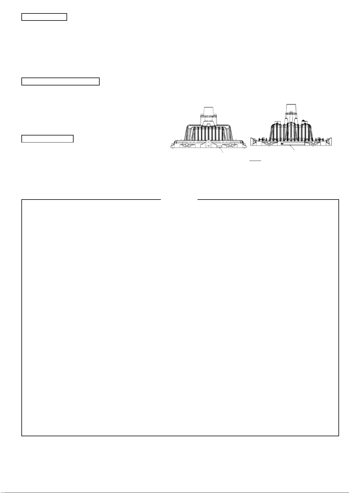
■Special Direct Mount Type
①
NB:
②
③
④
⑤
NB1:
NB2:
■Replacement demand
①
②
③
NB1:
NB2:
NB3:
■
Option 1: Guard
①
②
NB1:
NB2:
See Fig.1 for mounting the junction box.
Place the guard on the lamp house in Fig.14.
The tilt of the fitting can be set within a range of 60° upwards to
60° downwards, and can be adjusted left and right within a range
of 30° each. Please refer to Fig.10 and 11.
Installation other than specified may cause fire or electric
shock.
When adjusting the angle of the fitting or carrying the fixture,
be careful not to get your hands caught between the fitting
and the mounting legs.
Pipe thread diameter is G3/4.
Remove the existing fitting and pass the power cable coming out
of the fitting (black/white: power wire, green: ground wire)
through the existing pipe and existing junction Box.
Connect the power cable inside the existing junction box.
Screw the fitting into the existing suspension pipe.
Insert the guard mounting pieces(4 pieces) into the guard as
shown in Fig.15, and secure them to the fitting using M4
mounting screws (4pieces).
Regarding the mounting direction of the guard, as shown in
Fig.16, the guard protrusion is on the outside of the fitting.
Make sure the guard is securely fastened.
Before installing the fitting, make sure that there is no
corrosion in the existing piping (including junction box) before
installing the fixture.
If the product is to be used in a place where it will be splashed
with water, apply waterproof treatment to the joint between
the lamp fitting and the existing suspension pipe.
M12 bolt length should be up to 35mm.
Connect the power cables (black/white: power wire, green:
ground wire) in the included junction box.
To adjust the angle of the fitting, loosen the hexagon socket head
bolts (4 locations) and adjust the angle.
As shown in Fig.10, securely attach the mounting leg to a
horizontal mounting surface using M12 bolt (1 pc.), M8 bolt (2
pcs.), nuts (3 pcs.), spring washers (3 pcs.), and washers (3 pcs.).
Wall mounting is also possible.
①③
①
①
④⑤
Fig. 9 Fig. 10
Fig. 11 Fig. 12
Fig13
Fig. 14
Fig. 15
Fig. 16
Mounting
Legs
Glass
Fitting
φ14
Mounting Holes
2-φ10 Mounting
Long holes
Mounting
Legs
Fitting
④⑤
Cable and Protective Tube
Junction Box ②③
Fitting
Existing Junction Box(G3/4)
Cable Gland
Existing Suspension Pipe(G3/4) ①②
Cable
①②
Fitting
Guard ①②
4
-
Guard Mounting Pieces
②
Guard
Protrude
4-Mounting Screws ②
4
-
Guard Mounting Pieces
②
Place the guard mounting
pieces with its protrusions
on the inner side of the
Lamp house.
4-Mounting Screws ②
- 3 -
■
Option 2: Glare Cut Panel
①
②
NB1:
NB2:
■
Option 3: Fall prevention wire
1. For Direct Mount Type, Pipe Pendant Type, Bracket Type
①
NB:
②
NB:
③
NB:
④
2. For Stanction Type
①
NB:
②
③
④
After passing the fall prevention wire through the screw joint,
securely tighten the clamp using a tool.
Remove the screw attached to the fitting at the time of
shipment.
Do not use this screw.
As shown in Fig.21, pass the screw joint through one end of the
drop prevention wire, and then securely tighten the screw joint
clamp using a tool.
Using the screws supplied with the fall-prevention wire, attach
the fall-prevention wire, flat washer, and mounting screw to the
lamp fitting in that order.
As shown in Fig.22, pass the other end of the fall prevention wire
through the eyebolt (not supplied), etc., and then pass it through
the screw joint.
Using the mounting screws included with the fall prevention wire,
attach the fall prevention wire, washer, and mounting screw to
the fitting in this order.
Glare cut panel on the fitting as shown in Fig.17.
Remove the screw attached to the fitting at the time of
shipment.
Make sure the screws are securely fastened.
Pass the screw joint through the screw joint mounting hole in the
junction box.
There is directionality in the mounting direction of the screw
joint.
Do not use this screw.
Insert the panel mounting pieces(4 pieces) into the slits in the
panel as shown in Fig.18, and secure them to the fitting using M4
mounting screws(4 pieces).
Make sure the panel is securely fastened.
Please install the panel in the direction shown in Fig.19.
①
④
②④
②
①②
④
①
Fig.22
Fig.21
Fig.20
Fig. 17
Fig. 18
Fig. 19
Glare Cut Panel ①②
Fitting
4
-
Panel Mounting Pieces
②
4-Mounting Screws
4-Mounting Screws ②
4
-
Panel Mounting Pieces
②
Place the panel mounting
pieces with its protrusions
on the inner side of the
Lamp house.
Packing Pasted
(Silicon Rubber)
Screw Joint
Fall Prevention Wire
Junction Box
Mounting Screws
(Included)
Fitting
Screw Joint Mounting Hole
③
Screw Joint Mounting Hole
④
Junction Box
Fastener
Fall Prevention Wire ④
③④
Screw Joint
Fall Prevention Wire ②
Fastener ②
Screw Joint
Fitting
Fall Prevention Wire
②④
(Accessories)
(Accessories)
Screw Joint
Eyebolt
③
(Accessories)
(Accessories)
(not supplied)
(not supplied)
Hanging Band
Mounting Screws
①④
Washer
④
Stand/ Pole
②
Washer
②
②③
- 4 -
LED module is turned on by applying the rated voltage to the power cable of the product.
■
Inspection 1)
2) Prior to maintenance, be sure to turn off the power.
3) Carry out maintenance properly in accordance with the related law and regulations.
4) If a repair is needed, consult us.
1)
2) For disposal of the product, follow the regulations and rules of your local government.
When reordering, please let us know:
・Drawing or drawing No. for the delivered product
・Manufacturing lot number on the nameplate
1.
2. Prior to maintenance or inspection, be sure to turn off the power.
3. Confirm that the screws and bolts are fastened properly and tightly.
4. In the case of the stanchion type, be sure to provide a support at least 1500 mm above the bottom of the pole.
5. Can be used indoors and outdoors. However, it cannot be used in the following locations.
・Places where heat builds up, places with strong vibrations, places where corrosive gas is generated, places with constant high
temperature and humidity such as commercial bathrooms and saunas, places with constant low temperatures and condensation
such as freezers.
6. Cannot be used as a moving light.
7. In places where water is splashed, apply waterproof treatment to prevent water from entering the screw joint.
8.
9. The supply voltage variation should be within ±6% of the rating.
10. Close unused entries of the junctionl box with plugs (resin).
11. The ambient temperature should be within the range of -20°Cto +50°C. The use of the product out of this range may shorten
the service life.If the ambient temperature range is exceeded, the temperature protection function may dim the light.
The brightness will return to normal when the temperature returns to within the ambient temperature range.
12.
Be sure to ground the e uipment securely.
13. Prior to maintenance or inspection, be sure to turn off the power.
14. To prevent shortening of the service life and malfunction, avoid turning on the fitting in direct sunlight.
15. To avoid noise or malfunctioning, don't use a radio, television or wireless infrared remote control near the fitting.
16.
17.
18.
19.
20. Local replacement of lighting fixture parts such as the light source is not possible. Please contact our sales representative.
21. Do not look directly at the LED while it is lit. It can hurt your eyes.
Don’t open the front glass. The internal components such as the LED lamp become very hot. Don’t touch the LED lamp since a malfunction
or lighting failure might occur.
For white LED lamps, the luminescent color and brightness may vary with individual LEDs because of their nature. Also note that the rate
of attenuation with time varies with individual LED lamps.
How to Use
In cleaning the fitting, gently wipe with water or mild detergent. Don ’ t use thinner, benzene or alkaline detergent. Such
chemicals might cause discoloration or deterioration in uality and strength, resulting in a damage.
Disassembly and Disposal
If the above information is unavailable, give us any material showing the appearance of the product or details of the product specification
(dimensions, mounting interval, lamp type, etc.).
The product must be mounted on a sturdy wall surface or structure which is vibration-free and less susceptible to damage. Otherwise, it
might fall or be damaged.
For use in an unfavorable location (a very hot, cold or humid place or a place in which there is strong wind or vibration, a salt damage
environment or a dusty or corrosive gas atmosphere), a special countermeasure should be taken.
Please use e uipment installation within the installation range described in the range instruction manual. If the angle is out of the range,
an insulation failure or electric shock might result.
When installing the fitting, be sure to connect external wires inside a specified part of the fitting. Don't open any other part of the fitting
unless necessary.
In the period when the product is in use, never disassemble it.
Reordering
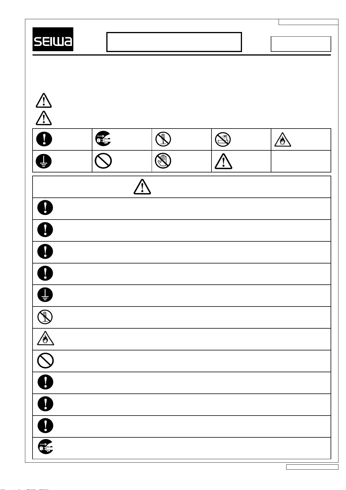
CAUTIONS
Fig.23
Lot Number
Nameplate
- 5 -
- Prior to use, please read the safety precautions and instruction manual thoroughly to use the product properly.
-
- Please keep the manual in a handy place for later reference.
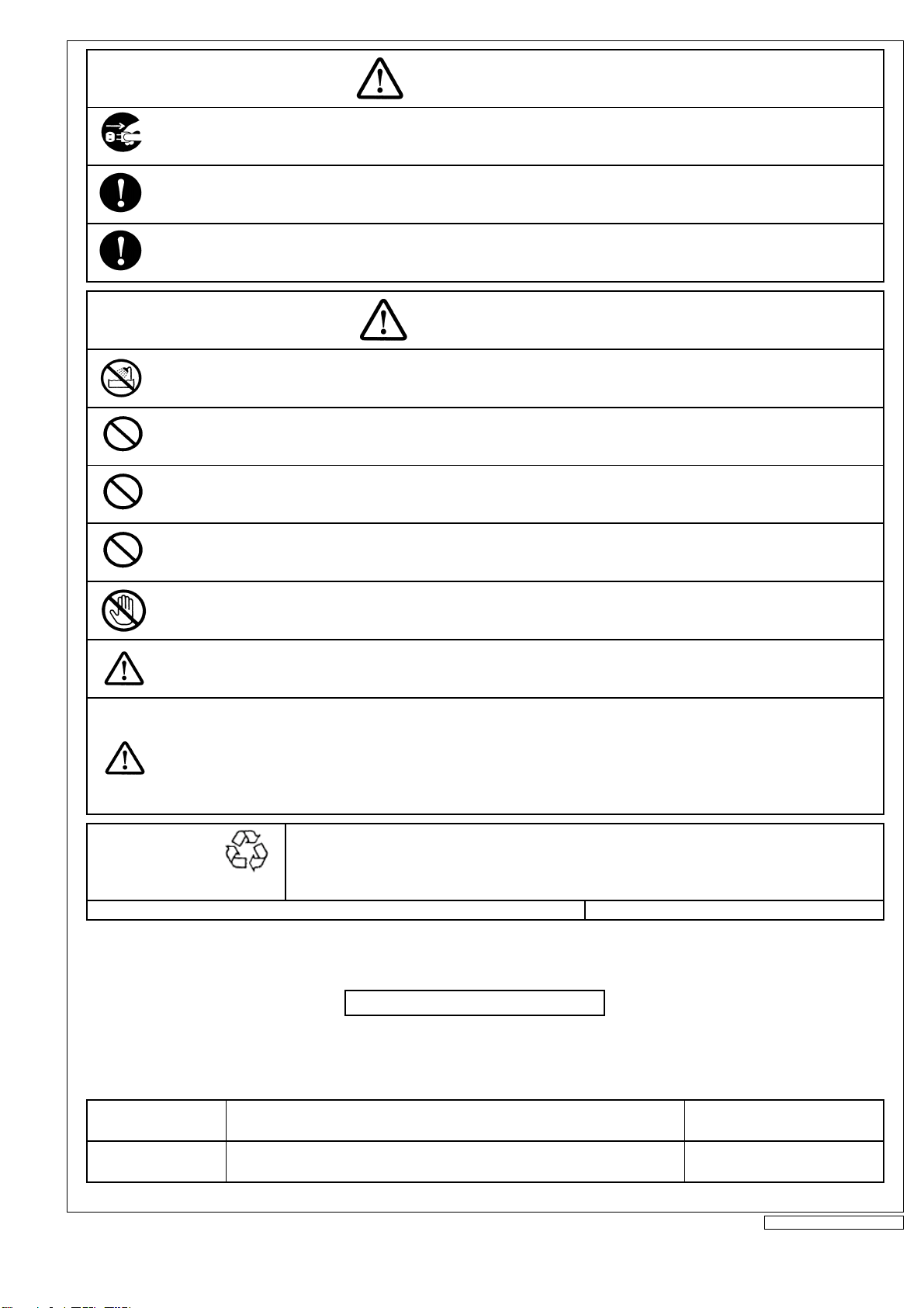
●The various marks have the following meanings:
Don’t cover the product with an inflammable material such as cloth or paper nor put anything in the product.
uch a material or thing might cause a fire.
The parts once removed for cleaning should be replaced properly according to the instruction manual.
An improperly placed part might cause the product to fall, resultng in an injury or property damage.
Be sure to turn
off the power.
Don’t use the product in a hazardous location where a flammable or explosive atmosphere such as a gaseous, steamy or
dusty atmosphere may exist. Use in such a location might cause an explosion or fire.
The ambient temperature should be within the operating temperature range specified in the instruction manual. If the
product should be used at a temperature higher than specified, an early lighting failure or malfunction might occur or a fire
might result.
If a product must be oriented in a specific manner for use, install it properly according to the marking on its body or the
instruction manual. Otherwise, a fire or electric shock might result.
Don’t touch.
In grounding work, be sure to follow the technical standards for electrical equipmentof your country. Inadequate grounding
might cause a fire or electric shock.
Be sure to
follow the
instructions.
Be sure to
ground.
For electrical connections, use crimp-type terminals, etc. to secure the connections and conduct insulation treatment. An
inadequate connection or inadequate insulation might cause an imperfect contact, leading to a fire or electric shock.
When leading the power cable into the product through a conduit or the like, waterproof the connection and joint
adequately to prevent water infiltration. Inadequate waterproofing might cause a fire or electric shock.
Don’t open LED lamp protective covers such as the front glass and glass globe.
Don’t touch an LED lamp, otherwise a malfunction or lighting failure might occur.
Don’t bend, twist or pull the power cable by force.
Inadequate handling of the cable might damage it and result in a fire or electric shock.
Before cleaning, be sure to turn off the power.
Otherwise, a fire or electric shock might result.
Be careful of
ignition.
After installing the product, be sure to hand the safety precautions and instruction manual over to the user of the product.
Caution
WARNING:
CAUTION:
Improper handling may lead to a human death or serious bodily injury.
Improper handling may lead to a bodily injury or property damage.
Disassembly &
conversion
prohibited.
Don’t use near
a water source.
Prohibited.
11E0000742F11
Safety Precautions
To be conserved
WARNING
Don’t convert the product.
Conversion might cause the product to fall or result in a fire or electric shock.
L照般6
- 1 /2 -
Please note that the above addresses and phone numbers may be changed.
Installation of the product should be carried out by a qualified person.
Installation by an unqualified person is legally prohibited.
Don’t use the product in a strong corrosive gas atmosphere which contains hydrochloric acid or chlorine gases or the like.
Use in a corrosive gas atmosphere might cause the product to corrode and fall, resulting in an injury.
The product should be mounted on a surface robust enough to support its weight, properly according to the instruction
manual. Improper installation might cause the product to fall or result in an electric shock or injury.
WARNING
Fax
To ensure brightness and safety, carry out periodical cleaning and inspection.
If used in an extended period without maintenance or inspection, a smoke, fire or electric shock might result.
For a product marked with a frequency, don’t use the product at a frequency other than 50 or 60 Hz (local power supply
frequency). Use at a wrong frequency might cause a fire.
If you continue to use the product in an abnormal condition (smoke, odor, etc.), a fire or electric shock might result. If you
detect an abnormality, immediately turn off the power switch. Confirm that the abnormal condition has been eliminated and
make a repair call.
Fax
2-19-6 Yanagibashi, Taito-ku, Tokyo 111-0052 Japan +81 3 5833 8971
+81 774 58 2034
+81 3 5833 8946
Head Office +81 774 55 8181
Phone
36 hinike, Terada, Joyo, Kyoto Pref. 610-0192 Japan
Tokyo Branch
SEIWA ELECTRIC MFG.CO., LTD.
Phone
CAUTION
A lighting fitting has a service life. A product which has been used for eight to ten years may have degraded internal parts
even if it looks normal. For safety and energy saving, we recommend you check and replace it. The LED module design life is
60,000 hours (different from the lighting fitting life) when used at an ambient temperature of 30°C, 10 hours per day, 3,000
hours per year. If used at a higher temperature or more hours per year, the life would be shortened. Have a specialist inspect
the product every three years. If used for an extended period without inspection, a smoke, fire, or electric shock might result.
Never touch LED light sources and their surroundings.
The light sources and their surroundings are very hot, so an accidental touch might cause a burn.
Don’t use the product at a voltage other than the rated voltage indicated on the nameplate.
Otherwise, breakage, fire or electric shock might result.
Any product not marked as a product for outdoor use should not be used outdoors or in a humid place or near a water
source. Its use in such a place might cause a fire or electric shock.
Ni-Cd
Ni-MH
L照般6
Recycling
Please bring used econdary batteries to the recycling station for effective use of precious
resources and global environment conservation.
JBRC
(Japan Portable Rechargeable Battery Recycling Center)
Phone +81 3 6403 5673
For further information on the product, contact any of our offices listed below (if you like to make an inquiry, let us know the model name
indicated on the product nameplate).
CONTACT DETAILS
- 2 /2 -
This manual suits for next models
2
Table of contents
Other Seiwa Lighting Equipment manuals


Popular Lighting Equipment manuals by other brands

SGM
SGM LB-100 user manual

HYBRYD
HYBRYD CRYSTAL LED Installation and maintenance manual

ELPRO
ELPRO BERT SQUADRA 130 installation instructions

Philips
Philips GreenPower TLED InstantFit Quick installation guide

Phottix
Phottix Kali50 user manual

Knightsbridge
Knightsbridge SPIKE5S Installation & maintenance manual


