SA00136004 Rev. 2.1 16
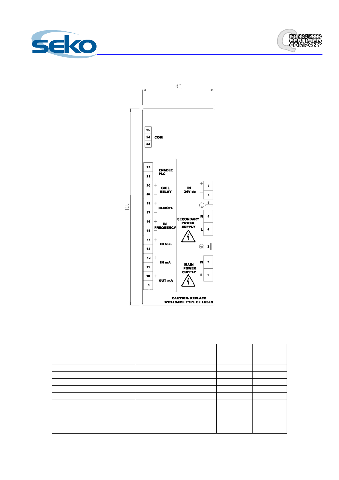
There is an output on the apparatus to allow an externally powered relay to be driven, which is triggered in alarm
conditions.
In the event of lack of power supply it is possible to adjust the stroke manually based on the indication provided by the
mechanical vernier index.
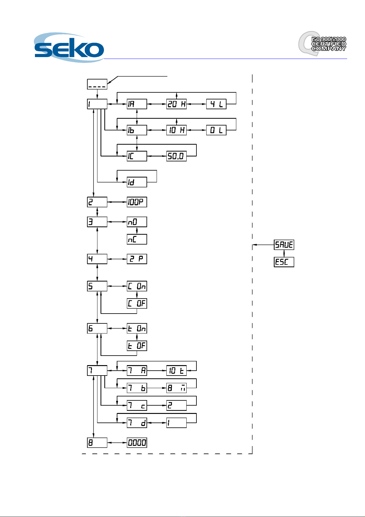
Optional actuator activation conditions
When the actuator is powered, it is possible to operate it using a panel switch, with normally closed or normally open logic,
which can be set during programming using the menu 3 and/or through an opto-isolated consent 100-240 Vac, which can
be set during programming using the menu 6. These settings are only present in automatic mode.
Therefore according to the programming it is possible to operate the actuator with the following signal combinations:
Activation of Remote Switch Operating Logic
Remote On Enable Plc On
Remote On
Remote Off
Remote Off Enable Plc On
If, based on the previous settings, the apparatus is blocked, Rappears flashing, while the percentage continues to be
displayed normally:
R 2
Deadband
This setting determines the sensitivity of the actuator; in practice, the actuator only immediately takes into consideration
input signal variations if they involve a variation of its position by a value greater than the deadband set; inside the
deadband, the actuator is insensitive for a certain amount of time to small input variations and its position remains stable.
The deadband mechanism automatically envisages internally a settling time for the input signals of 5 seconds; this means
that if the input signal is maintained at a certain value for over 5 seconds, even if this falls within the deadband, the
actuator will take it into consideration and will pe
form the relative movement.
The deadband is set by default to ±2% and can be adjusted from ±1% to ±10% by programming; the settling time for the
signals cannot be modified, and is fixed at 5 seconds.
This setting is only present in automatic mode.
ple: If a deadband of ±5% is set and you are at 50%, the system is not sensitive for 5 seconds to variations in the
field from 46% to 54%. If the input signal stays stable for more than 5 seconds at a certain value, even if this is included in
the deadband, the actuator carries out the requested movement anyway.
Splitting the adjustment field
It is possible to split the adjustment field so that the position variations determined by the input signals only affect a
percentage of the entire stroke of the actuator.
If, for example, we suppose that the input signals impose an adjustment of the system at 100%, by setting the splitting to
50%, the system will effectively go to 50% of the stroke and not to 100% (100% of 50%).
If the system is adjusted to 80% and 60% splitting is set, the actuator will go to 48% (80% of 60%).
When splitting is set, the 4/20 mA repetition signal will bring back the effective adjustment position. For example, if the
system is taken to 50% of the stroke due to a splitting setting, regardless of the adjustment percentage value, the output
will be settled on the value 12mA (50% on range 4-20mA).
Adjustment of motor parameters
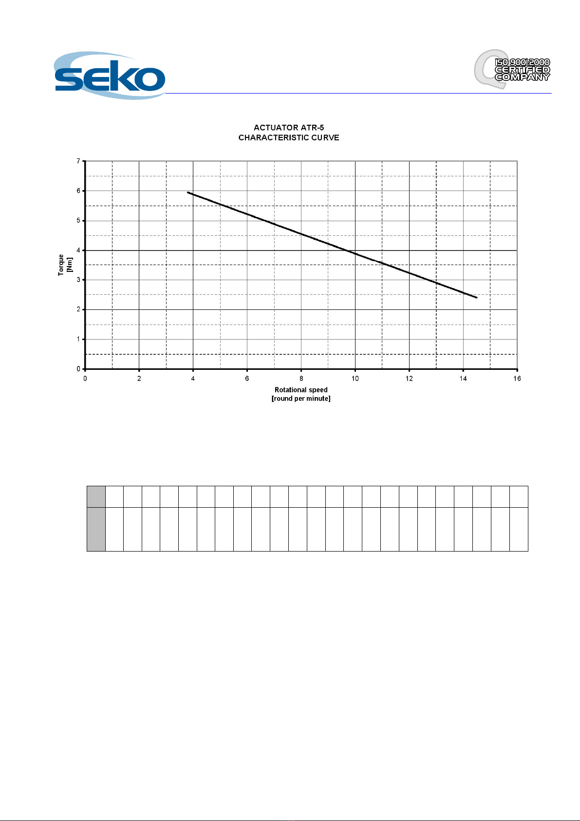
Torque adjustment
It is possible to vary the torque from the programming menu in the range 8-30.
The correspondence of these parameters to the speed in rpm is connected to the data shown in the relevant
Torque/Speed curves. A higher speed but a lower torque corresponds to the value 8, and vice versa, a lower speed but a
higher torque corresponds to the value 30.
Time Out parameter for unreached alarm position
It is possible to modify the Time Out parameter from 1 to 8 minutes, after which if the actuator has not reached its
envisaged position, the alarm is triggered.