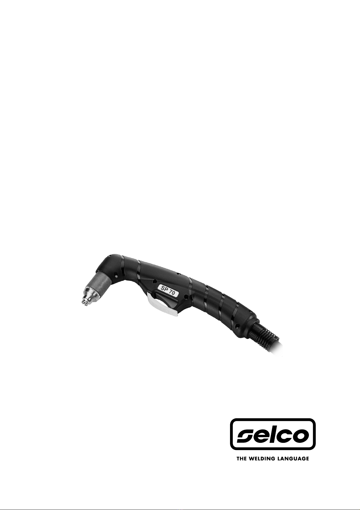
Sel SP 70 User manual

ISTRUZIONI PER L’USO
INSTRUCTION MANUAL
BETRIEBSANWEISUNG
MANUEL D’INSTRUCTIONS
INSTRUCCIONES DE USO
MANUAL DE INSTRUÇÕES
GEBRUIKSAANWIJZING
BRUKSANVISNING
BRUGERVEJLEDNING
BRUKSANVISNING
KÄYTTÖOHJEET
OΔΗΓΙΕΣ ΧΡΗΣΗΣ
SP 70

Cod. 91.08.314
Data 15/02/2018
Rev.
ITALIANO ................................................................................................................................................................................3
ENGLISH................................................................................................................................................................................13
DEUTSCH..............................................................................................................................................................................23
FRANÇAIS..............................................................................................................................................................................33
ESPAÑOL ...............................................................................................................................................................................43
PORTUGUÊS .........................................................................................................................................................................53
NEDERLANDS........................................................................................................................................................................63
SVENSKA................................................................................................................................................................................73
DANSK...................................................................................................................................................................................83
NORSK...................................................................................................................................................................................93
SUOMI ................................................................................................................................................................................103
ΕΛΛHNIKA..........................................................................................................................................................................113
5 Schema-Connettori, Diagram-Connectors, Schaltplan-Verbinder, Schéma-Connecteurs, Esquema-Conectores, Diagrama-
Conectores, Schema-Verbindingen, kopplingsschema-Kontaktdon, Oversigt-Konnektorer, Skjema-Skjøtemunnstykker,
Kytkentäkaavio-Liittimet, Διαγραμμα-Συνδετηρεσ .................................................................................................. 123
6 Lista ricambi, Spare parts list, Ersatzteilverzeichnis, Liste de pièces détachées, Lista de repuestos, Lista de peças de
reposição, Lijst van reserve onderdelen, Reservdelslista, Reservedelsliste, Liste over reservedeler, Varaosaluettelo,
καταλογοσ ανταλλακτικων ...................................................................................................................................... 124

ITALIANO
Ringraziamenti...
Vi ringraziamo della fiducia accordataci nell’aver scelto la QUALITA’, la TECNOLOGIA e l’AFFIDABILITA’ dei prodotti SELCO.
Per sfruttare le potenzialità e le caratteristiche del prodotto acquistato, vi invitiamo a leggere attentamente le seguenti istruzioni che
vi aiuteranno a conoscere al meglio il prodotto e ad ottenere i migliori risultati.
Prima di iniziare qualsiasi operazione siate sicuri di aver ben letto e compreso questo manuale. Non apportate modifiche e non ese-
guite manutenzioni non descritte. Per ogni dubbio o problema circa l’utilizzo della macchina, anche se qui non descritto, consultare
personale qualificato.
Questo manuale è parte integrante della unità o macchina e deve accompagnarla in ogni suo spostamento o rivendita.
È cura dell’utilizzatore mantenerlo integro ed in buone condizioni.
La SELCO s.r.l. si riserva il diritto di apportare modifiche in qualsiasi momento e senza alcun preavviso.
I diritti di traduzione, di riproduzione e di adattamento, totale o parziale e con qualsiasi mezzo (compresi le copie fotostatiche, i film
ed i microfilm) sono riservati e vietati senza l’autorizzazione scritta della SELCO s.r.l.
Quanto esposto è di vitale importanza e pertanto necessario affinchè le garanzie possano operare.
Nel caso l’operatore non si attenesse a quanto descritto, il costruttore declina ogni responsabilità.
DICHIARAZIONE DI CONFORMITA’ CE
La ditta
SELCO s.r.l. - Via Palladio, 19 - 35019 ONARA DI TOMBOLO (Padova) - ITALY
dichiara che l'apparecchio tipo SP 70
è conforme alle direttive EU: 2014/35/EU LOW VOLTAGE DIRECTIVE
2014/30/EU EMC DIRECTIVE
2011/65/EU CE MARKING DIRECTIVE
e che sono state applicate le norme: EN 60974-7
Ogni intervento o modifica non autorizzati dalla SELCO s.r.l. faranno decadere la validità di questa dichiarazione.
Onara di Tombolo (PADOVA) Selco s.r.l.
Lino Frasson
Chief Executive
3

INDICE
1 AVVERTENZE ................................................................................................................................................5
1.1 Ambiente di utilizzo...............................................................................................................................5
1.2 Protezione personale e di terzi...............................................................................................................5
1.3 Protezione da fumi e gas .......................................................................................................................6
1.4 Prevenzione incendio/scoppio ...............................................................................................................6
1.5 Prevenzione nell’uso delle bombole di gas.............................................................................................6
1.6 Protezione da shock elettrico.................................................................................................................6
1.7 Campi elettromagnetici ed interferenze .................................................................................................6
2 INSTALLAZIONE ............................................................................................................................................7
2.1 Messa in servizio....................................................................................................................................7
2.2 Uso della torcia......................................................................................................................................9
2.2.1 Inclinazione e velocità della torcia durante il taglio.............................................................................9
2.2.2 Forature..............................................................................................................................................9
2.2.3 Tagli circolari.......................................................................................................................................9
2.2.4 Consigli pratici....................................................................................................................................9
3 MANUTENZIONE ........................................................................................................................................10
4 CARATTERISTICHE TECNICHE.....................................................................................................................11
4
SIMBOLOGIA
Pericoli imminenti che causano gravi lesioni e comportamenti rischiosi che potrebbero causare gravi lesioni
Comportamenti che potrebbero causare lesioni non gravi o danni alle cose
Le note precedute da questo simbolo sono di carattere tecnico e facilitano le operazioni

5
1 AVVERTENZE
Prima di iniziare qualsiasi operazione siate sicuri di
aver ben letto e compreso questo manuale.
Non apportate modifiche e non eseguite manuten-
zioni non descritte.
Il produttore non si fa carico di danni a persone o cose, occorsi
per incuria nella lettura o nella messa in pratica di quanto scritto
in questo manuale.
Per ogni dubbio o problema circa l’utilizzo dell’im-
pianto, anche se qui non descritto, consultare per-
sonale qualificato.
1.1 Ambiente di utilizzo
Ogni impianto deve essere utilizzato esclusivamente per le
operazioni per cui è stato progettato, nei modi e nei campi
previsti in targa dati e/o in questo manuale, secondo le diret-
tive nazionali e internazionali relative alla sicurezza.
Un utilizzo diverso da quello espressamente dichiarato dal
costruttore è da considerarsi totalmente inappropriato e peri-
coloso e in tal caso il costruttore declina ogni responsabilità.
Questo apparecchio deve essere usato solo a scopo professio-
nale in un ambiente industriale.
Il costruttore non risponderà di danni provocati dall'uso del-
l'impianto in ambienti domestici.
L'impianto deve essere utilizzato in ambienti con temperatura
compresa tra i -10°C e i +40°C (tra i +14°F e i +104°F).
L'impianto deve essere trasportato e immagazzinato in
ambienti con temperatura compresa tra i -25°C e i +55°C (tra
i -13°F e i 131°F).
L'impianto deve essere utilizzato in ambienti privi di polvere,
acidi, gas o altre sostanze corrosive.
L'impianto deve essere utilizzato in ambienti con umidità relati-
va non superiore al 50% a 40°C (104°F).
L'impianto deve essere utilizzato in ambienti con umidità relati-
va non superiore al 90% a 20°C (68°F).
L'impianto deve essere utilizzato ad una altitudine massima sul
livello del mare di 2000m (6500 piedi).
1.2 Protezione personale e di terzi
Il processo di saldatura (taglio) è fonte nociva di
radiazioni, rumore, calore ed esalazioni gassose.
Indossare indumenti di protezione per proteggere
la pelle dai raggi dell’arco e dalle scintille o dal
metallo incandescente.
Gli indumenti utilizzati devono coprire tutto il
corpo e devono essere:
- integri e in buono stato
- ignifughi
- isolanti e asciutti
- aderenti al corpo e privi di risvolti
Utilizzare sempre calzature a normativa, resistenti e
in grado di garantire l'isolamento dall'acqua.
Utilizzare sempre guanti a normativa, in grado di
garantire l'isolamento elettrico e termico.
Sistemare una parete divisoria ignifuga per proteg-
gere la zona di saldatura (taglio) da raggi, scintille e
scorie incandescenti.
Avvertire le eventuali terze persone di non fissare
con lo sguardo la saldatura (taglio) e di proteggersi
dai raggi dell’arco o del metallo incandescente.
Utilizzare maschere con protezioni laterali per il
viso e filtro di protezione idoneo (almeno NR10 o
maggiore) per gli occhi.
Indossare sempre occhiali di sicurezza con schermi
laterali specialmente nell’operazione manuale o
meccanica di rimozione delle scorie di saldatura
(taglio).
Non utilizzare lenti a contatto!!!
Utilizzare cuffie antirumore se il processo di saldatu-
ra (taglio) diviene fonte di rumorosità pericolosa.
Se il livello di rumorosità supera i limiti di legge,
delimitare la zona di lavoro ed accertarsi che le
persone che vi accedono siano protette con cuffie
o auricolari.
L'impianto non deve essere sottoposto ad alcun tipo di modifica.
L'esclusione dei dispositivi di protezione sulle unità di avanza-
mento del filo è estremamente pericoloso e solleva il costrut-
tore da ogni responsabilità su danni a cose e persone.
Tenere sempre i pannelli laterali chiusi durante le operazioni
di saldatura (taglio).
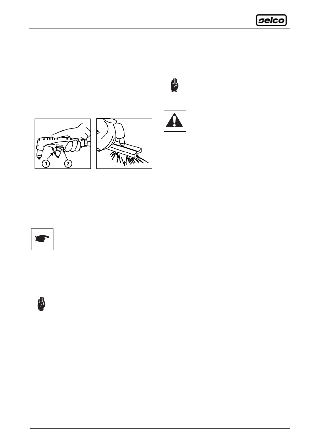
Tenere la testa lontano dalla torica PLASMA. Il flus-
so di corrente in uscita può provocare seri danni
alle mani, al viso e agli occhi.
Evitare di toccare i pezzi appena saldati, l'elevato
calore potrebbe causare gravi ustioni o scottature.
Mantenere tutte le precauzioni precedentemente descritte
anche nelle lavorazioni post saldatura in quanto, dai pezzi lavo-
rati che si stanno raffreddando, potrebbero staccarsi scorie.
Assicurarsi che la torcia si sia raffreddata prima di eseguire
lavorazioni o manutenzioni.
Provvedere ad un’attrezzatura di pronto soccorso.
Non sottovalutare scottature o ferite.
Prima di lasciare il posto di lavoro, porre in sicu-
rezza l'area di competenza in modo da impedire
danni accidentali a cose o persone.

6
1.3 Protezione da fumi e gas
• Fumi, gas e polveri prodotti dal processo di saldatura (taglio)
possono risultare dannosi alla salute.
I fumi prodotti durante il processo di saldatura (taglio) posso-
no, in determinate circostanze, provocare il cancro o danni al
feto nelle donne in gravidanza.
• Tenere la testa lontana dai gas e dai fumi di saldatura
(taglio).
• Prevedere una ventilazione adeguata, naturale o forzata, nella
zona di lavoro.
• In caso di aerazione insufficiente utilizzare maschere dotate
di respiratori.
• Nel caso di saldature (tagli) in ambienti angusti è consigliata
la sorveglianza dell’operatore da parte di un collega situato
esternamente.
• Non usare ossigeno per la ventilazione.
• Verificare l'efficacia dell'aspirazione controllando periodica-
mente l'entità delle emissioni di gas nocivi con i valori ammes-
si dalle norme di sicurezza.
• La quantità e la pericolosità dei fumi prodotti è riconducibile
al materiale base utilizzato, al materiale d'apporto e alle even-
tuali sostanze utilizzate per la pulizia e lo sgrassaggio dei pezzi
da saldare (tagliare). Seguire attentamente le indicazioni del
costruttore e le relative schede tecniche.
• Non eseguire operazioni di saldatura (taglio) nei pressi di
luoghi di sgrassaggio o verniciatura.
Posizionare le bombole di gas in spazi aperti o con un buon
ricircolo d’aria.
1.4 Prevenzione incendio/scoppio
• Il processo di saldatura (taglio) può essere causa di incendio
e/o scoppio.
• Sgomberare dalla zona di lavoro e circostante i materiali o gli
oggetti infiammabili o combustibili.
I materiali infiammabili devono trovarsi ad almeno 11 metri
(35 piedi) dall'ambiente di saldatura (taglio) o devono essere
opportunamente protetti.
Le proiezioni di scintille e di particelle incandescenti possono
facilmente raggiungere le zone circostanti anche attraverso
piccole aperture. Porre particolare attenzione nella messa in
sicurezza di cose e persone.
• Non eseguire saldature (tagli) sopra o in prossimità di reci-
pienti in pressione.
• Non eseguire operazioni di saldatura o taglio su recipienti o
tubi chiusi.
Porre comunque particolare attenzione nella saldatura (taglio)
di tubi o recipienti anche nel caso questi siano stati aperti,
svuotati e accuratamente puliti. Residui di gas, carburante,
olio o simili potrebbe causare esplosioni.
• Non saldare (tagliare) in atmosfera contenente polveri, gas o
vapori esplosivi.
• Accertarsi, a fine saldatura (taglio), che il circuito in tensione
non possa accidentalmente toccare parti collegate al circuito
di massa.
• Predisporre nelle vicinanze della zona di lavoro un’ attrezza-
tura o un dispositivo antincendio.
1.5 Prevenzione nell’uso delle bombo-
le di gas
• Evitare che le bombole entrino in contatto con fiamme libere,
con archi elettrici, con torce o pinze porta elettrodo, con le
proiezioni incandescenti prodotte dalla saldatura (taglio).
• Tenere le bombole lontano dai circuiti di saldatura (taglio) e
dai circuiti di corrente in genere.
• Tenere la testa lontano dal punto di fuoriuscita del gas quando
si apre la valvola della bombola.
• Non eseguire mai saldature (tagli) su una bombola di gas in
pressione.
• Non collegare mai una bombola di aria compressa diretta-
mente al riduttore della macchina!
La pressione potrebbe superare la capacità del riduttore che
quindi potrebbe esplodere!
1.6 Protezione da shock elettrico
• Uno shock da scarica elettrica può essere mortale.
• Non toccare contemporaneamente due torce o due pinze
portaelettrodo.
Interrompere immediatamente le operazioni di saldatura
(taglio) se si avverte la sensazione di scossa elettrica.
Il dispositivo di innesco e stabilizzazione dell’arco è
progettato per il funzionamento a guida manuale o
meccanica.
1.7 Campi elettromagnetici ed interferenze
Il passaggio della corrente di saldatura (taglio) attraverso i cavi
interni ed esterni all'impianto, crea un campo elettromagnetico
nelle immediate vicinanze dei cavi di saldatura (taglio) e dell'im-
pianto stesso.
I campi elettromagnetici possono avere effetti (ad oggi scono-
sciuti) sulla salute di chi ne subisce una esposizione prolungata.
I campi elettromagnetici possono interferire con altre appa-
recchiature quali pace-maker o apparecchi acustici.
I portatori di apparecchiature elettroniche vitali
(pace-maker) devono consultare il medico prima di
avvicinarsi alle operazioni di saldatura ad arco o di
taglio al plasma.

Cavi di saldatura e taglio
Per minimizzare gli effetti dei campi elettromagnetici, seguire le
seguenti regole:
- Arrotolare insieme e fissare, dove possibile, cavo massa e cavo
potenza.
- Evitare di arrotolare i cavi di saldatura intorno al corpo.
- Evitare di frapporsi tra il cavo di massa e il cavo di potenza
(tenere entrambi dallo stesso lato).
- I cavi devono essere tenuti più corti possibile e devono essere
posizionati vicini e scorrere su o vicino il livello del suolo.
- Posizionare l'impianto ad una certa distanza dalla zona di
saldatura.
- I cavi devono essere posizionati lontano da eventuali altri cavi
presenti.
Collegamento equipotenziale
Il collegamento a massa di tutti i componenti metallici nell’
impianto di saldatura (taglio) e nelle sue vicinanze deve essere
preso in considerazione.
Rispettare le normative nazionali riguardanti il collegamento
equipotenziale.
Messa a terra del pezzo in lavorazione
Dove il pezzo in lavorazione non è collegato a terra, per motivi
di sicurezza elettrica o a causa della dimensione e posizione,
un collegamento a massa tra il pezzo e la terra potrebbe ridurre
le emissioni.
Bisogna prestare attenzione affinché la messa a terra del pezzo
in lavorazione non aumenti il rischio di infortunio degli utilizza-
tori o danneggi altri apparecchi elettrici.
Rispettare le normative nazionali riguardanti la messa a terra.
Schermatura
La schermatura selettiva di altri cavi e apparecchi presenti nell’
area circostante può alleviare i problemi di interferenza.
La schermatura dell’intero impianto di saldatura (taglio) può
essere presa in considerazione per applicazioni speciali.
2 INSTALLAZIONE
L’installazione può essere effettuata solo da per-
sonale esperto ed abilitato dal produttore.
Per l’installazione assicurarsi che il generatore
sia scollegato dalla rete di alimentazione.
2.1 Messa in servizio
Prima di iniziare il lavoro è necessario eseguire i seguenti con-
trolli ed operazioni:
1. Controllare che il generatore sia spento.
2. Controllare che la torcia sia efficiente in tutte le sue parti.
Il corretto assemblaggio del corpo torcia prevede la sequenza
di montaggio dei seguenti componenti: 1-2-3-4-5.
3. Controllare lo stato d'efficienza del diffusore aria (2), che
deve sempre presentare i fori di accesso liberi da occlusioni;
l'uso del diffusore aria difettoso può causare un eccessivo
riscaldamento con conseguente danneggiamento dei com-
poneti del corpo torcia.
4. A torcia assemblata, controllare che avvitando l'ugello ester-
no (4) al corpo torcia si disinserisca l'allarme corrispondente
sul generatore; verificare infine che, svitando l'ugello, tale
allarme intervenga; questi controlli vanno effettuati a gene-
ratore acceso ponendo estrema attenzione a non premere il
pulsante torcia durante le operazioni sopra descritte.
5. L'aria compressa utilizzata deve essere filtrata e mantenuta
ad elevato grado di purezza; aria umida, oli ed altri agenti
contaminanti devono essere rimossi facendo uso di opportu-
ni essicatori e filtri antiolio. La torcia è così predisposta per le
operazioni di taglio.
In ogni caso è necessario seguire anche quanto prescritto dal
manuale di istruzioni del generatore soprattutto nei paragra-
fi “Avvertenze", "Allacciamento" e “Manutenzione".
7

Collegamento per il taglio al plasma
- Collegare la torcia (1) sull’attacco (2), prestando particolare
attenzione nell’avvitare completamente la ghiera di fissaggio.
- Verificare la presenza di tutte le componenti del corpo torcia
e il loro fissaggio.
- Collegare il connettore (3) del cavo della pinza di massa alla
presa positiva (+) (4) del generatore.
- Inserire la spina (3) e ruotare in senso orario fino al completo
fissaggio delle parti.
- Posizionare la pinza di massa sul pezzo da tagliare e assicurar-
si che vi sia un buon contatto elettrico.
- Avvitare il raccordo (5) sul riduttore di pressione (6).
- Innestare il tubo (7) sul raccordo (5).
- La pressione deve garantire almeno 5 bar con portata minima
pari a 185 litri al minuto.
- Inserire la spina nella presa da 400V.
- Accendere il generatore controllando il corretto funziona-
mento del led di segnalazione.
- Premere il pulsante torcia o il pulsante test gas per far fluire il
gas durante le operazioni di taratura.
- Sollevare la manopola di regolazione (8) del riduttore (6).
- Ruotarla fino a leggere 5 bar sul manometro (9).
8

9
2.2 Uso della torcia
Accendere il generatore controllando il corretto funzionamento
del led di segnalazione. Qualora le parti della torcia fossero
mancanti o mai assemblate, oppure la pressione del circuito
dell'aria compressa risultasse insufficiente o mancante, rispetti-
vamente i led segnaleranno le anomalie e il funzionamento del
generatore risulterà inibito fino al momento in cui le condizioni
normali operative verranno ripristinate.
"Consultare la sezione "Messa in servizio" del manuale d'uso del
generatore".
2.2.1 Inclinazione e velocità della torcia durante il
taglio
- Impugnare la torcia e sollevare la levetta di protezione (1).
- Premere momentaneamente il pulsante torcia (2) fino a
generare l'arco pilota; togliere il comando verificando il cor-
retto funzionamento della macchina attraverso il pannello di
visualizzazione.
Si consiglia di non mantenere inutilmente l'arco pilota acceso
in aria in modo da evitare l'usura dell'elettrodo e dell'ugello;
in ogni caso sarà l'apparecchiatura stessa a spegnere l'arco
pilota dopo circa 6 secondi.
Avvicinare la torcia al pezzo, iniziare a tagliare
avanzando in modo costante.
La torcia va mantenuta generalmente perpendicolare al pezzo
durante tutte le fasi di taglio; ovviamente, qualora si desideri
l'esecuzione di smussi o tagli inclinati, si dovrà dare al corpo
torcia l'inclinazione appropriata.
La velocità dev'essere regolata in modo che la fuoriuscita dell'ar-
co al di sotto del pezzo sia perpendicolare (sono accettabili 5-10
gradi di inclinazione).
Si consiglia una partenza a velocità ridotta per
evitare spruzzi di materiali che potrebbero dan-
neggiare la cappa.
2.2.2 Forature
In alcuni casi si rende necessaria la foratura dei materiali utiliz-
zando il taglio al plasma. E' importante segnalare che questa
modalità operativa aumenta l'usura delle parti soggette a consu-
mo e può essere causa di spruzzi il cui ritorno può diventare
dannoso per l'operatore e per l'integrità della torcia stessa
soprattutto se si opera su lamiere con spessori superiori ai 5mm.
Si consiglia, perciò, di eseguire le partenze inclinan-
do lateralmente la torcia in modo da dirigere gli
spruzzi verso l'esterno della zona di taglio evitando
di danneggiare e surriscaldare il corpo torcia.
Rimuovere immediatamente eventuale materiale
accumulato sulla cappa o sul cappuccio ceramico.
Attenzione: il taglio al plasma è un processo con
grande apporto termico che porta ad altissima
temperatura sia il pezzo da tagliare che la parte
terminale della torcia.
2.2.3 Tagli circolari
Per la preparazione di flange e l'apertura di fori vi è la possibilità
di utilizzare un compasso dotato di testa rotante con movimen-
to su rotelle.
Kit compasso (73.04.010)
Kit per smussare (73.04.011)
2.2.4 Consigli pratici
Si consiglia di accendere l'arco pilota, fuori dal pezzo per poi
avvicinarsi fino all'innesco dell'arco di taglio; innescare l'arco di
taglio ripetutamente e direttamente a contatto del pezzo provo-
ca un aumento di temperatura nel corpo torcia.
Evitare di spegnere il generatore prima della fine del flusso di
raffreddamento post taglio per evitare il surriscaldamento dei
componenti della torcia.

10
3 MANUTENZIONE
Nella torcia SP 70 l’innesco dell’arco pilota avviene per allon-
tanamento pneumatico dell’elettrodo dalla cappa; nell’opera-
zione si creano delle zone ossidate sui due componenti, che
possono dare problemi di innesco.
L'efficienza e la durata dell'elettrodo non è quindi determinata dal
tempo di taglio ma anche dal numero di inneschi di arco pilota
effettuati. Si consiglia di sostituire l'elettrodo prima del totale con-
sumo dell'inserto in tungsteno presente nella sua punta.
La cappa ha in genere una vita media simile a quella dell'elet-
trodo e va sostituito quando presenta un foro irregolare e di dia-
metro maggiorato rispetto a quello nominale (ciò può provocare
tagli obliqui e di cattiva qualità).
Elettrodo e cappa vanno cambiati contemporaneamente per
prolungare la durata di entrambi.
Lavorare con elettrodo e cappa troppo rovinati può creare
danni al corpo torcia.
Bisogna porre particolare attenzione al fissaggio di elettrodo e
cappa per non danneggiare irreparabilmente la torcia.
L’impianto deve essere sottoposto ad una manu-
tenzione ordinaria secondo le indicazioni del
costruttore.
L’eventuale manutenzione deve essere eseguita esclusivamente
da personale qualificato.
L’impianto non deve essere sottoposto ad alcun tipo di modifica.
Togliere l'alimentazione all'impianto prima di
ogni intervento!
Controllare le connessioni elettriche e tutti i cavi
di collegamento.
Per la manutenzione o la sostituzione dei componenti delle
torce, della pinza portaelettrodo e/o del cavo massa:
Controllare la temperatura dei componenti ed
accertarsi che non siano surriscaldati.
Utilizzare sempre guanti a normativa.
Utilizzare chiavi ed attrezzi adeguati.
In mancanza di detta manutenzione, decadranno tutte le
garanzie e comunque il costruttore viene sollevato da qual-
siasi responsabilità.

11
4 CARATTERISTICHE TECNICHE
Fattore di utilizzo (x=50%) 70 A
Pressione aria Cutting 5.0÷5.5 bar
Gouging 4.0÷4.5 bar
Tipo di raffreddamento Aria/Azoto
Portata 185 l/min
Tipo di innesco LIFT
Corrente di arco pilota 12-15 A
Diametro foro cappa 0.8÷1.1 mm
Lunghezza 6 m
Peso -

12

ENGLISH
Thanks...
We wish to thank you for choosing the QUALITY, TECHNOLOGY and RELIABILITY of SELCO products.
In order to take advantage of all functions and features of the equipment you have purchased, we recommend that you should read
the following instructions carefully: they will help you to better know the product and to achieve the best possible results.
Before performing any operation on the machine, make sure that you have thoroughly read and understood the contents of this
booklet. Do not perform modifications or maintenance operations which are not prescribed.
Do consult qualified personnel for any doubt or problem concerning the use of the machine, even if not described herein,.
This booklet is an integral part of the equipment and must accompany it when it changes location or is sold to third parties.
The user shall be responsible for keeping this booklet intact and legible.
SELCO s.r.l. reserves the right to modify this booklet at any time without notice.
All rights of translation and total or partial reproduction by any means whatsoever (including photocopy, film, and microfilm) are
reserved and reproduction is prohibited without the explicit written consent of SELCO s.r.l.
The directions provided herewith are of vital importance and therefore necessary to ensure the warranties.
The manufacturer accepts no liability in case of misuse or non-application of the directions by the users.
CE - DECLARATION OF CONFORMITY
Company
SELCO s.r.l. - Via Palladio, 19 - 35019 ONARA DI TOMBOLO (Padova) - ITALY
hereby declares that the equipment: SP 70
conforms to the EU directives: 2014/35/EU LOW VOLTAGE DIRECTIVE
2014/30/EU EMC DIRECTIVE
2011/65/EU CE MARKING DIRECTIVE
and that following harmonized standards have been duly applied: EN60974-7
Any operation or modification that has not been previously authorized by SELCO s.r.l. will invalidate this certificate.
Onara di Tombolo (PADOVA) Selco s.r.l.
Lino Frasson
Chief Executive
13

14
INDEX
SYMBOLS
Imminent danger of serious body harm and dangerous behaviours that may lead to serious body harm
Important advice to be followed in order to avoid minor injuries or damage to property
Technical notes to facilitate operations
1 WARNING ...................................................................................................................................................15
1.1 Work environment...............................................................................................................................15
1.2 User's and other persons' protection.....................................................................................................15
1.3 Protection against fumes and gases ......................................................................................................16
1.4 Fire/explosion prevention.....................................................................................................................16
1.5 Prevention when using gas cylinders ....................................................................................................16
1.6 Protection from electrical shock...........................................................................................................16
1.7 Electromagnetic fields & interferences..................................................................................................16
2 INSTALLATION.............................................................................................................................................17
2.1 Commissioning ....................................................................................................................................17
2.2 Using the torch....................................................................................................................................19
2.2.1 Inclination and speed of the torch during cutting..............................................................................19
2.2.2 Puncturing ........................................................................................................................................19
2.2.3 Circular cutting .................................................................................................................................19
2.2.4 Practical advice.................................................................................................................................19
3 MAINTENANCE............................................................................................................................................20
4 TECHNICAL SPECIFICATIONS .....................................................................................................................21

15
1 WARNING
Before performing any operation on the machine,
make sure that you have thoroughly read and
understood the contents of this booklet.
Do not perform modifications or maintenance
operations which are not prescribed.
The manufacturer cannot be held responsible for damages to
persons or property caused by misuse or non-application of the
contents of this booklet by the user.
Please consult qualified personnel if you have any
doubts or difficulties in using the equipment.
1.1 Work environment
• All equipment shall be used exclusively for the operations for
which it was designed, in the ways and ranges stated on the
rating plate and/or in this booklet, according to the national
and international directives regarding safety. Other uses than
the one expressly declared by the manufacturer shall be con-
sidered totally inappropriate and dangerous and in this case
the manufacturer disclaims all responsibility.
• This equipment shall be used for professional applications
only, in industrial environments.
The manufacturer shall not be held responsible for any dam-
ages caused by the use of the equipment in domestic environ-
ments.
• The equipment must be used in environments with a tem-
perature between -10°C and +40°C (between +14°F and
+104°F).
The equipment must be transported and stored in envi-
ronments with a temperature between -25°C and +55°C
(between -13°F and 131°F).
• The equipment must be used in environments free from dust,
acid, gas or any other corrosive substances.
• The equipment shall not be used in environments with a rela-
tive humidity higher than 50% at 40°C (104°F).
The equipment shall not be used in environments with a rela-
tive humidity higher than 90% at 20°C (68°F).
• The system must not be used at an higher altitude than 2,000
metres (6,500 feet) above sea level.
1.2 User's and other persons' protection
The welding (cutting) process is a noxious source of
radiation, noise, heat and gas emissions.
Wear protective clothing to protect your skin from
the arc rays, sparks or incandescent metal.
Clothes must cover the whole body and must be:
- intact and in good conditions
- fireproof
- insulating and dry
- well-fitting and without cuffs or turn-ups
Always use regulation shoes that are strong and
ensure insulation from water.
Always use regulation gloves ensuring electrical and
thermal insulation.
Position a fire-retardant shield to protect the sur-
rounding area from rays, sparks and incandescent
slags.
Advise any person in the area not to stare at the arc
or at the incandescent metal and to get an adequate
protection.
Wear masks with side face guards and a suitable
protection filter (at least NR10 or above) for the
eyes.
Always wear safety goggles with side guards, espe-
cially during the manual or mechanical removal of
welding (cutting) slag.
Do not wear contact lenses!.
Use headphones if dangerous noise levels are
reached during the welding (cutting).
lf the noise level exceeds the limits prescribed by
law, delimit the work area and make sure that any-
one getting near it is protected with headphones or
earphones.
• The systems must not undergo any kind of modification.
Bypassing the protection devices fitted on wire feed units is
extremely dangerous and releases the manufacturer from any
responsibility in respect of damages to either people or property.
• Always keep the side covers closed while welding (cutting).
Keep your head away from the PLASMA torch. The
outcoming electric arc can seriously damage your
hands, face and eyes.
Avoid touching items that have just been welded:
the heat could cause serious burning or scorching.
• Follow all the precautions described above also in all opera-
tions carried out after welding since slag may detach from the
items while they are cooling off.
• Check that the torch is cold before working on or maintaining it.
Keep a first aid kit ready for use.
Do not underestimate any burning or injury.
Before leaving work, make the area safe, in order to
avoid accidental damage to people or property.

16
1.3 Protection against fumes and gases
• Fumes, gases and powders produced during the welding (cut-
ting) process can be noxious for your health.
Under certain circumstances, the fumes caused by welding
(cutting) can cause cancer or harm the foetus of pregnant
women.
• Keep your head away from any welding (cutting) gas and
fumes.
• Provide proper ventilation, either natural or forced, in the
work area.
• In case of poor ventilation, use masks and breathing apparatus.
• In case of welding (cutting) in extremely small places the work
should be supervised by a colleague standing nearby outside.
• Do not use oxygen for ventilation.
• Ensure that the fumes extractor is working by regularly check-
ing the quantity of harmful exhaust gases versus the values
stated in the safety regulations.
• The quantity and the danger level of the fumes depends on
the parent metal used, the filler metal and on any substances
used to clean and degrease the pieces to be welded (cut-
ted). Follow the manufacturer's instructions together with the
instructions given in the technical sheets.
• Do not perform welding (cutting) operations near degreasing
or painting stations.
Position gas cylinders outdoors or in places with good ventila-
tion.
1.4 Fire/explosion prevention
• The welding (cutting) process may cause fires and/or explo-
sions.
• Clear the work area and the surrounding area from any flam-
mable or combustible materials or objects.
Flammable materials must be at least 11 metres (35 feet) from
the welding (cutting) area or they must be suitably protected.
Sparks and incandescent particles might easily be sprayed
quite far and reach the surrounding areas even through min-
ute openings. Pay particular attention to keep people and
property safe.
• Do not perform welding (cutting) operations on or near con-
tainers under pressure.
• Do not perform welding or cutting operations on closed con-
tainers or pipes.
Pay particular attention during welding (cutting) operations on
pipes or containers even if these are open, empty and have
been cleaned thoroughly. Any residue of gas, fuel, oil or simi-
lar materials might cause an explosion.
• Do not weld (cut) in places where explosive powders, gases or
vapours are present.
• When you finish welding (cutting), check that the live circuit
cannot accidentally come in contact with any parts connected
to the earth circuit.
• Position a fire-fighting device or material near the work area.
1.5 Prevention when using gas cylinders
• Keep cylinders away from naked flames, electric arcs, torches
or electrode guns and incandescent material sprayed by weld-
ing (cutting).
• Keep cylinders away from welding (cutting) circuits and elec-
trical circuits in general.
• Keep your head away from the gas outlet when opening the
cylinder valve.
• Never perform welding (cutting) operations on a pressurized
gas cylinder.
• A compressed air cylinder must never be directly coupled
to the machine pressure reducer. Pressure might exceed the
capacity of the reducer which could consequently explode.
1.6 Protection from electrical shock
• Electric shocks can kill you.
• Do not touch two torches or two electrode holders at the
same time.
lf you feel an electric shock, interrupt the welding (cutting)
operations immediately.
The arc striking and stabilizing device is designed
for manual or mechanically guided operation.
1.7 Electromagnetic fields &
interferences
• The welding (cutting) current passing through the internal and
external system cables creates an electromagnetic field in the
proximity of the welding (cutting) cables and the equipment
itself.
• Electromagnetic fields can affect the health of people who
are exposed to them for a long time (the exact effects are still
unknown).
Electromagnetic fields can interfere with some equipment like
pacemakers or hearing aids.
Persons fitted with pacemakers must consult their
doctor before undertaking arc welding or plasma
cutting operations.

17
Welding and cutting cables
To minimise the effects of electromagnetic fields follow the fol-
lowing instructions:
- Where possible, collect and secure the earth and power
cables together.
- Never coil the welding cables around your body.
- Do not place your body in between the earth and power
cables (keep both on the same side).
- The cables must be kept as short as possible, positioned as
close as possible to each other and laid at or approximately at
ground level.
- Position the equipment at some distance from the welding
area.
- The cables must be kept away from any other cables.
Earthing connection
The earth connection of all the metal components in the weld-
ing (cutting) equipment and in the close aerea must be taken in
consideration.
The earthing connection must be made according to the local
regulations.
Earthing the workpiece
When the workpiece is not earthed for electrical safety reasons
or due to its size and position, the earthing of the workpiece
may reduce the emissions. It is important to remember that
the earthing of the workpiece should neither increase the risk
of accidents for the user nor damage other electric equipment.
The earthing must be made according to the local regulations.
Shielding
The selective shielding of other cables and equipment present
in the surrounding area may reduce the problems due to elec-
tromagnetic interference. The shielding of the entire welding
(cutting) equipment can be taken in considered for special
applications.
2 INSTALLATION
Installation should be performed only by expert
personnel authorised by the manufacturer.
During installation, ensure that the power source
is disconnected from the mains.
2.1 Commissioning
Before starting work, it is necessary to carry out the following
checks and work:
1. Check that the generator is turned off.
2. Check that all the parts of the torch are working. For the
various parts that make up the torch body, the sequence of
correct assembly is 1-2-3-4-5.
3. Check that the air diffuser, or "swirl-bush" (2) is working cor-
rectly, which must always show access holes free of obstruc-
tion; the use of a defective air diffuser would cause overheat-
ing, with consequent damage to the components of the torch
body.
4. With the spare parts assembled, check that by screwing the
outer nozzle (4) to the torch body the corresponding alarm
on the generator is cut off; finally check that by unscrewing
the nozzle the alarm is triggered; these checks should be car-
ried out with the generator on, taking care not
to press the torch button.
5. The compressed air used must be filtered and maintained at
a high level of purity; humid air, oil and other contaminative
agents must be removed, by making use of suitable driers and
anti- oil filters.
Thus the torch is set up for the cutting operation.
In any case it is necessary to also follow what is shown in the
instruction manual for the generator, above all in the para-
graphs "Warning", "Connection" and "Maintenance".

18
Connection for PLASMA cutting
- Connect the torch (1) to the central adapter (2), ensuring that
the fastening ring is fully tightened.
- Check that all the components of the torch are present and
correctly fitted.
- Connect (3) the earth clamp to the positive socket (+) (4) of
the power source.
- Insert the plug (3) and turn clockwise until all parts are
secured.
- Position the earthing clamp onto the piece to be cut, ensuring
that it makes a good electric connection.
- Screw-tighten the coupling (5) on the pressure reducer (6).
- Connect the pipe (7) to the coupling (5).
- The pressure must be at least 5 bars with a flow rate of at least
185 litres per minute.
- Insert the plug into the 400V socket.
- Switch on the system, ensuring the LED is working correctly.
- During pressure gauge adjustment operation make the gas
flows through the circuit depressing both the torch trigger or
the test gas button.
- Raise the reducer (6) adjustment knob (8).
- Rotate it until you read 5 bars on the pressure gauge (9).

19
2.2 Using the torch
Switch on the system, ensuring the LED is working correctly.
If torch components are missing or have been assembled incor-
rectly, or the compressed air pressure is too low, or entirely lack-
ing, LEDs turn on respectively to display the fault. The generator
is shut down until the fault is removed.
"Consult the section "Commissioning" of power source's instruc-
tion manual".
2.2.1 Inclination and speed of the torch during cutting
- Grip the torch and lift the protection lever (1).
- Press for a moment the torch button (2) so as to generate the
pilot arc; release the control, checking that machine is cor-
rectly operating on the display panel. It is suggested to switch
off the pilot arc in order to prevent wear on the electrode
and the nozzle. If pilot arc is triggered without perfoming any
cutting action, the power source control unit will switch off it
after 6 seconds to prevent damage to the torch.
Position the torch near the piece and begin cutting,
moving forward steadily.
The torch is generally held perpendicular to the workpiece
during all the cutting phases; obviously, whenever it is required
to carry out chamfering or inclined cutting, the torch must be
tilted to a suitable inclination.
The speed must be adjusted so that the outflow of the arc
below the workpiece is perpendicular (5-10 degrees of slope
are acceptable).
A slow speed start is advisable to prevent spray
of material which could damage the nozzle.
2.2.2 Puncturing
In some cases it is necessary to puncture a hole in the material
using plasma cutting. In this way, the wear on the parts which
are subject to deterioration will be increased, and it becomes
very important to try to work to avoid the return of spray, which
can be dangerous, especially with sheet metal over 5 mm. thick.
We suggest starting with the torch inclined side-
ways, so as to point the spray outside the cutting
area, avoidin g damage and overheating of the
torch body.
Immediately remove any material accumulated
on the nozzle or on the ceramic hood.
Caution: plasma cutting is a process with a high
thermal element, which takes both the piece to
be cut and the end parts of the torch to extreme-
ly high temperatures.
2.2.3 Circular cutting
For the preparation of flanges and opening holes, it is possible
to use a pair of compasses, equipped with rotating heads and
movement on wheels.
Compass kit (73.04.010)
Bevel tool (73.04.011)
2.2.4 Practical advice
We advise igniting the pilot arc away from the workpiece, and
then moving near until the cutting arc is struck; striking a cutting
arc repeatedly and directly by contact with the workpiece cre-
ates an increase in temperature of the torch body.
Avoid turning off the generator before the end of the post-cut
cooling flow, to avoid overheating of the components of the
torch.

20
3 MAINTENANCE
With the SP 70 torch, the ignition of the pilot arc takes place by
pneumatic distancing of the electrode from the nozzle; during
the operation, oxidized area are created on the two compo-
nents, that can give ignition problems.
The efficiency of the electrode is therefore not only determined
by the cutting time, but also by the number of starts of the pilot
arc that are made.
It is advisable to replace the electrode before the tungsten insert
in the point is completely worn out.
The nozzle has an average life similar to that of an electrode, and
is replaced when an irregular hole is present which is larger than
the nominal one (this can cause slanted cuts of poor quality).
Electrode and nozzle are replaced simultaneously to prolong
their active life.
Working with electrode and nozzle which are too spoiled can
cause damage to the torch body.
It is important to pay special attention to the fitting of the elec-
trode and nozzle in order not to irreparably damage the torch.
Routine maintenance must be carried out on the
system according to the manufacturer’s instruc-
tions.
Any maintenance operation must be performed by qualified
personnel only.
Unauthorized changes to the system are strictly forbidden.
Disconnect the power supply before every opera-
tion!
Check the electric connections and all the connec-
tion cables.
For the maintenance or replacement of torch components,
electrode holders and/or earth cables:
Check the temperature of the component and
make sure that they are not overheated.
Always use gloves in compliance with the safety
standards.
Use suitable wrenches and tools.
Failure to carry out the above maintenance will invalidate all
warranties and exempt the manufacturer from any liability.
Table of contents
Languages:
Other Sel Welding Accessories manuals
Popular Welding Accessories manuals by other brands

optrel
optrel b220 manual

Telwin
Telwin TIGER XL instruction manual

Linkoln Electric
Linkoln Electric VIKING PAPR 3350 Operator's manual

Miller
Miller Classic Series instruction manual

Abicor Binzel
Abicor Binzel xFUME TIG 150/260W Translation of the original operating instructions

Abicor Binzel
Abicor Binzel 2000K Series operating instructions

MK Products
MK Products Cobra MX Euro Compatible owner's manual

Magswitch Technology Inc.
Magswitch Technology Inc. MagSquare Operation and instruction manual

Miller
Miller S-74 Boom w/Drive owner's manual

Emerson
Emerson Rosemount G1 quick start guide

ESAB
ESAB CIGWELD Arcmaster 649 Payday operating manual

EWM
EWM Tetrix drive 4L operating instructions