Selden 22 User manual
Manual
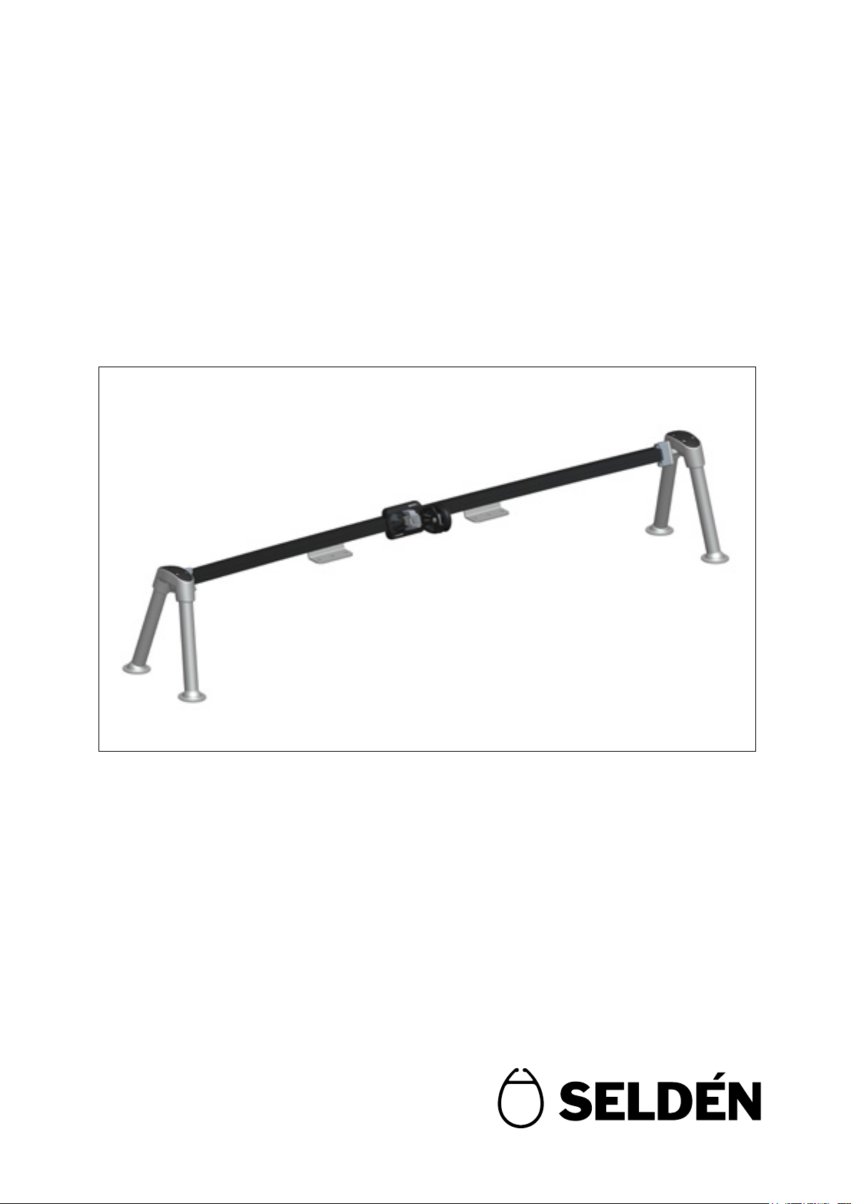
Self-tacking system 22
597-278-E
2018-02-20
For sailboats ranging from 25 to 35 feet

2
Introduction
Congratulations on the purchase of your new self-tacking jib system.
This manual cover assembly and installation for the Seldén self-tacking system 22.
Please read the entire manual before assembly and use of the product, and keep it available
for future references.
Safety precautions
Dimensioning of the system
Self-tacking jib system 22 has a maximum working load of 700 kg.
The key to a properly working and safe installation is correct dimensioning in relation to the boat the
products shall be used for. Seldén provides dimensioning guidelines in catalogues, leaets and on
the website. If there are any questions about selecting the right product, please consult an authorized
Seldén dealer. All dealers are listed at www.seldenmast.com and divided in categories describing their
competence. For Self-tacking jib system 22 we recommend dealers in the category “Advanced Technical
Installations”.
This symbol indicates a delicate moment in the assembly or a technical advice.
This symbol indicates a potential hazardous situation which, in the event of failure,
can lead to damages to property, personal injury or death.

3
Contents page
1. Introduction 2
2. Product information self-tacking system 22 4
2.1 Parts included 6
2.2 Foot options 7
2.3 Track options 7
2.4 Car options 7
2.5 Block options 8
3. Assembly preparations
3.1 Required tools 9
3.2 Required fasteners 9
3.3 Sheet arrangement 10
3.4 Placement of centre console 11
3.5 Track length 12
3.6 Placement of side consoles 12
4. Assembly
4.1 Step by step assembly instructions 13
5. Installation
5.1 Step by step installation instructions 16
6. Service and maintenance
6.1 Frequent service 18
6.2 Annual service 18
7. Options
7.1 Sheet crane 19
7.2 Pad Eyes 19
8. Warranty conditions 20
4
2. Product information
SELF TACKING JIB SYSTEMS
A self-tacking jib makes life on board a lot easier, particularly for short-handed crews. The jib sheet is led
to a car which moves to leeward during the tack with no need to touch the sheet. Tacking is as simple as
steering the boat through the wind.
System 22 is designed as a universal retro-t self-tacking system for sail boats ranging from approximately
25 to 35 feet. The length of the legs can be cut to the correct length and the angle of the track and deck
ttings are adjustable. The track is available from stock in two standard radiuses to give a good alignment
of the sheet load to the car and track. Simply, the system ts to most boats, but exceptions will naturally
occur and should be considered prior the purchase.
Obstacles can be objects such as a hatch or a ventilator tted just forward of the mast or the
construction of the deck which must be solid as opposed to a sandwich construction.
Track, car, consoles, deck ttings and blocks for the sheet arrangement makes for a complete system.
The sail must be designed for a self-tacking system and cannot overlap the mast. The routing of the sheet
must also be planned for in advance. Customized tracks, single curved or double curved can be ordered
by submitting necessary measurements, see enquiry form 595-952-E, available at www.seldenmast.com.
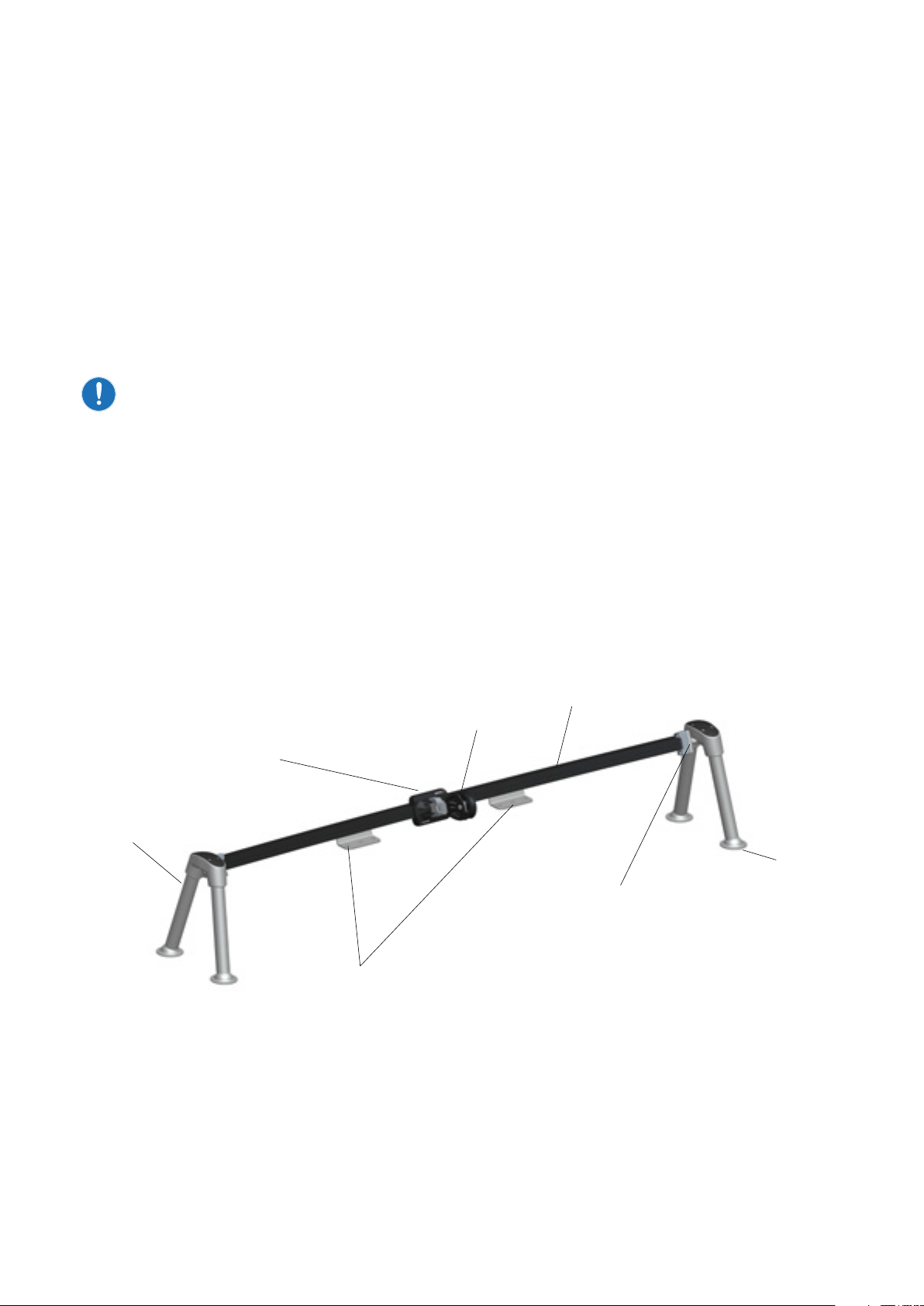
End stops with rubber shock absorbers.
Centre consoles
Car
Side console
Block
Curved track
Foot
5
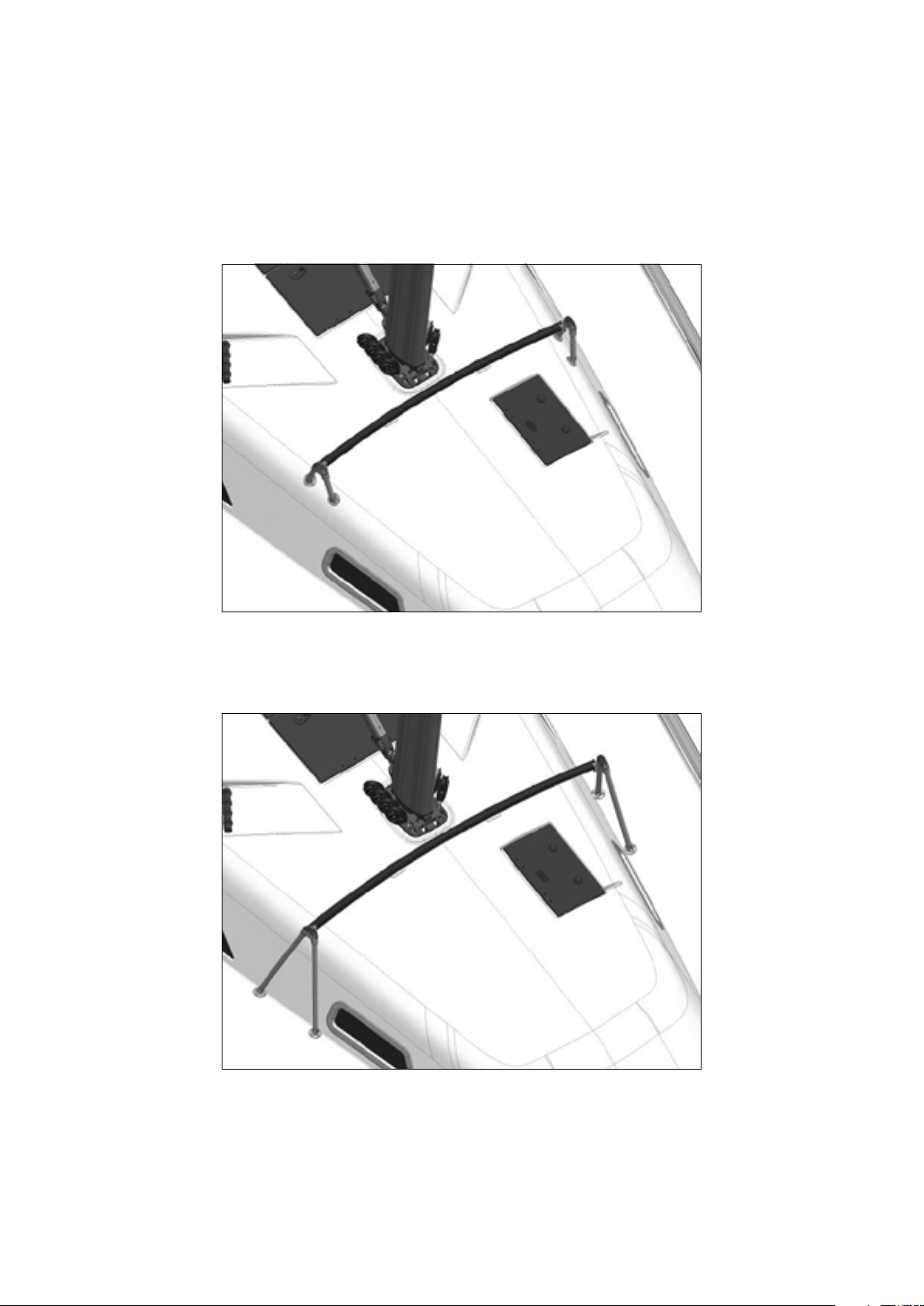
The illustrations below show the two most common ways to install a self-tacking system.
Coach roof mounting
Side deck mounting

6
2.1 Parts included in side console package, art. no. 442-200-10
Side bracket
Item Art. No. Quantity Description
(all measurments in mm)
1 442-200 2 BRACKET 102x52x39
2 442-202 2 WASHER Ø21x7
3 153-006 2 SCREW MC6S M8x20
4 442-203 2 COVER 88x33x13.5
5 153-178 8 SCREW MLC6S M4x8
Joint bracket
1 442-201 2 JOINT BRACKET 79.5x60x40
2 442-205 2 END STOP 42.5x20x17
3 153-178 4 SCREW MLC6S M4x8
4 442-210 4 WASHER PLATE ST-22
5 153-001 4 SCREW MC6S 6x20
- 312-305 2 LOCKING ADHESIVE 1ML
Leg
1 442-204 4 LEG Ø25x500
2 151-120 4 THREAD BAR M8x500
3 164-401 4 WASHER Ø16/8-1.5 (M8)
4 158-006 4 NYLOC NUT M8
- 157-004 8 FULL NUT M8
- 312-305 1 LOCKING ADHESIVE 1ML
Centre console
1 442-209 2 CENTRE CONSOLE 80x51x46
2 151-105 4 SCREW M6x16
3 164-407 4 WASHER Ø12/6-6 (M6)
4 157-003 4 NUT M6M
5 442-211 2 NUT HOLDER
a
b
d
e
ab
d
e
c
c
a
b
dc
ab
d
ec

7
2.2 Foot options (2 alternatives)
Not included in kit 442-200-10, to be ordered separately.
Deck fitting kit, 442-206-10
Enables quick removal of the system when preparing for racing.
Item Art. No. Quantity Description
(mm)
1 443-206 4 DECK FITTING Ø59x27.5
2 442-207 4 END FITTING LEG Ø26x33
3 165-203 4 CLEVIS PIN Ø10x28
4 301-049 4 SPLIT PIN Ø2.9x16
Foot kit, 442-208-10
Item Art. No. Quantity Description (mm)
1 442-208 8 FOOT Ø59x27.5
2 164-403 4 WASHER Ø16/10.5-2.5
3 158-006 4 NYLOC NUT (M8)
2.3 Track options (2 alternatives)
J-measurement
(mm)
Art. No. Description (mm) For sheet arrangement
– 3700 442-011-40 Radius 3000 mm, Length 1700 mm Over the fore deck
(see section3.3)
3700 – 4700 442-011-41 Radius 4000 mm, Length 1800 mm
Custom tracks
For custom tracks, see enquiry form 595-952-E available at www.seldenmast.com.
2.4 Car options (2 alternatives)
Not included in kit 442-200-10, to be ordered separately.
Righting moment at a 30° heel angle
(kNm)
Approximate
displacement
Art. No. Description
<35 <6 442-148-01 Single car
>35 >6 442-148-02 Double car
a
b
d
c
a
b
c

8
Description Art No. Sheet arrangement Safe working Load
(Kg)
PBB60 Single 406-001-01 Over the foredeck 1000
PBB60 Single becket 406-001-02 Up the mast 1000
RBB60 Single 406-201-01 Over the foredeck 1500
RBB60 Single becket 406-201-02 Up the mast 1500
2.5 Block options
Not included in kit 442-200-10, to be ordered separately.
Blocks for 442-148-01, single car
Description Art No. Sheet arrangement Safe Working Load
(kg)
PBB50 Single 405-001-01 Over the foredeck 650
PBB50 Single becket 405-001-02 Up the mast 650
BBB60 Single HD* 406-601-51 Over the foredeck 500
BBB60 Single becket HD* 406-601-52 Up the mast 500
Blocks for 442-148-02, double car
*HD = Heavy Duty

9
3. Assembly preparations
3.1 Required tools
Ensure you have the following tools before starting the assembly:
• Hacksaw
• File
• Allen keys 2.5mm, 5mm and 6mm
• Socket wrench with 13mm socket
• Spanner 10mm
• Measuring tape or ruler
• Pen
• Tape
• Drill, Ø6.2 drill bit
• Marine sealant
3.2 Required fasteners
Fasteners for attaching the self-tacking system to the deck are not included.

10
Up the mast
The advantage of routing the sheet up the mast and back to the cockpit is to keep the foredeck clean
from lines. The sheet is led from the car, up the front of the mast and into the mast through a sheave box
installed at a height of 50% of the fore triangle. The sheet exits the mast through a slot tting and turns
through a block at the foot of the mast and back to the cockpit. The deck light and the steaming light on
the mast might need to be relocated. Sheet cranes are available for boats tted with Vertical Pole Stowage
(VPS) system. See options page 18.
To avoid over loading the sheave box in the mast, a 2:1 purchase on the
sheet and consequently a single becket block for the car is required.
The track to be angled 80° to the horizontal plane.
The load on car and block arrangement is approximate the sheet load x 1.5.
3.3 Sheet arrangement
There are two common ways to set up a sheet arrangement for a self-tacking system.
The sheet can be led over the fore deck or up the mast.
The routing of the sheets aects:
• The angle of the track
• The radius of the track
• The load on the car
Over the fore deck
This is the simplest and most common arrangement. The sheet is led from the clew of the sail,
through a single block on the car, to a block at the bow and back to the cockpit.
The track to be angled 35° to the horizontal plane.
The load on the car and block is approximate sheet load x 1.75.
80º
35º
J
Jt
J
Jt
11
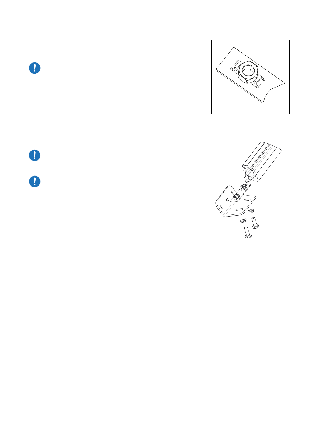
3.4 Placement of centre console
Fit the centre consoles on the track temporary. Use the M6 bolts,
nuts, washers and nut holder included in the kit. Fit the nuts in the nut
holder and slide in to the track as per illustration.
Nut sides need to be “parallel” to track to t.
Assemble the screws, washers and centre console using the slot
shaped holes in the tting. Enter the screws in the nuts but do not
tighten. Slide the centre console to the centre of the track and tighten
the screws.
Mounting the centre console close to the leading edge of the mast/
mast base is preferable as it gives you the option to maximize the jib
foot length and by that the sail area.
The car needs to have clearance to function satisfactory.
The angle of the centre console can be modied by reshaping
the tting.
Single or double centre consoles?
RM (righting moment) at 30° heel angle (Can be calculated at
www.seldenmast.com/online services).
• RM<15 kNm (Jib sheet load approximately 250kg)
Single centre console mounted on centre line.
• RM>15 kNm
Double centre console mounted symmetrically around centre line.
If possible space consoles evenly along track for minimum
unsupported length.
12
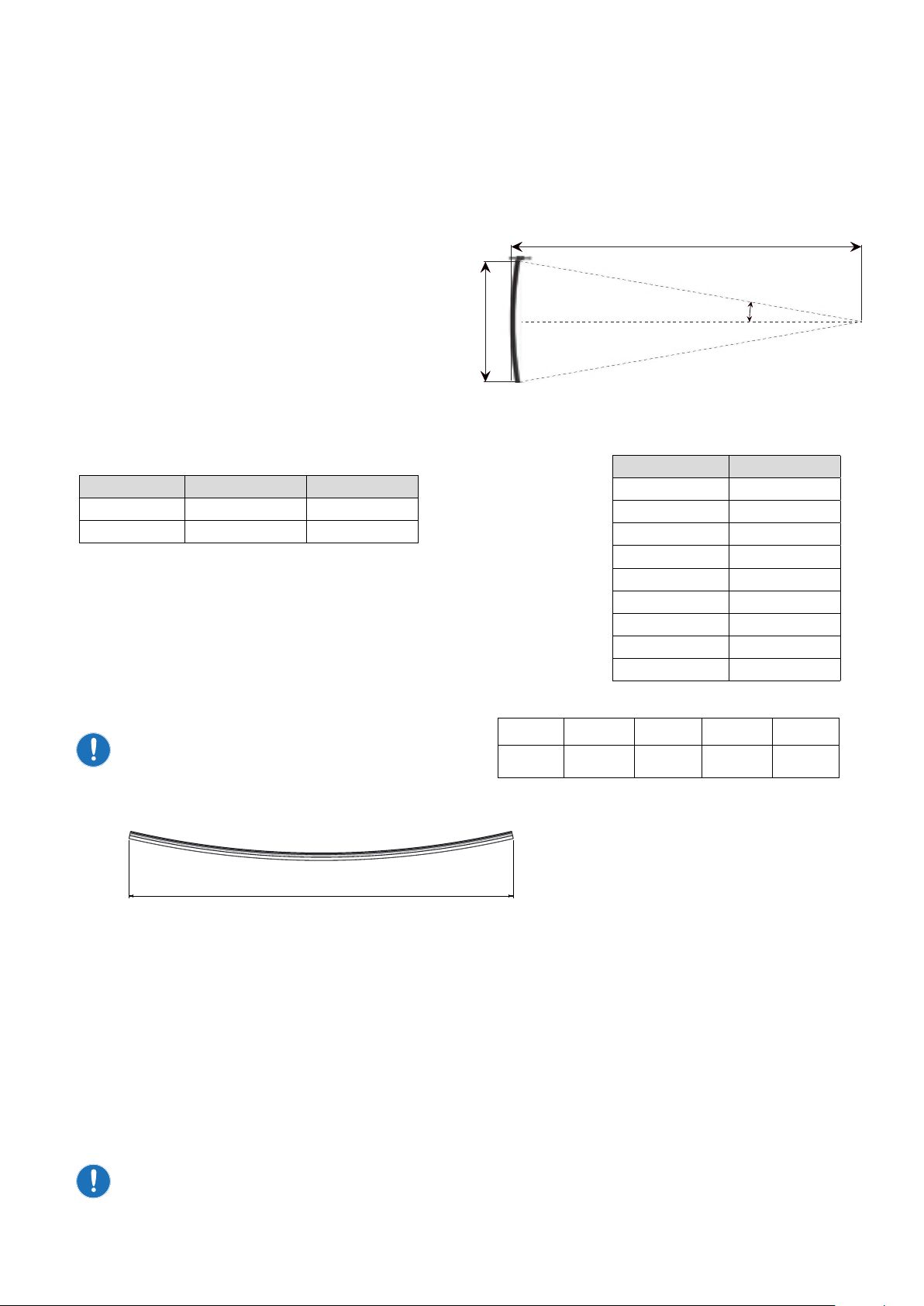
3.5 Track length
The sheeting angle and Jt-measurement will give the length of the track.
Normally an angle of 8-10° works well (an angle under 7° is not recommended).
Consult your sail maker for the recommended sheeting angle for your sail and boat.
• To calculate the length of the track you need the
distance from the forestay to the track (Jt) and
the sheeting angle (a).
• The length of the track for a given angle can be
approximated as follows:
L = 2 x Jt x A + l
A= factor sheet angle, see table, or calculate as:
L=2 x Jt x tan (a) + l
Jt = fore triangle base length, see gure above
l= car length, see table below
• Mark the centre of the track. Measure out (L/2) from the
centre mark to one side of the track, mark this distance
and repeat procedure for the opposite side.
• Measure and check the distance between the end marks,
this distance should be (L).
When measuring distance (L) on a curved
track, make sure you measure in a straight
line between the two end points.
Jt
a
L
Sheet angle (a)A(tan(a))
7.0º 0.123
7.5º 0.132
8.0º 0.141
8.5º 0.150
9.0º 0.158
9.5º 0.167
10.0º 0.176
10.5º 0.185
11.0º 0.194
L
Art. No. Lenght (l) mm Description
442-148-01 85 Single car
442-148-02 175 Double car
3.6 Placement of side consoles and deck fittings
Place the track in the correct position on the foredeck.
Secure the position of the track and centre console on the deck with tape/clamps etc.
Check the track is centred and the end marks on the track corresponds to the chosen sheeting angle.
Position the centre bracket(s) on deck, ensuring no clashes, and mark the position.
With the track in place, check that there is space beneath the end marks on the track to allow the side
consoles and deck ttings to be mounted.
Check that both ends of the track have the same distance from the forestay chain plate.
L = 2 x Jt x A + l
L = 2 x x + =

13
4. Assembly
Before permanently installing the track on deck, we recommend that you do a temporary assembly to make
sure that the deck mounts, track and car do not interfere with any other deck ttings or structures above or
below deck. Parts of the assembly need to occur whilst on the deck of the boat. For actions such as sawing
or grinding, it is recommended this is done away from the boat in a suitable work space.
4.1 Step by step assembly instructions
1.
Cut the track at the measured (see 3.5) end
marks. Ensure the cut is perpendicular to the
radius of the track.
Slide the joint bracket 442-201 into the track.
Make sure that there is no gap between the tting
and the track. Some ling of the track may be
required to achieve a perfect t.
2.
Drill two holes for the joint bracket 442-201 tting
in both ends of the track using a Ø6.2mm drill bit,
see pictures.
Joint bracket 442-201 can be used as a drill
gauge to start the holes.
Remove joint bracket 442-201 when holes are
started.
Drill only through one wall!
Do not drill through the upper surface
of the track!
Do not drill through the rst wall in the
track with 442-201 still assembled, doing
so can damage the threads in 442-201!
3.
Mount the car on the track by rolling it from the
transport track onto the self-tacking track.
Be careful not to drop any ball bearings.
Secure the car on the track with tape, as shown.
2 x Ø6.2
13
31

14
4.
Install joint bracket 442-201 to both sides of the
track with the screws, washers and rubber end
stop. Use locking adhesive on the screws.
It is important that both washers are used
in the assembly, one on the outside and
one on the inside of the prole as shown.
5.
Assemble the bracket 442-200 with a screw and
spherical washer onto the joint bracket 442-201.
Make sure the 442-200 is assembled
on the correct side.
There is an “AFT” marking inside the bracket
442-200.
6.
Insert the M8 threaded bars into the brackets
442-200 and secure with washers and nuts
(none locking)
Place the system on deck according to the
marked position for the centre console and
adjust the threaded bars to approximately the
correct length.
Lock the position and angle of the four bars by
tightening the nuts (none locking).
Make sure there is a free area on the deck at the
end of each bar to install the deck ttings.
Foot kit 442-208-10
Cut threaded bar with over length to ensure
enough threads for deck thickness and
fasteners.
Washers

15
7.
Deck tting 442-206-10
Screw the end tting 442-207 onto the ends of all
four treaded bars.
Assemble the complete deck tting kit as shown.
Place the system on deck with the deck ttings
attached and adjust the threaded bars to
correct length.
Mark the threaded bars 5mm above the nuts and
mark the position on deck or coach roof.
Disassemble the bars and cut to length at the
marked position.
Foot kit 442-208-10
Make an approximate mark of where the treaded
bar will intersect the deck. Use these marks as
reference for foot placement in step 8 when
deciding the length of the legs.
The position and nal length for the threaded bars
will be conrmed during installation.
8.
Measure and calculate the length of the legs
(Ø25mm tubes). Legs to be cut to L+23mm.
The extra 23mm will be hidden inside the
442-200 bracket when assembled.
Forward and aft legs might be dierent in
length. Make sure that the respective legs
on the opposite side are identical in length.
Cut legs with a hacksaw.
9.
Assemble the system and place on deck.
Ensure:
• The track is centred
• Track ends are symmetrical to forestay
• Track is in the correct angle for sheet
arrangement
Adjust side consoles so the deck ttings and
centre consoles are on the marked positions
on deck.
Check there is accessibility below deck to t nut
and washer.
LL
Deck tting
Foot kit

16
5. Installation
To simplify the nal installation, disassemble the centre console and side bracket from the track.
Leave both joint brackets (442-201) assembled on the track.
5.1 Step by step installation instructions
1.
Install the centre bracket to the deck at the
marked position. Use 3xM6 screws (not supplied)
and marine sealant.
Assemble the track to the centre console, make
sure the centre mark is on the boats centerline.
Tighten the two screws on the centre bracket.
2.
Deck tting 442-206-10
If deck tting 443-206 is used, add locking
adhesive to the threads in end tting (442-207)
and screw onto the threaded bars.
Fit the legs, nuts (locking) and washers to the
brackets 442-200 and tighten rmly.
Foot kit 442-208-10
If deck tting 442-208 is used, assemble the legs,
nuts (locking) and washers to the bracket 442-200.
System to be tightened from below deck when
placed in position.
3.
Attach the side consoles to the track.
Leave the screw engaged but loose to allow for
adjustment.
Spherical washer can be adjusted for correct
angle of the side console.
Deck tting Foot kit
17
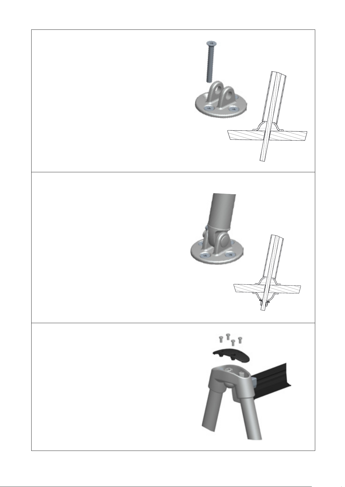
4.
Deck tting 443-206-10
Install the deck ttings at the marked positions on
deck. Make sure the deck tting 443-206 is at the
correct angle to t the side console when assembled
to the track. Use 4xM6 countersunk screws for each
tting. Apply marine sealant.
Foot kit 442-208-10
With the system in correct position and the side
consoles at desired angle, aim with the legs on deck
and mark the position.
Drill holes through deck at your markings. Pay extra
attention to the angle of the threaded bar, align hole
after this angle, see illustration.
5.
Place system in position on deck.
The screws in the joint brackets and the nuts
on the legs might need to be eased to adjust
components into place.
Deck tting 443-206-10
Assemble deck ttings with clevis pin and split
pin and tighten all screws on the system
Foot kit 442-208-10
Place deck tting 442-208 under every leg on deck.
Apply marine sealant.
From inside the boat place the foot 442-208, washer
and nut on all threaded bars and screw tight.
Saw o redundant thread bar.
Tighten all screws in the system.
6.
Fit the covers with four screws.
Installation completed!
Deck tting
Foot kit
Deck tting
Foot kit

18
6. Service and maintenance
6.1 Frequent maintenance
Cleaning
Rinse the self-tacking system with fresh water regularly to get rid of salt and dirt.
A mild detergent can be used to help get dirt o.
Pay extra attention to the ball bearings inside the car. Rinse the car thoroughly with fresh water
while moving it back and forth on the track.
Make sure the track is clean and free from damage that might cause the car to malfunction.
Pay extra attention to the ball race where the ball bearings run. Wipe with cloth to ensure the
surface is clean.
Lubrication
Seldén high performance Lubricant can be used to lubricate the car.
Art. No. 312-534
6.2 Annual maintenance
Check that all screws are tight.
• Open the lid on the side console and check so the nuts are tight
• Check the hex screw for the joint bracket
• Check the two screws on the back of the centre bracket
The self-tacking system and yacht are at risk of damage if fasteners are not completely
tightened during assembly. Improper tightening of fasteners can result in assembly failure
and potential for personal injury.

19
FOLDABLE PAD EYES
Stainless AISI 316
Art. No. Dimension
(mm)
Weight
(g)
Safe
working load (kg)
Breaking
load
(kg)
Bolts
508-750-01R Ø6/42x42 74 1100 2200 3xM6
508-760-01R Ø8/54x54 154 2200 4400 3xM8
7. Options
7.1 Sheet crane and exit box
For boats tted with vertical pole storage (VPS) and for boats where a
“up the mast” routing of the sheet would need a relocation of the deck
and steaming light. The sheet crane creates the separation you need
between the mast and sheet to facilitate VPS, navigation and deck lights.
7.2 Foldable Pad eyes
Used for mounting a turning block at the bow.
H
L
Mast section Max RM at
30°, kNm
Sheet crane
Art.No.
Length, mm (L)
Sheet exit box,
Art. No.
Min distance
between sheet
box and crane,
mm (H)
Max line size,
ø mm
C227-C304
F228-F305 170 508-094-01
L=200 505-016-01 1200 12
C264-C365
F265-F370
508-093-01
L=275 505-015-01 1500 14
SHEET CRANE AND EXIT BOX

20
8. Warranty
Seldén Mast AB guarantees Self-tacking jib system 22 for 2 years. The guarantee covers faults arising from
defective design, materials or workmanship.
The guarantee is only valid if the product is assembled, operated and maintained in accordance with this
manual and is not subjected to loads in excess of those indicated in the brochure and on the Seldén website.
Complete shipment and warranty conditions are to be found on Seldéns website www.seldenmast.com.
See Resources/Partners information/General information/General conditions of sale (595-546-E).
If the system is repaired or modied by anyone other than Seldén Mast AB or one of our authorized dealers,
the guarantee ceases to be valid.
Seldén Mast AB reserves the right to alter the content and design without prior warning.
Table of contents
Other Selden Boating Equipment manuals

Selden
Selden Single Line Reef User manual

Selden
Selden RB User manual

Selden
Selden Furlex 404E Instructions and recipes

Selden
Selden 507-309-01 User manual

Selden
Selden 597-081-EF Owner's manual

Selden
Selden Furlex 50 S User manual

Selden
Selden CXe25 OD User manual

Selden
Selden Rodkicker 05 User manual

Selden
Selden SMF RC Guide

Selden
Selden Furlex 500 H Series Instructions and recipes

Popular Boating Equipment manuals by other brands


Humphree
Humphree HCS-5 installation manual

Vetus
Vetus BOW4512D Operation manual and installation instructions

Dock Doctors
Dock Doctors SLIDING BOARDING STEP Assembly instructions

Mastervolt
Mastervolt Mass Combi 12/2000-100 Quick installation

SeaView
SeaView PM5-FMD-8 installation instructions

Hobie
Hobie Mirage 360 manual


