Selden Furlex 404E Instructions and recipes

597-464-E
2020-05-26
Supplementary manual Furlex 404E

2
1. Introduction
Congratulations on the purchase of your new Furlex Electric motor unit. This manual covers installation
and operating instructions for the electric drive unit only.
Installation of the basic furling systems are described in their respective manuals (see below). The model
designation is found on the cover. Part and serial numbers are found on the gearbox, inside the respective
covers.
The Furlex Electric motor unit is compatible with the following manually operated Furlex models:
404S/404TD (current models)
400S/400TD (discontinued models)
The electric furling unit is only to be used together with Seldén’s power supply and SEL-Bus system.
We have compiled this manual to help you install and operate your furling system safely and with ease.
Please read the entire manual before assembly and use of the product. Follow the instructions carefully
to avoid damage to the furling system and to avoid the risk of personal injury. Seldén cannot be held
responsible for any problems, damages or personal injuries arising from an improperly installed product.
Keep the manual available for future reference.
User Manual Revision history:
597-464 Revision 0.0 2020-03-13
The latest version of this manual can be downloaded from www.seldenmast.com
Other Seldén documents referred to in this manual are:
595-116 Furlex 400S
597-181 Furlex 404S
595-240 Furlex 400TD
597-465 Furlex 404TD
597-275 Power supply & SEL-Bus system
An electric converted 400S will have designation 400E MkII
and a 400TD will have designation 400TDE MkII .
Safety Precautions
Carefully pay attention to, and follow the instructions with the following symbols:
ATTENTION
This symbol indicates a critical moment in the assembly or technical advice.
WARNING
This symbol indicates a potentially hazardous situation. If not avoided, this could result
in serious personal injury or damage to property.

Safety notes regarding the electrical installation for the Furlex Electric:
-The installation should be done by a person with marine installations skills. You can nd your local
authorized Furlex dealer at www.seldenmast.com
-Furlex electric is intended only for sail furling purposes together with Seldén furling proles, controlled
by Seldén’s 42V motor drive system.
-Make sure the system is switched o before performing any installation or service.
-Never modify the electric system of your Furlex or its installation drawings - installation, alterations and
maintenance should be performed by a competent marine electrical technician.
-Never alter or modify the rated current amperage of overcurrent protective devices.
-Never leave the craft unattended with the Furlex Electric energized.
Choosing the correct version of Furlex Electric for your boat:
The key to a safe and properly working installation is correct dimensioning in relation to the boat size the
products shall be used on. Seldén provides dimensioning guidelines in catalogues, leaets and on the web-
site. If there are any questions about selecting the right product, please consult an authorized Seldén dealer.
All dealers are listed at www.seldenmast.com and divided in categories describing their competence. For
Furlex Electric we recommend dealers in the category “Advanced Technical Installations”.
3

Contents
1 Introduction ......................................................................................................................... 2
Contents ................................................................................................................................... 4
2 Furlex Electric................................ ..................................................................................... 5
2.1 Basic Packs for Furlex Electric complete kit ........................................................... 6
2.2 Furlex Electric Retrot pack..... ................................................................................. 8
2.3 Control Pack .............................................................................................................. 10
2.4 Optional parts ............................................................................................................ 11
2.5 Technical specication ............................................................................................. 12
3 Motor Unit installation ........................................................................................................ 14
3.1 Installation preparations Furlex Electric (above deck) .......................................... 14
3.2 Installation preparation for Furlex TD Electric (Through deck) ............................ 15
3.3 Installation of the furling system excluding the electric motor unit .................... 15
3.4 Step by step assembly 404E ................................................................................... 16
3.5 Step by step assembly 404TDE .............................................................................. 18
3.6 Step by step assembly 400S Retrot .................................................................... 21
3.7 Step by step assembly 400TD Retrot .................................................................. 23
3.8 Step by step assembly 404S Retrot ..................................................................... 27
3.9 Step by step assembly 404TD Retrot ................................................................... 32
4 Electrical Installation .......................................................................................................... 38
4.1 Installation of deck gland and connection box. .................................................... 38
4.2 Connection to Seldén Power supply and SEL-Bus system ................................. 41
5 Operation ............................................................................................................................. 42
5.1 Normal operation ...................................................................................................... 42
5.2 Unfurling ..................................................................................................................... 42
5.3 Furling ......................................................................................................................... 42
5.4 Reducing sail area .................................................................................................... 43
5.5 Emergency furling ..................................................................................................... 44
6 Trouble shooting ................................................................................................................. 45
7 Service and maintenance .................................................................................................. 46
7.1 Frequent maintenance .............................................................................................. 46
7.2 Yearly Inspection points and maintenance............................................................. 46
7.3 Every 5th year ............................................................................................................ 46
8 Technical information ......................................................................................................... 48
4
5
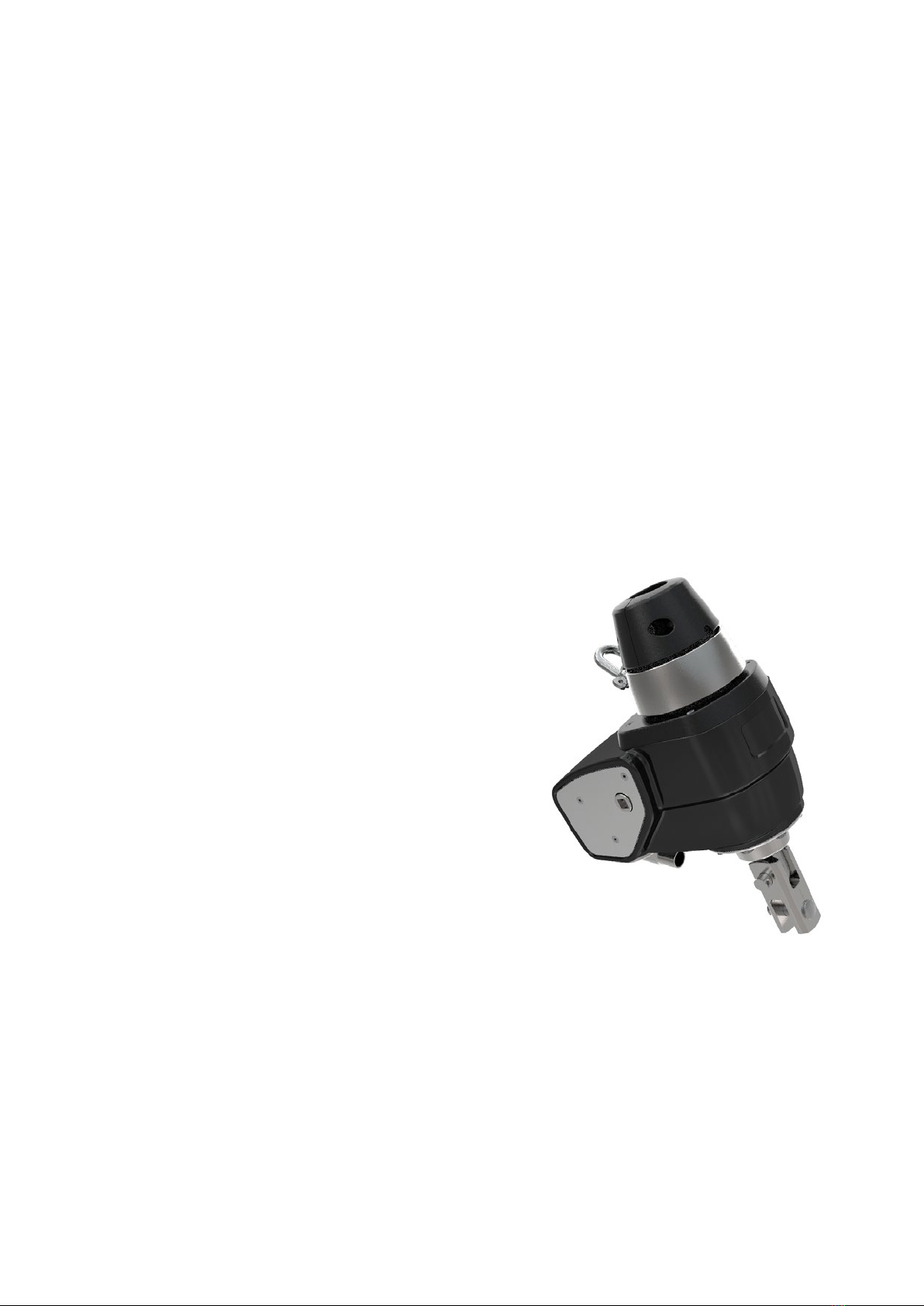
2 Furlex Electric
Furlex Electric is available as a complete kit for both on-deck and through-deck installation.
The electric system is also available as an upgrade of an existing Furlex by replacing the furling line,
drum and line guard assembly with the Furlex Electric Motor unit and related parts in the Furlex
Electric Retrot pack.
Low power consumption
High eciency throughout the electric power and control system. A “sleep mode” is activated to
save power when not in operation.
Powerful enough, but with precise torque limitation.
The electric motor has a computerised controller that monitors the current draw precisely. As soon
as it reaches a pre-set level it cuts out quickly enough to avoid damage to components. The torque
level is programmed into a memory chip so that each size of Furlex Electric has the correct setting.
Resistant to the marine environment
The gear house is machined from high grade corrosion resistant aluminium and andodized.
All stainless parts in 316 or 316L. The electric motor has its own housing which is completely sealed
and individually pressure tested before delivery.
Two speed operation
A double control button makes it possible to operate the
furler with great precision in the low speed mode.
By pushing both buttons at the same time, high
speed is activated.
Locks in both directions
The worm gear is self-locking (40:1) in both directions,
which means that the sail can be furled from either
the starboard, or the port side of the boat.
Emergency operation
The worm gear has a ½” socket that can be reached
from the starboard side. Seldén’s emergency line
driver is included in the delivery kit.
Compact size -minimised weight and dimensions.
The electric motor is compact, still giving enough power.
This is made possible by raising the voltage up to 42V.
Keeping weight and the dimensions in focus during the
design has resulted in a small unit.
Table of contents
Other Selden Boating Equipment manuals

Selden
Selden 507-309-01 User manual

Selden
Selden CXe25 OD User manual

Selden
Selden 22 User manual

Selden
Selden Single Line Reef User manual

Selden
Selden Furlex 50 S User manual

Selden
Selden Furlex 500 H Series Instructions and recipes

Selden
Selden SMF RC Guide

Selden
Selden Rodkicker 05 User manual

Selden
Selden RB User manual

Selden
Selden Furlex 300 H Quick start guide

Popular Boating Equipment manuals by other brands


Humphree
Humphree HCS-5 installation manual

Vetus
Vetus BOW4512D Operation manual and installation instructions

Dock Doctors
Dock Doctors SLIDING BOARDING STEP Assembly instructions

Mastervolt
Mastervolt Mass Combi 12/2000-100 Quick installation

SeaView
SeaView PM5-FMD-8 installation instructions

Hobie
Hobie Mirage 360 manual


