Selden Furlex 500 H Series Instructions and recipes

Supplementary Manual
Furlex
500 H
595-095-E
2008-09-23
500 H
These pages replace
corresponding pages of
manual 595-119.

One 1000 mm (39 3/8”)luff extrusion with
long joining sleeve
+ bearing plug with bushes
One 2000 mm (78 3/4”) luff extrusion with dis-
tance tube halves.
4800 mm (189”) luff extrusions with distance
tube halves + joining sleeve (number dependent
on length ordered.)
One connecting plate for 1000 mm
(39 3/8”) extrusion.
One connecting plate for each
4800 mm (189”) extrusion.
Forestay wire
Luff extrusion tube
Tools needed for assembly:
Screwdriver•
Hacksaw•
2 adjustable spanners (one of smaller type,•
or No 16 fixed open ended)
Channel-joint Pliers•
Adhesive tape•
File•
Marking pen, waterproof•
8 mm Allen Key (supplied with kit)•
Steel measuring tape (20 m) (60’7”)•
Knife•
Tools
Forestay wire & bushing, 1 off
For halyard leads:
Heavy-duty Philips screwdriver•
Drill•
Drill bit Ø• 5.3 mm (7/32”)
(included in package)
6

Determine mast rake with fore and backstays tensioned.1.
Slacken off the backstay as much as possible. Use the genoa halyard to pull the masthead forward. Tie the2.
halyard to the boat, do not use the snap-shackle. Remove the forestay without altering the setting of the
rigging screw if fitted. Place the forestay on a smooth surface and measure its length (FL) with the steel
measuring tape.
Note the forestay length (FL) in the following table. The correct wire length (WL) can then be calculated.3.
Measure the new wire from the centre of the hole in its end fitting. Mark off the length WL on the wire in4.
such a way that it cannot be eradicated. Do NOT cut the wire yet.
Note! Use caution when opening the roll of wire.
FORESTAY WIRE LENGTH (See fig. 8.1) Your stay Example
FL Old forestay length (FL) without tension, but including rigging screw (if any).
(See fig 8.1)
TDeduction for lowerwire terminal: - -
If a link or an extra toggle will be fitted then deduct its length from FL.
Note: Any additional link or toggle must have a torsional strength (tor-
que capacity) not less than the stem-head fitting requirement stated on
page 9, second item.
- -
WL Cut the new forestay wire at this length (WL, fig. 8.2) = =
LUFF EXTRUSION LENGTH (See fig. 8.2) Your foil Example
WL New forestay wire length as per table above
A + B Standard deduction (A + B): - -
C + D C + D = = =
CMax. number of 4800 mm extrusions which together are shorter than
C + D: . . . . . . . . . off x 4800 mm D = - -
DCut the top extrusion. Chamfer the cut end with a file.
Length of top extrusion D =
If D is longer than 2000 mm;
cut the top section from a 4800 mm extrusion.
If D is between 1000 and 2000 mm;
cut the top section from a 2000 mm extrusion.
If D is shorter than 1000 mm;
replace the topmost 4800 mm extrusion with a 2000 mm extrusion. (See C).
The join will then be moved down 2800 mm. Also adjust C and D as follows:
Reduce measurement C by 2800 mm. Increase the D measurement by 2800
mm. Cut the top section from a 4800 mm extrusion.
= =
ECut the distance tube for the top extrusion: (fixed measurement) - -
Distance tube length E = = =
Calculations for wire ø16 –
500 H
500
1.320
500
28.000
500
27.500
27.500
1.320
26.180
24.000
2.180
500
1.680
(5 extrusions)
7a

150
FORESTAY ROD LENGTH (See fig. 8.1) Your stay Example
FL Old forestay length (FL) without tension, but including rigging screw (if any).
(See fig 8.1)
T
Deduction for lower rod terminal (rigging screw 50% extended):
ROD 40: – 495 mm
ROD 48: – 500 mm
ROD 60: – 505 mm
- -
If a link or an extra toggle will be fitted then deduct its length from FL.
Note: Any additional link or toggle must have a torsional strength (tor-
que capacity) not less than the stem-head fitting requirement stated on
page 9, second item.
- -
WL Cut the new forestay rod at this length (WL, fig. 8.2) = =
LUFF EXTRUSION LENGTH (See fig. 8.2) Your foil Example
WL New forestay rod length as per table above
A + B
Standard deduction (A + B):
ROD 40: – 1380 mm
ROD 48: – 1400 mm
ROD 60: – 1420 mm
- -
C + D C + D = = =
CMax. number of 4800 mm extrusions which together are shorter than
C + D: . . . . . . . . . off x 4800 mm C = - -
DCut the top extrusion. Chamfer the cut end with a file.
Length of top extrusion D =
If D is longer than 2000 mm;
cut the top section from a 4800 mm extrusion.
If D is between 1000 and 2000 mm;
cut the top section from a 2000 mm extrusion.
If D is shorter than 1000 mm;
replace the topmost 4800 mm extrusion with a 2000 mm extrusion. (See C).
The join will then be moved down 2800 mm. Also adjust D and E as follows:
Reduce measurement C by 2800 mm. Increase the D measurement by 2800
mm. Cut the top section from a 4800 mm extrusion.
= =
ECut the distance tube for the top extrusion: (fixed measurement) - -
Distance tube length E = = =
Determine mast rake with fore and backstays tensioned.1.
Slacken off the backstay as much as possible. Use the genoa halyard to pull the masthead forward. Tie the2.
halyard to the boat, do not use the snap-shackle. Remove the forestay without altering the setting of the
rigging screw if fitted. Place the forestay on a smooth surface and measure its length (FL) with the steel
measuring tape.
Note the forestay length (FL) in the following table. The correct rod length (WL) can then be calculated.3.
Calculations for rod stay –
500 H
28.000
500
27.500
27.500
1.400
26.100
24.000
2.100
150
1.950
(5 extrusions)
7b

8
Fig. 8.1 Fig. 8.2
FL = Old forestay length
A
E
CB
D
WL= Wire length or Rod length
T

1. The forestay is fitted with a stout torsion-resistant lower toggle (see fig. 9.2). This is attached to the stem-
head fitting. The toggle can be fitted either athwartships or fore-and-aft.
2. Check that the stem-head fitting and the toggle are suited (see table below). The stem-head fitting must
be able to withstand a torque of 1200 Nm for Wire Ø 16, Rod 40 and Rod 48, or 1600 Nm for Rod 60
(Maximum working load).
3. Check that the drive unit goes free of the pulpit, bow anchor, or other deck equipment. (See fig. 9.1 and the
table).
G 1/2”
B=
A=
Max width 184 mm
FL
HV
D
3
D
2
3/8” Hydraulic hoses, 2 off
Quick couplings, 2 off
L
G
D1
All measurements in millimeters
Installation
Forestay installation to deck
4. Protect the hydraulic hoses an through-deck fitting from the anchor chain.
5. Siting of the through-deck fitting is to your choice. Send measurements A and B to Seldén Mast AB or your
dealer. We will then make up the two hydraulic hoses for the motor. See fig. 11.1 for the through-deck fit-
ting dimensions. A Ø 72 mm hole through the deck is required.
500 H
Ø D1G L Ø D2Ø D3H V
Wire Ø 16 25.4 26 45 90 160 430 140
ROD 40 25.4 26 45 90 160 430 140
ROD 48 28.6 29 50 90 160 430 140
ROD 60 31.8 32 55 90 160 430 140
Fig. 9.2
Fig. 9.1
9
Through-deck fitting

The drive unit and hydraulic motor are tested before delivery.
The hydraulic motor is a Danfoss OMM 20 cm3/revolution. Maximum recommended pressure, p=140 bar.
The oil flow, Q=20 litres/min. gives a nominal speed n=40 rpm.
The normal working load when reefing or unfurling is p=40 bar when Q is 19 litres/min.
A 24-volt hydraulic pump unit with an effect of P=3 kW is usually sufficient.
Through-Deck fitting
The main installation dimensions are shown in fig. 11.1.
Quick couplings
The quick couplings (fig. 11.2) are disconnected by pushing the knurled coupling sleeves out from
the coupling. The coupling sleeves have safety locks to guard against involuntary disconnection.
These are freed by twisting the locking rings until they release.
Always check that quick couplings are locked!
By-pass valve in working position
Ø 110 mm
Ø 72 mm
Coupling sleeve
Safety lock
Female
Quick coupling
Male
Fig. 11.2
Fig. 11.1
G 1/2”
45 mm
Installation
Hydraulic motor
11
By-pass valve in position for manual operation

Hydraulic hoses
Hydraulic hoses for installation below deck are1. not supplied. (See fig. 12.1).
Connecting threads are G 1/2”. (See fig. 11.1).2.
Use hydraulic hoses of good quality corresponding so SAE 100R7/-ISO3949.3.
Minimum dimension 1/2”. Minimum working pressure 140 bar. Minimum recommended bending radius
150 mm (6”).
Put suitable marks on the hoses where they connect to the quick coupling. If they are crossed over the opera-
tion of the hydraulic motor will be reversed.
Relay box
Fig. 12 .1
Hydraulic motor Switch panel
Through-Deck fitting
Typical below decks installation.
Not supplied.
Hydraulic
Pump unit
Battery
Important! Blow through all new hoses with compressed air to clean them from possible dust
and dirt before fitting. Check the system very thoroughly during assembly to ensure that no
impurities are present.
When disconnecting the quick coupling, always apply the protective covers and sleeves
supplied.
12

F
Max sail space
FL -(F+E)
FL
1100 mm
CB
E
The sail
The sail should be made for rolling up on the starboard side of the
luff foil.
Any sun-strip should therefore be on the starboard side of the sail.
A high cut clew can give a constant sheet angle even when reefing.
The luff tape ”hard line” should end above the sail feed. (See fig.
31.1).
We recommend webbing on both the head and tack.
Wire head pendant
Sail with a luff more than
500 mm (19”) shorter than
the maximum luff length
should be fitted with a
permanent wire head pendant.
The pendant and sail luff
together should not have a
total length exceeding the
maximum permissible luff length.
Fig. 31.2
Furlex
Hydraulic
500 H
Extrusion
Dimension
A
mm
B
mm
Max
Luff tape
mm
Cut-back
CB mm
F
mm
E
mm
F+E
MM
Wire Ø 16 60/46 3.0 Ø 9 Ø 7 100 620 675 1295
ROD 40 60/46 3.0 Ø 9 Ø 7 100 620 675 1295
ROD 48 60/46 3.0 Ø 9 Ø 7 100 620 675 1295
ROD 60 60/46 3.0 Ø 9 Ø 7 100 620 675 1295
Luff extrusion
The sail luff should slide very easily in the groove as friction
increases very greatly over the whole luff length.
Fig. 31.3
A
B
Fig. 31.1
31

Notes/Comments

Notes/Comments

Important points to remember before sailing
The sail rolls on to the starboard side of the luff extrusion.
The halyard angles out 5–10° from the forestay with sail set.
All sails used have the right total luff length. See page 31.
No lines or halyards can get caught in either the swivel or sail.
The tack ring is in the right position. See page 20.
The winch handle is not in the drive unit when that is out of use. It will rotate very fast if the sail
is rolled in or out.
The by-pass valve is correctly set when operating manually.
The quick couplings are properly locked. Look at page 11.
595-095-E Printed in Sweden. Seldén and Furlex are registered trademarks of Seldén Mast AB
Seldén Mast AB, Sweden
Tel +46 (0)31 69 69 00
Fax +46 (0)31 29 71 37
Seldén Mast Limited, UK
Tel +44 (0) 1329 504000
Fax +44 (0) 1329 504049
e-mail [email protected]
Seldén Mast Inc., USA
Tel +1 843-760-6278
Fax +1 843-760-1220
e-mail [email protected]
Seldén Mast A/S, DK
Tel +45 39 18 44 00
Fax +45 39 27 17 00
Seldén Mid Europe B.V., NL
Tel +31 (0) 111-698 120
Fax +31 (0) 111-698 130
e-mail [email protected]
Seldén Mast SAS, FR
Tel +33 (0) 251 362 110
Fax +33 (0) 251 362 185
e-mail [email protected]
www.seldenmast.com
Dealer:
DINGHIESKEELBOATSYACHTS
The Seldén Group is the world’s leading manu-
facturer of masts and rigging systems in carbon
and aluminium for dinghies, keelboats and yachts.
The Group consists of Seldén Mast AB in Sweden,
Seldén Mast A/S in Denmark, Seldén Mast Ltd in
the UK, Seldén Mid Europe B.V. in the Netherlands,
Seldén Mast Inc in the USA and Seldén Mast SAS
in France. Our well known brands are Seldén and
Furlex. The worldwide success of Furlex has ena-
bled us to build a network of over 750 authorised
dealers covering the world’s marine markets. So
wherever you sail, you can be sure of fast access to
our service, spare parts and know-how.
Table of contents
Other Selden Boating Equipment manuals
Selden
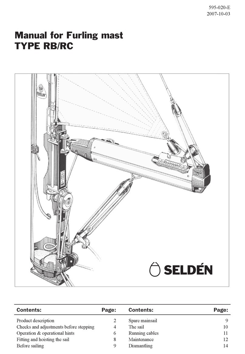
Selden RB User manual
Selden
Selden SMF RC Guide
Selden
Selden Single Line Reef User manual
Selden
Selden Rodkicker 05 User manual
Selden
Selden 507-309-01 User manual
Selden
Selden 22 User manual
Selden
Selden CXe25 OD User manual
Selden
Selden Furlex 404E Instructions and recipes

Selden
Selden Furlex 300 H Quick start guide
Selden
Selden Furlex 50 S User manual
Popular Boating Equipment manuals by other brands

Humphree
Humphree HCS-5 installation manual

Vetus
Vetus BOW4512D Operation manual and installation instructions

Dock Doctors
Dock Doctors SLIDING BOARDING STEP Assembly instructions

Mastervolt
Mastervolt Mass Combi 12/2000-100 Quick installation

SeaView
SeaView PM5-FMD-8 installation instructions

Hobie
Hobie Mirage 360 manual


