Selden CXe25 OD User manual

Manual for assembly and operation
TD & OD
597-963-E
2023-02-27
CXe
25
&
CXe 45

2
Introduction
Congratulations on the purchase of your new Seldén CXe electric Code 0 furler.
This manual covers installation and operating instructions for CXe 25/45 TD (through deck) and
CXe 25/45 OD (on deck).
Please read the entire manual before assembly/usage and keep the manual available for future reference.
The latest version is available at www.seldenmast.com.
Related installation manuals and user guides:
Power supply and SEL-Bus system: Manual 597-275-E
Safety precautions
Choosing the correct version of furler for your boat:
The key to a safe and properly working installation is correct dimensioning in relation to the boat size the
products shall be used on. Seldén provides dimensioning guidelines in catalogues, leaets and on the
website. If there are any questions about selecting the right product, please consult an authorized Seldén
dealer. All dealers are listed at www.seldenmast.com.
Safety notes regarding the electrical installation for the CXe:
-The installation should be done by a person with marine installations skills. You can nd your local
authorized Seldén dealer at www.seldenmast.com.
-CXe is controlled only by Seldén’s 42V motor drive system.
-Make sure the system is switched o before performing any installation or service.
-Never modify the electric system of your CXe or its installation drawings - installation, alterations
and maintenance should be performed by a competent marine electrician.
-Never alter or modify the rated current amperage of overcurrent protective devices.
-Never leave the craft unattended with the CXe energized.
This symbol indicates a delicate moment in the assembly or a technical advice.
This symbol indicates a potential hazardous situation which, in the event of failure,
can lead to damages to property, personal injury or death.

3
Contents page
1 Introduction ..................................................................................................................... 2
2 Presentation .................................................................................................................... 4
2.1 Basic Packs for CXe complete kit ........................................................................ 4
2.2 Control pack............................................................................................................. 5
2.3 Optional parts .......................................................................................................... 6
2.4 Technical specication ........................................................................................... 7
3 Drive unit installation CXe TD through deck .............................................................. 8
3.1 Assembly preparations ...........................................................................................8
3.2 Deck cut-out............................................................................................................. 9
4 Installation ...................................................................................................................... 12
4.1 Fitting the deck collar ........................................................................................... 12
4.2 Fitting the drive unit .............................................................................................. 12
4.3 Assembly of the collar ........................................................................................ 14
4.4 Assembly of the drive unit .................................................................................... 15
5 Drive unit installation CXe TD through bow sprit ..................................................... 16
5.1 Assembly preparations......................................................................................... 16
5.2 Deck cut-out .......................................................................................................... 17
6 Installation ..................................................................................................................... 18
6.1 Fitting the deck collar ........................................................................................... 18
6.2 Fitting the drive unit .............................................................................................. 18
6.3 Assembly of the deck collar ................................................................................ 19
6.4 Assembly of the drive unit .................................................................................. 20
7 Electrical installation .................................................................................................... 22
7.1 Assembly of the deck contact housing and power cable ............................... 22
7.2 Assembly of connector ....................................................................................... 23
7.3 Connection to Seldén Power supply and SEL-Bus system ........................... 24
8 Operation ..................................................................................................................... 25
8.1 Normal operation ................................................................................................... 25
8.2 Unfurling .................................................................................................................. 25
8.3 Furling ..................................................................................................................... 26
8.4 Securing the system ............................................................................................. 26
8.5 Emergency furling ................................................................................................. 26
9 Trouble shooting .......................................................................................................... 27
10 Service and Maintenance ........................................................................................... 28
10.1 Frequent maintenance.......................................................................................... 28
10.2 Yearly Inspection points and maintenance ....................................................... 28
11 Technical Information .................................................................................................. 29
12 Disposal ........................................................................................................................ 29
13 Warranty ....................................................................................................................... 29

4
2. CXe
CXe is a two-speed electric furler for Code sails and with a Selden tack adaptor also for top-down furling
gennakers. CXe is available as an on-deck (designated OD) and through deck installation (designated TD).
Low power consumption
High eciency throughout the electric power and control system. A “sleep mode” is activated to save power
when not in operation.
Powerful enough, but with precise torque limitation.
The electric motor has a computerised controller that monitors the current draw precisely. As soon as it
reaches a pre-set level it cuts out quickly enough to avoid damage to components. The torque level is
programmed into a memory chip.
Resistant to the marine environment
CXe uses anodized 6000-series aluminium components. Plastic components are PC and PA, glass bre
reinforced and UV stabilized. The motor and reduction gear operates in the oil lled and sealed aluminium
housing. The drive units are individually pressure tested before delivery.
A double seal between deck collar and drive unit prevents water intrusion (TD)
Two speed operation
A double control button makes it possible to operate the furler with great precision in the low speed mode.
By pushing both buttons at the same time, high speed is activated.
Limited brake
The reduction gear and motor gives a limited brake function but will not protect against involuntary unfurling.
See chapter 8 for more information.
Compact size. Minimized weight and dimensions.
The electric motor is compact, still giving enough power. This is made possible by raising the voltage up to
42V. Keeping weight and the dimensions in focus during the design has resulted in a small unit.
2.1 Basic Packs for CXe45 complete kit
CXe25 OD CXe25 TD CXe45 OD CXe45 TD
Parts included Qty 545-455-18 545-455-28 545-455-20 545-455-30
Drive unit 1 545-455-09 545-455-10 545-455-11 545-455-12
Deck collar assembly 1 - 545-465-01 - 545-465-01
Insulators 2 - 530-778 - 530-778
Screws M8x40 4 - 153-008 - 153-008
Bag 1 596-196 - 596-196 -
Deck connector kit 1 532-830-01 - 532-830-01 -
Deck connector
housing with support
1 532-833-01 - 532-833-01 -
Manual 1 597-963-E 597-963-E 597-963-E 597-963-E

5
2.2 Control pack
CXe is used together with the Seldén Power supply and SEL-Bus system. The drive unit is connected to a
motor control unit (MCU), which enables communication with the power supply unit and the OUT/IN push
buttons. The CXe is either connected to an existing SEL-Bus system onboard (only requiring an additional
MCU (Motor Control Unit), push buttons and SEL-Bus converter) or sold as a complete system.
All power supply and SEL-Bus system parts are sold separately. Parts and packages are described in
Seldén Power Supply and SEL-Bus system: Order guide 597-283-E. For installation of the Power Supply
and SEL-Bus system, see installation guide 597-275-E. System illustration.
All SEL-Bus Ill. Dan Ljungsvik/Seldén 2022
- +
3
4
6
1
2
5
7
8
1Battery (not sold by Seldén) 4Push buttons for CXe 7CXe TD or
OD Code 0 furler
2Main switch/fuse 5 SEL-Bus backbone cables
and connections
8Motor Control Unit
(MCU), CXe
3Power supply unit (PSU)
Converts 12/24V to 42V
6Connection cables, 3x5m
(Delivered with drive unit)
9 Code 0 sail
9
6
Item
CXe 25 CXe 45
Art. No.
Halyard swivel 545 -207- 01 545-435-01
Block for 2:1 halyard 405-501-01R 405-501-01R
Dead-end tting 508-844-01R (ø14)
508-838-01R (ø16)
AT Cable, ø15 mm Ø13
613-022-01 16000mm
613-022-02 19000mm
613-022-03 22000mm
613-022-04 25000mm
613-022-05 28000mm
Ø15
613-023-01 19000mm
613-023-02 22000mm
613-023-03 25000mm
613-023-04 28000mm
Thimble kit 545-216-01 5 45- 416 -01
AT clamp kit 301-312-01 301-313-01
Protective cage/
Anchor guard
545-468 -01 1)
SEL-Bus Converter (for custom control
buttons)
532-827-01
Panel, 1 push button 540-461-01
Panel, 2 push buttons 540-461-01
Deck connector kit 2) 532-830-01
Deck connector housing with support 2) 532-833-01
2.3 Optional parts
Parts that adapt your installation to your individual boat.
1) CXeTD only
2) Included in CXe OD basic packs.

7
2.4 Technical specifications
CXe 25/45
Input voltage to motor control unit 42V
Peak Torque 50 Nm
Peak Current Consumption [42V] 25A
Total Gear Ratio 19:1
Low Speed (unloaded) 220 rpm
High Speed (unloaded) 500 rpm
Efciency (Motor Control Unit + Drive Unit) 80%
Electric cable between drive unit and motor control unit 3x6 mm2, ø11,5 mm
CXe 25 CXe 45
Pin ø (D1) 12 16
Fork width (W1) 21 22
Fork depth (D2) 32 34
Width (W2) 106 106
Height (H1) 285 300
Width (W3) 149 149
Height (H2) 140 140
Width (W4) 132 132
T (Deck thickness) 50 50
Main dimensions, mm.
W1
D2
D1
W2
H1
W3
W3
H2
T
W4

8
3 Drive unit installation CXe TD through deck.
Chapter 3 & 4 cover installation in laminated deck or wooden deck. For installation in stainless bow sprits or
other metal designs -see to chapter 5.
3.1 Assembly preparations
Always use protective goggles, gloves, dust mask and ear protection when working with power tools
and in a dusty environment.
Space requirements
-Check so that there is enough space for the installation. The dimensions are given in the section
”2.4 Technical Specication”.
-Note that the deck needs to have a thickness of 50 mm (2”) at the two brackets.
-The deck needs to be reasonably at within the outline if the deck collar for a good t and seal.
-The drive unit has a built in angle of 73°. Angle between AT-cable and deck must be 73°+-2°. Make a simple
template and use halyard to check angle. Adjust surface under deck collar if necessary.
-Do not use the deck collar and bracket insulators. Used only when deck material is metal.
Strength of the deck
Make sure the deck is solid around the drive unit and can handle the load.
Max service load (MSL): CXe 25: 25kN, CXe 45: 45kN.
Tools required:
-Tape measure.
-Fine marking pen.
-Cloth tape.
- ø86 mm hole saw or jigsaw.
-ø3-4 mm drill bit for pilot holes.
-ø6.8 mm drill bit for M8 or drill bit for 5/16 thread if imperial screws are used.
-4x countersunk screws 5/16” in A4/316L quality. Length 1”.
-4x socket head cap screws 5/16” in A4/316L quality. Length 1 3/16”
All necessary screws (M8) are included in the kit.
-Set of Torx and Hex bits.
-Files-half round and round
-Structural berglass putty, wood or other suitable material for adjusting deck thickness if necessary.
-Caulking
-Rubbing alcohol or other suitable cleaner.
-Marine type grease.
-Corrosion inhibiting compound (grease can be used)
-Threadlocker.

9
3.2 Deck cut-out.
1.
Find the centerline of the boat and mark out the
position of the ø86 mm hole.
Drill a ø4-5 mm pilot hole through center.
For deck thickness >20 mm-drill an additional
hole (A) 27 mm in front of rst hole
2.
For deck thickness >20 mm:
Using the forward hole as a guide, drill from
below with the hole saw.
Drill depth: Deck thickness-20 mm.
3.
Use hole saw or jig saw to make the center hole.
Take caution when using a jig saw not making
the hole too large.
4.
Remove forward portion of deck if applicable.
See next chapter for more details
A
27mm

10
5.
Adjust deck thickness and add clearance.
Examples of dierent deck thickness and required
modications shown.
Seen from below.
Reduce deck thickness by 4 mm if protective
cage 545-468 is used.
<=20 mm
>=20 mm. Forward cut-out necessary
50 mm. Chamfer necessary.
>50 mm
50 mm thickness shown as marked areas.

11
6.
Make a simple template to ensure position/atness
of mounting surfaces using the deck as reference.
50 mm

12
4. Installation
4.1 Fitting the deck collar
1.
Adjust the hole for deck collar if necessary.
Fit should be as tight as possible. Adjust hole
with putty if necessary. Use release agent or
tape on deck collar if used as template.
2.
Align the deck collar and mark out the four
screw holes using the deck collar as template.
Remove the deck collar.
Drill and tap the four screw holes M8 or 5/16.
15mm full thread (drill depth~20 mm)
The aft holes can be through holes with washer
and nut if desired. In this case custom length of
the screws is required.
Test t the deck collar. Do not tighten screws
fully.
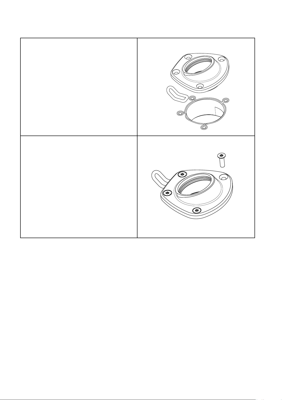
4.2 Fitting the drive unit
1.
Insert the drive unit from below

13
2.
Make sure the brackets fully mate with the
mounting surfaces in the deck and that there is
no interference between the drive unit and the
deck. Adjust if necessary. Check that the top
surface of the drive unit is slightly higher than
the top surface of the deck collar. (A)
3.
Mark out the positions for the 4 bracket screws
with a pen.
4.
Remove the drive unit. Drill and tap the four
holes M8 or 5/16. 20 mm full thread min (drill
depth ~25 mm)
5.
Test t the drive unit with all four screws.
Do not tighten fully. Remove the drive unit.
A
14
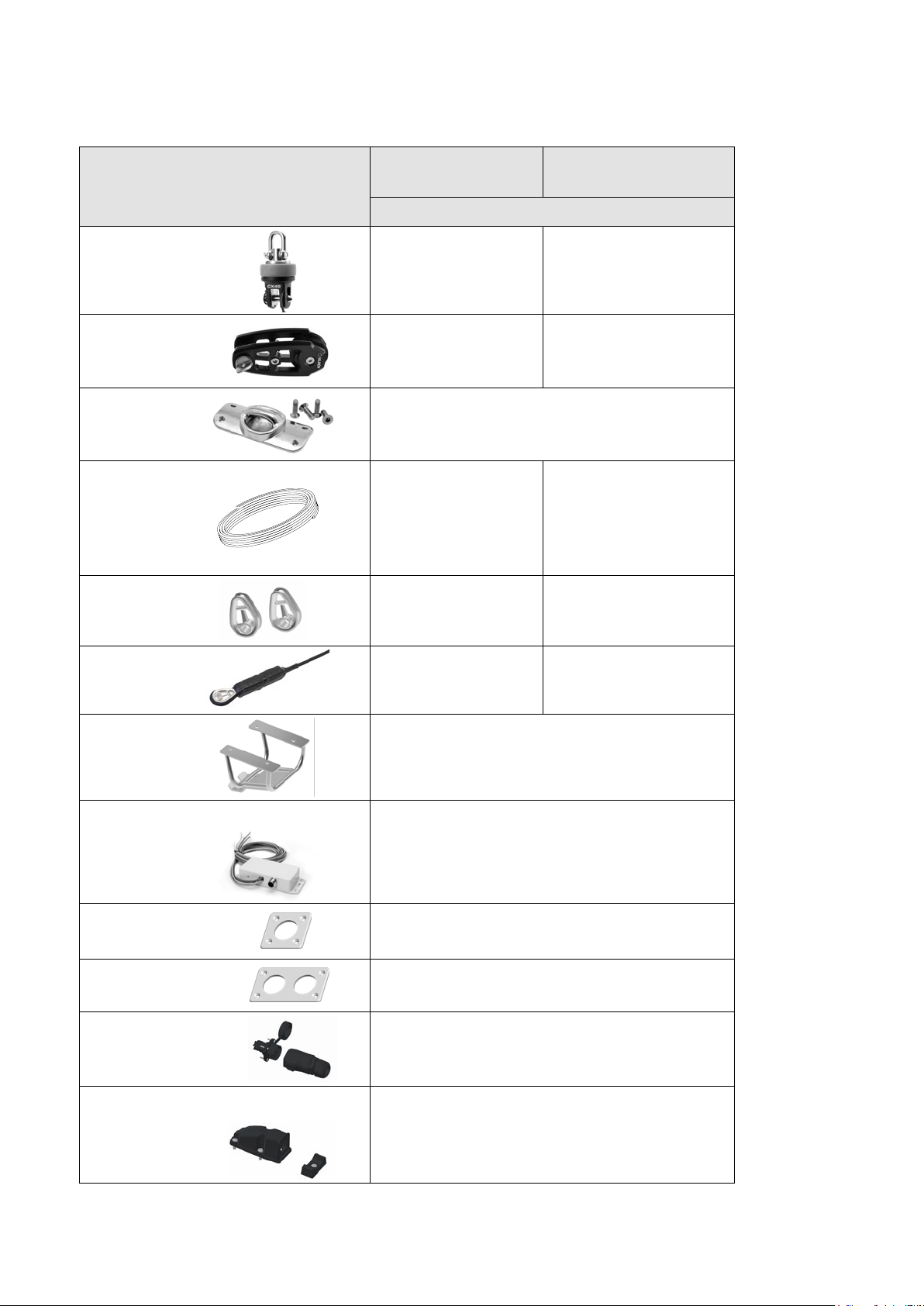
4.3 Assembly of the collar
1.
Remove the deck collar. Clean the deck and
mating surface of the deck collar with solvent.
Apply caulking around center hole and screw
holes. Also apply caulking to loop and t it in the
recess in the deck collar.
2.
Fit the collar, loop and screws. Using caulking
or other compound under the screw heads will
prevent corrosion.
Wipe o any excess.

15
4.4 Assembly of the drive unit
1.
Fit the two O-rings in the grooves in the deck
collar.
Apply a thin layer of grease on the O-rings.
2.
Insert the drive unit carefully making sure the
O-rings are not dislocated.
3.
Fit and tighten the screws. Use locking adhesive

16
5. Drive unit installation CXe TD through bow
sprit.
This chapter covers installation in stainless bow sprits or other metal designs
5.1 Assembly preparations
Always use protective goggles, gloves, dust mask and ear protection when working with metal.
Space requirements
-Check so that there is enough space for the installation. The dimensions are given in the section
”2.4 Technical Specication”.
-Note that the design needs to have a thickness of 44-48 mm at the two brackets.
-Weld nuts can replace tapped holes.
-The drive unit has a built in angle of 73°. Angle between AT-cable and bow sprit must be 73°+-2°.
Make a simple template and use halyard to check angle. Adjust surface under deck collar if necessary.
-Always use the deck collar and bracket insulators to prevent corrosion when drive unit is tted
in metal designs.
Strength of the bow sprit.
Make sure the bow sprit and area around drive unit can handle the load.
Max service load (MSL): CXe25: 25kN, CXe45: 45kN.
Tools required:
-Tape measure.
-Fine marking pen.
-Cloth tape.
- Hole saw or other suitable tool for making the ø88mm hole.
-ø3-4 mm drill bit for pilot holes.
-ø6.8 mm drill bit for M8 or drill bit for 5/16 thread if imperial screws are used.
-4x countersunk screws 5/16” in A4/316L quality. Length 1”.
-4x socket head cap screws 5/16” in A4/316L quality. Length 1 3/16”
All necessary screws (M8) are included in the kit.
-Set of Torx and Hex bits.
-Files-half round and round
-Marine type grease
-Corrosion inhibiting compound (grease can be used)

17
1.
Find the centerline of the bowsprit and mark out
the position of the ø88 mm hole.
Drill a ø4-5 mm pilot hole through center.
2.
Use hole saw or jig saw to make the center hole.
Take caution when using a jig saw not making
the hole too large.
3.
Adjust the distance between deck and mounting
surfaces.
Note that the dimension varies
depending on if the protective cage
is to be used or not.
44 mm thickness with protective cage.

18
1.
Fit the insulator to the deck collar and mount it
in the hole.
Adjust the hole for if necessary. Fit should be
as tight as possible.
2.
Align the deck collar and mark out the four
screw holes using the deck collar as template.
Remove the deck collar.
Drill and tap the four screw holes M8 or 5/16.
Test t the deck collar. Do not tighten screws
fully.
6 Installation
6.1 Fitting the deck collar
6.2 Fitting the drive unit
1.
Insert the drive unit from below
2.
Make sure the brackets fully mate with the
mounting surfaces in the bow sprit and that
there is no interference. Adjust if necessary.
Check that the top surface of the drive unit is
slightly higher than the top surface of the deck
collar. (A)
A
19
3.
Mark out the positions for the 4 bracket screws
with a pen.
4.
Remove the drive unit. Drill and tap the four
holes M8 or 5/16.
Drill clearance holes if nuts are used.
5.
Test t the drive unit with all four screws.
Do not tighten fully. Remove the drive unit.
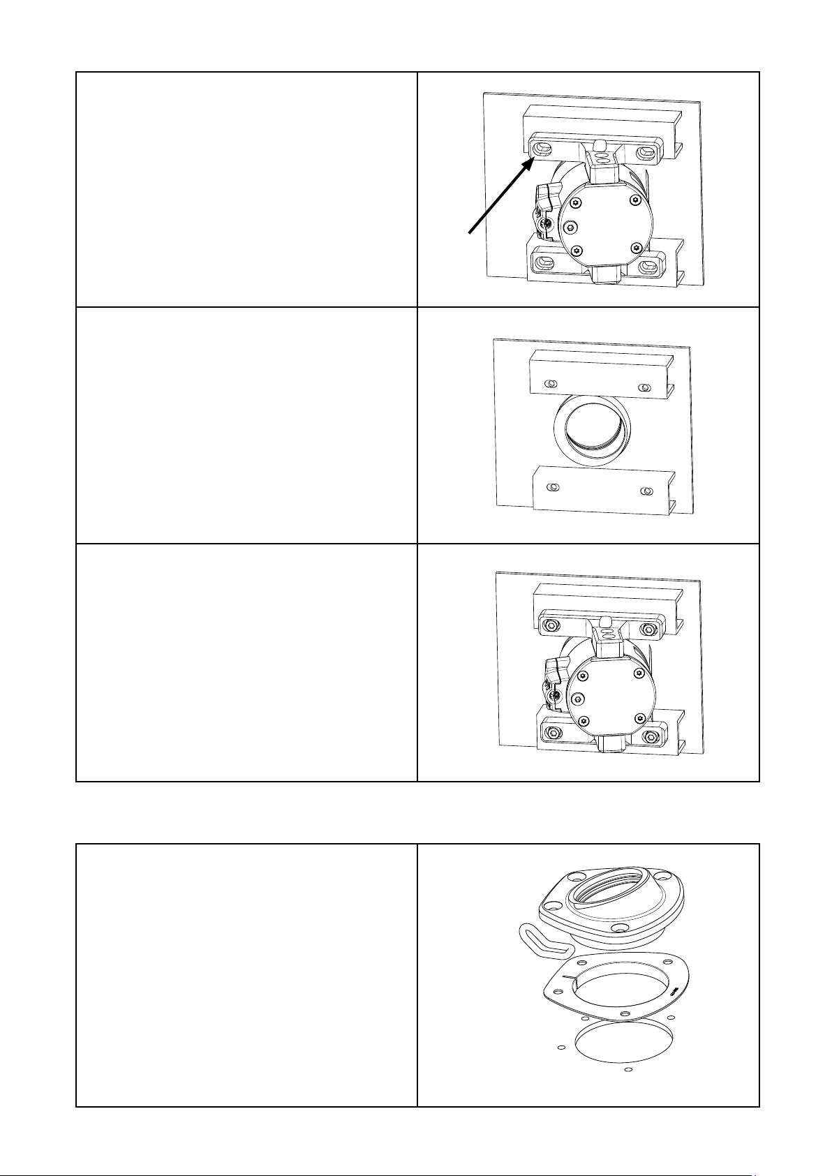
6.3 Assembly of the deck collar
1.
Remove the deck collar and insulator.
Apply caulking to the loop and t it in the recess
in the deck collar. Apply corrosion inhibiting
compound to mating surfaces.
20
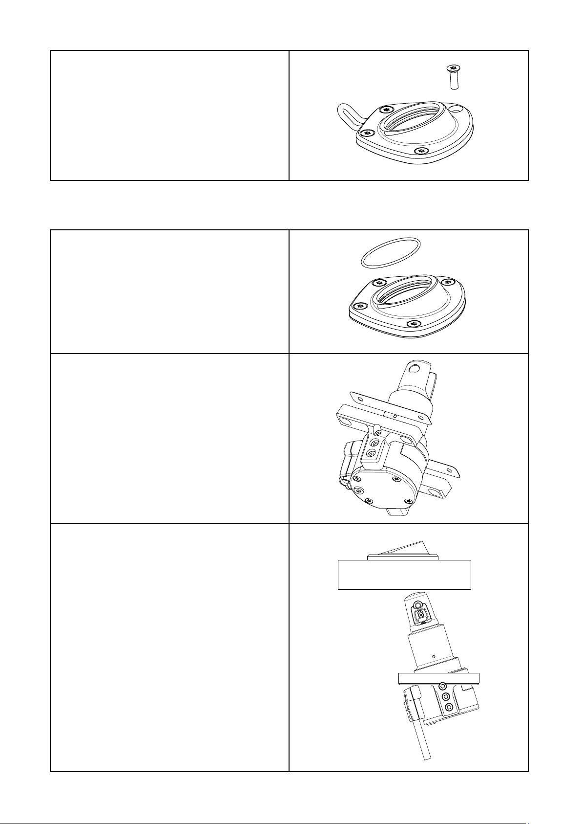
1.
Fit the two O-rings in the deck collar.
Apply a thin layer of grease on the O-rings.
2.
Fit the bracket insulators. Apply corrosion
inhibiting compound to mating surfaces.
3.
Insert the drive unit carefully making sure
the O-rings are not dislocated.
2.
Re-t the parts and t the screws. Use locking
adhesive.
Using caulking, grease or other compound
under the screw heads will prevent corrosion.
6.4 Assembly of the drive unit
This manual suits for next models
3
Table of contents
Other Selden Boating Equipment manuals

Selden
Selden SMF RC Guide

Selden
Selden Rodkicker 05 User manual

Selden
Selden 597-081-EF Owner's manual

Selden
Selden Furlex 500 H Series Instructions and recipes

Selden
Selden RB User manual

Selden
Selden 507-309-01 User manual

Selden
Selden Single Line Reef User manual

Selden
Selden 22 User manual

Selden
Selden Furlex 404E Instructions and recipes

Selden
Selden Furlex 50 S User manual


