Bennett H35 Series User manual

H35 Series Operation Manual
Operation Manual
High Flow H35 Hydrogen Series
Dual Cabinet Configuration
154807 Rev. B, 12.20.2023

H35 Series Operation Manual i
READ THIS MANUAL
Only Trained Personnel May Work on This Equipment
This manual contains important information for the safe operation of this equipment. Read and
understand this manual before applying power. All service personnel should read this manual prior to
performing service activities. The material included in this installation manual is accurate at the date of
publication. Failure to follow these instructions can cause bodily injury, damage to the equipment, or
death.
NOTE:Inspect shipped materials for damage or missing equipment. Bennett Pump Company is not
liable for the hazards of transportation. Please address damage claims directly to the delivery company.
NOTE: This device complies with part 15 of the FCC rules. Operation is subject to the following two
conditions: (1) This device may not cause harmful interference, and (2) this device must accept
interference received, including interference that may cause undesired operation.
NOTE: Not all equipment covered in this manual is listed by Underwriters Laboratories.
REV LEVEL DATE DESCRIPTION
A
11/22/2023
Release
B 12/20/2023 Revised Safety Instructions. Revised Error Code Table. 6.3 Safety Device Fault
Response created. Updated all section and figure references.

H35 Series Operation Manual ii
1SAFETY INSTRUCTIONS .......................................1
1.1 SAFETY MESSAGES ...........................................1
2OVERVIEW AND FEATURES.................................3
2.1 EXTERIOR LAYOUT ............................................3
2.2 ELECTRONICS UNIT INTERIOR DOOR LAYOUT.........4
2.3 MANAGER’S KEYPAD.........................................5
2.4 POWER SWITCH ...............................................5
2.5 MAIN DISPLAY REED SWITCHES ..........................6
2.6 ELECTRO-MECHANICAL TOTALIZER -OPTIONAL......7
3HOW TO OPERATE ..............................................8
3.1 DISPENSING FUEL .............................................8
3.2 ERROR MESSAGES ..........................................10
3.3 AC OFF MESSAGE .........................................11
4SETUP AND PROGRAMMING ............................12
4.1 BATTERY DISCONNECT BUTTON ........................13
4.2 DEFAULT SETTINGS .........................................13
4.3 INITIAL SETUP SEQUENCE.................................14
4.4 DISPENSER DISPLAY ........................................15
4.5 MANAGER’S KEYPAD OPERATION......................16
4.6 MANAGER’S ACCESS .......................................17
4.7 SELECT THE DISPENSER DISPLAY TYPE .................17
4.8 MENU CODE 0: DIAGNOSTICS ..........................18
4.9 MENU CODE 1: HOSE TOTALS ..........................18
4.10 MENU CODE 2: TOTALIZER TOTALS ...................19
4.11 MENU CODE 3: MANAGER’S ACCESS .................20
4.12 MENU CODE 4: PRICING..................................21
4.13 MENU CODE 5: TOTALIZER VALUE.....................22
4.14 MENU CODE 6: SPEED PROGRAMMING..............23
4.15 MENU CODE 7: DISPENSER TYPE.......................24
4.16 MENU CODE 8: DECIMAL LOCATION ..................26
4.17 MENU CODE 9: NO FLOW TIMEOUT ..................27
4.18 MENU CODE 11: MASS ALLOCATION.................28
4.19 MENU CODE 12: PRE-CHARGE TIME .................28
4.20 MENU CODE 13: BEEPER.................................30
4.21 MENU CODE 14: PPM DISPLAY OPTIONS ..........31
4.22 MENU CODE 15: FLEET OPTION .......................33
4.23 MENU CODE 16: PUMP HANDLE INPUTS ............34
4.24 MENU CODE 18: MONEY TOTALS .....................35
4.25 MENU CODE 21: COMMUNICATION TYPE...........36
4.26 MENU CODE 22: DISPENSER ADDRESS,PLC, PLC
LOWEST........................................................37
4.27 MENU CODE 26: SHIFT TOTALS ........................40
4.28 MENU CODE 27: ELECTRONIC CALIBRATION........43
4.29 MENU CODE 28: ROUNDING............................45
4.30 MENU CODE 29: RESETTABLE TOTALS ...............46
4.31 MENU CODE 30: REAL TIME CLOCK ..................47
4.32 MENU CODE 49: SOFTWARE REBOOT ................48
4.33 MENU CODE 50: PULSE OUTPUT ......................49
4.34 MENU CODE 51: NOZZLE DRYER CONFIGURATION
AND TIMING..................................................51
4.35 MENU CODE 66: NOZZLE TIME OUT..................52
4.36 MENU CODE 80: NOZZLE DRYER VALVE TEST ......53
4.37 MENU CODE 94: WEIGHTS AND MEASURES
TIMEOUT DELAY.............................................54
4.38 MENU CODE 99: VIEW E-CAL .........................55
5DIAGNOSTICS ................................................... 56
5.1 DIAGNOSTIC CODE 0.......................................56
5.2 DIAGNOSTIC CODE 1: DISPLAY SEGMENT TEST.....58
5.3 DIAGNOSTIC CODE 2: ERROR HISTORY ...............58
5.4 DIAGNOSTIC CODE 3: CPU TEST .......................59
5.5 DIAGNOSTIC CODE 4: FAULT HISTORY ................59
5.6 DIAGNOSTIC CODE 5: PUMP HANDLE TEST .........59
5.7 DIAGNOSTIC CODE 6: NOT USED.......................60
5.8 DIAGNOSTIC CODE 7: PRODUCT SELECT,KEYPAD
TEST ............................................................60
5.9 DIAGNOSTIC CODE 8: LAST SALE LIMIT ...............60
5.10 DIAGNOSTIC CODE 9: NOT USED.......................61
5.11 ERROR CODES................................................62
6APPENDIX ........................................................ 64
6.1 DISPENSER IDENTIFICATION NUMBER (DIN)........64
6.2 PULSE OUTPUT ..............................................65
6.3 SAFETY DEVICE FAULT RESPONSE ......................68
TABLE OF CONTENTS

Safety Instructions
H35 Series Operation Manual Back to TOC 1
1SAFETY INSTRUCTIONS
Please read and understand the following grouped safety messages that contain safety symbols and
safety words. They are defined as:
RED AND WHITE.IF YOU DO NOT FOLLOW THE INSTRUCTIONS, SEVERE INJURY OR DEATH WILL
OCCUR.
Orange and black. If you do not follow the instructions, severe injury or death can occur.
Yellow and Black. If you do not follow the instructions, damage can occur to the dispenser.
White italic NOTICE over blue. Indicates important information that should be observed.
1.1 SAFETY MESSAGES
1. DANGER: HYDROGEN IS FLAMMABLE. NO SMOKING OR OPEN FLAME.
2. DANGER: ALWAYS PLACE A PHYSICAL BARRIER AROUND THE WORK AREA BEFORE
PERFORMING SERVICE OR MAINTENANCE.
3. DANGER: DISCONNECT ALL POWER TO THIS EQUIPMENT DURING INSTALLATION, SERVICE,
OR ANY MAINTENANCE.
1. WARNING: To prevent electric shock, keep the electrical parts of the dispenser dry.
2. WARNING: Electronic components are static sensitive. Use proper static precautions (static
straps) before working on the equipment.
3. WARNING: Only technicians who have been trained in operation and programming of this
dispenser should perform programming and maintenance.

Overview and Features
H35 Series Operation Manual Back to TOC 3
2OVERVIEW AND FEATURES
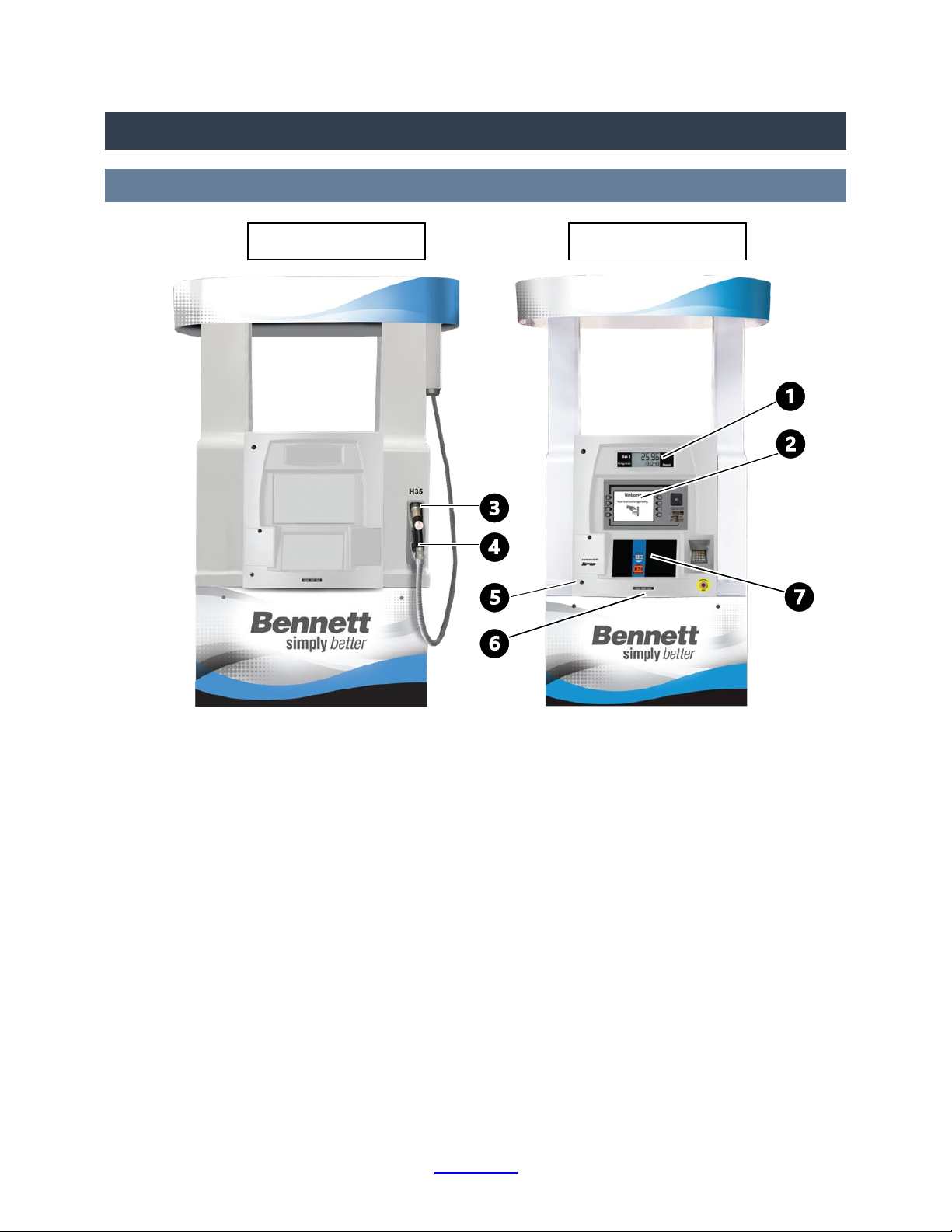
2.1 EXTERIOR LAYOUT
1. Main Display
2. Payment Panel Display (optional)
3. Nozzle Boot
4. Handle Switch
5. Locks (5 places each side each unit).
6. Electro-Mechanical Totalizer (optional)
7. Price Per Mass Displays (PPM) and
Product Select Buttons
Figure 1.1. H35 Dual Layout
Dispenser Unit
Electronics Unit
Overview and Features
H35 Series Operation Manual Back to TOC 4
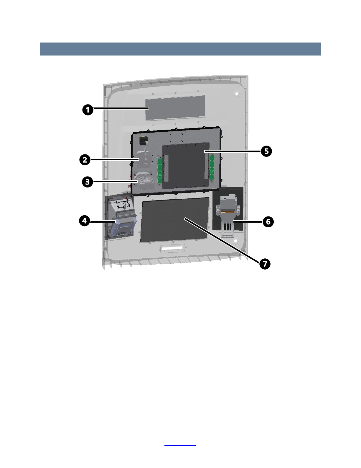
2.2 ELECTRONICS UNIT INTERIOR DOOR LAYOUT
1. Main Display Board
2. NFC Reader (optional)
3. Payment Card Reader (optional)
4. Keyboard (optional)
5. Payment Panel Display Board (optional)
6. Printer (optional)
7. Price Per Mass Board
Figure 1.2. Interior Door Layout

Overview and Features
H35 Series Operation Manual Back to TOC 5
2.3 MANAGER’S KEYPAD
•The Manager’s Keypad allows users to program and access data, see Figure 1.3.
•Various modes are available to configure and calibrate the dispenser for specific applications.
•The Manager’s Keypad connects to the PPM Circuit Board, refer to Section 4.5 Manager’s Keypad
Operation.
2.4 POWER SWITCH
4. WARNING: To prevent electric shock, make sure the circuit breaker(s) are OFF and locked
and tagged out before doing any repairs or maintenance to the dispenser.
The power switch on the 819 Power
Board turns the dispenser power ON and
OFF, see Figure 1.4. If the Power Board is
switched to OFF, the displays in the
dispenser remain illuminated for 30
seconds with power supplied by the 12-
volt battery.
Figure 1.3. Manager’s Keypad
Figure 1.4. 819 Power Board.
Top arrow - battery disconnect button.
Bottom arrow - ON/OFF switch.

Overview and Features
H35 Series Operation Manual Back to TOC 6
2.5 MAIN DISPLAY REED SWITCHES
The Reed Switches access electronic totals, the last sale, and audit trail
information. They are activated with the Access Magnet provided with the
dispenser, see Figure 1.5.
The reed switch locations are shown on Figure 1.6.
2.5.1 TOTALS SWITCH
To access totals:
1. Hold the Access Magnet over the location on Figure 1.6.
2. After a few seconds, “Prev” will be displayed on the
Price Per Mass (PPM) display.
3. Lift the magnet away.
4. The Main Display will show the previous sale amount
that occurred prior to the transaction that had appeared
on the display while idle.
5. To view the Totals, tap the magnet over the Totals Reed
Switch again. When the first money totals appear,
remove the magnet. The PPM display indicates the first
money total for product.
6. Tap the magnet over the Totals Reed Switch to view all totals from Mode 1 Hose Totals, Mode 2
Totalizer Totals, and Mode 26 Shift Totals.
Figure 1.5. Access Magnet
Battery Recall Reed Switch
Totals Recall Reed Switch
Figure 1.6. Magnet Reed Switch Locations.
Sale $
Kilograms

Overview and Features
H35 Series Operation Manual Back to TOC 7
To obtain Audit Trail information:
1. Hold the black Access Magnet over the Kilograms text (Totals Reed Switch) for a longer period of
time after the Totals Mode is displayed.
2. Once the data scrolls past the Totals Mode the Audit Trail information will appear. Lift and
return the magnet to cycle through:
2.5.2 LAST SALE RECALL SWITCH
The recall switch is behind the “SALE $” print. If dispenser AC power is OFF the recall switch connects the
displays to the battery and displays the last sale.
NOTE: If a pump handle is lifted and the dispenser is activated during this operation, the display returns
to idle.
To recall the last sale with battery power:
•Hold the Access Magnet over the “SALE $” print for approximately 2 seconds.
•The last sale in progress will display for 30 seconds.
2.6 ELECTRO-MECHANICAL TOTALIZER - OPTIONAL
The electro-mechanical totalizer displays cumulative totals in gallon or liter increments for each meter
and therefore each product being dispensed, see Figure 1.1. The totalizer is located below the product
select buttons on each side of the dispenser.
NOTE: Because of rounding methods used in electronic totals, over time electronic totals and electro-
mechanical totals will not match exactly.
Magnet Action Dispenser Display Audit Trail Sub-Menu Description
Touch magnet to Totals
Reed Switch
ECAL 1A, b, c
000001
E-Cal changes for Side 1 meters.
Lift away reengage ECAL 2A, b, c
000001
E-Cal changes for Side 2 meters.
Lift away reengage unitch
00000
Mass Unit Changes (gallons to liters to
imperial gallons).
Lift away reengage 4olrES
0000
Mass resolution changes (0.001 or
0.01).

How to Operate
H35 Series Operation Manual Back to TOC 8
3HOW TO OPERATE
NOTE: If the dispenser ends a sale early, verify that no error code is shown on the main display before
trying again. Refer to Section 5.11 Error Codes for more details.
NOTE: The dispenser must be authorized by the console or set to operate in stand-alone mode, see
Section 4.25 Menu Code 21: Communication Type.
3.1 DISPENSING FUEL
To activate the dispenser (Please also see Section 3.1.1 Fueling Steps):
1. Pay if necessary.
2. Lift the nozzle from the nozzle boot.
3. Attach nozzle to vehicle receptacle.
4. Lift the nozzle handle switch.
5. The dispenser will check for IR communication from vehicle.
a. If communications are established, the dispenser will automatically proceed to the next step.
b. If communications are not detected, the payment screen will instruct user to either abort or
continue without communication.
6. The payment screen will instruct user to press the grade select button.
7. The dispenser will proceed with fueling protocol to dispense hydrogen to the vehicle.
8. The payment screen will display a message to inform the user when fueling has been completed
and instruct them to replace the nozzle.

How to Operate
H35 Series Operation Manual Back to TOC 9
3.1.1 FUELING STEPS
Once authorized the dispenser will display the following fueling steps:
Timeout (15s) waiting for
vehicle communication.
Successful communication
with vehicle.
Pressed continue arrow.
Timeout waiting for nozzle
to be replaced.
Replaced nozzle.
*Displayed after PLC aborts sale, power failure
occurred during sale, or dispenser throws an error.
*Displayed after a dispenser throws an
error, or station or dispenser not ready for
sale.

How to Operate
H35 Series Operation Manual Back to TOC 10
3.2 ERROR MESSAGES
When an error message appears on the display, there is a fault condition in the dispenser. Two digits will
follow the error message to indicate the cause of the error. Refer to Section 5.11 Error Codes.
Recommended error message procedure:
1. Determine what caused the specific error.
2. Fix the issue.
3. Clear the error. To reset an error code, lift and lower the nozzle handle switch twice.

How to Operate
H35 Series Operation Manual Back to TOC 11
3.3 AC OFF MESSAGE
The AC OFF message will display during power interruption or disconnection. Depending on the display
configuration, the message will appear as shown in Figure 2.1.
If the power is OFF and the AC OFF message does not appear, the charge is low on the 12-volt battery.
Recharge or replace the battery. Failure to replace the battery could result in loss of dispenser electronic
totals and stand-alone operating data.
Figure 2.1. AC OFF Message
Sale $
Kilograms
AC
Off

Setup And Programming
H35 Series Operation Manual Back to TOC 12
4SETUP AND PROGRAMMING
Menu Codes are accessed with the Manager’s Keypad. Menu Codes 0, 1, and 2 are diagnostic error
codes or totals. To access menu codes 4 - 99, follow the keypad sequence in Section 4.6 Manager’s
Access. In the menu code table below, Access Types are:
•Keypad Access: Data can be directly entered
•Passcode Access: The passcode is required, see Section 4.6 Manager’s Access
•Cal Switch: Setting the calibration switch is required, see Section 4.28 Menu Code 27
Menu
Code
Name Access
Type
Description
0
Diagnostics
Keypad
Diagnostic Tests
1
Hose Totals
Keypad
Displays money, mass, amounts of sales, and price changes.
2
Totalizer Totals
Keypad
Displays electronic totalizer totals only.
3
Manager Access
Keypad
Enter a four-digit access code to enter codes 4 and higher.
4
Pricing
Passcode
Set price per mass for each hose and one- or two-tier pricing.
5
Totalizer Value
Passcode
Enter a value for each electronic totalizer (mass total).
6
Programming
Passcode
Review and program the most common code settings.
7
Dispenser Type
Passcode
Set the number of sides and number of grades.
8
Decimal Location
Passcode
Change decimal placement for other than U.S. standard.
9
No Flow Time Out
Passcode
Set a time for the dispenser to turn off after flow stops.
11
Mass Allocation
Passcode
Control maximum mass of a single sale at one pump.
13
Beeper
Passcode
Set beeper tone options.
14
Price Display
Passcode
Set the way price displays operate.
15
Fleet Option
Passcode
Set the fleet system interface compatibility.
18
Money Totals
Passcode
Set the money totals calculation method.
21
Communication Type
Passcode
Set the dispenser in stand-alone or console modes.
22
Dispenser Address
Passcode
Set the dispenser address.
26
Shift Totals
Passcode
Reset shift totals.
27
Electronic Calibration
Cal Switch
Electronically calibrate the dispenser.
28
Rounding
Passcode
Set the sale amount to round or truncate.
29
Resettable Totals
Passcode
Enter a value for each meter on the dispenser (mass total).
30
Real Time Clock
Passcode
Set current time and date.
49
RAM Clear
Passcode
Reboots the system and clears
50
Pulse Output Config.
Passcode
Pulse output simulates a mechanical dispenser interface.
51
Nozzle Dryer
Passcode
Program the length of nozzle drying time.
66
Nozzle Time
Passcode
Sets nozzle timeout.
80
Valve Test
Passcode
Test the solenoid valves in the upper cabinet.
94
WM Timeout
Passcode
Set the Weights and Measures Timeout delay regulations.
99
View E-CAL
Passcode
View meter calibration and mass adjustment values.

Setup And Programming
H35 Series Operation Manual Back to TOC 13
4.1 BATTERY DISCONNECT BUTTON
To turn OFF the battery power after switching OFF the main power, wait 5 seconds, then press and hold
the battery disconnect button until the display is blank, see Figure 1.5.
4.2 DEFAULT SETTINGS
The software program for each new dispenser shipped from the factory is preprogrammed with default
settings in some of the Menu Codes. Some menu codes must be changed immediately to make the
dispenser operational, refer to Section 4.3 Initial Setup Sequence. The default listings are noted below:
Menu
Code
Name Default
3
Manager Access
2218
7
Dispenser Type
2 = Sides, 3 = Grades
8
Decimal Location
1 = U.S.A.
9
No Flow Time Out
--- = Infinite Time
11
Mass Allocation
0999 Mass Units
12
Pre-Charge Time
2 seconds
13
Beeper
3 = Combination of option 1 and 2 (Audio Tones)
14
Price Display
1 = Flashing, 0 = Blanks
15
Fleet Option
1 = Enabled
18
Money Totals
0 = Cash Drawer method
21
Communication Type
0 = Console Mode
22
Dispenser Address
0 = Only one dispenser on the communications loop
28
Rounding
1 = Rounding the Sale Amount
80
Cycle Valves
0 = Off
99
Unit of Measure
1 = Kilograms, 1 – Decimal position 3 places
Setup And Programming
H35 Series Operation Manual Back to TOC 14
4.3 INITIAL SETUP SEQUENCE
To program the dispenser’s memory for the first time or following a RAM memory clear, follow the
menu codes in the order listed in the “Initial Setup Sequence” table below. Verify the menu codes are
programmed before testing any dispenser operations.
Initial Setup Sequence – Required Remaining Setup - Recommended
Menu
Code
Name Menu
Code
Name
3
Managers Access
5
Totalizer Value
7
Dispenser Type
8
Decimal Location
4
Pricing
12
Pre-Charge Time
9
No Flow Time Out
14
Price Display
11 Mass Allocation 15 Fleet Option
21
Communication Type
18
Money Totals
22
Dispenser Address
26
Shift Totals
28
Rounding
29
Resettable Totals
99
Unit of Measurement
30
Real Time Clock
Setup And Programming
H35 Series Operation Manual Back to TOC 15
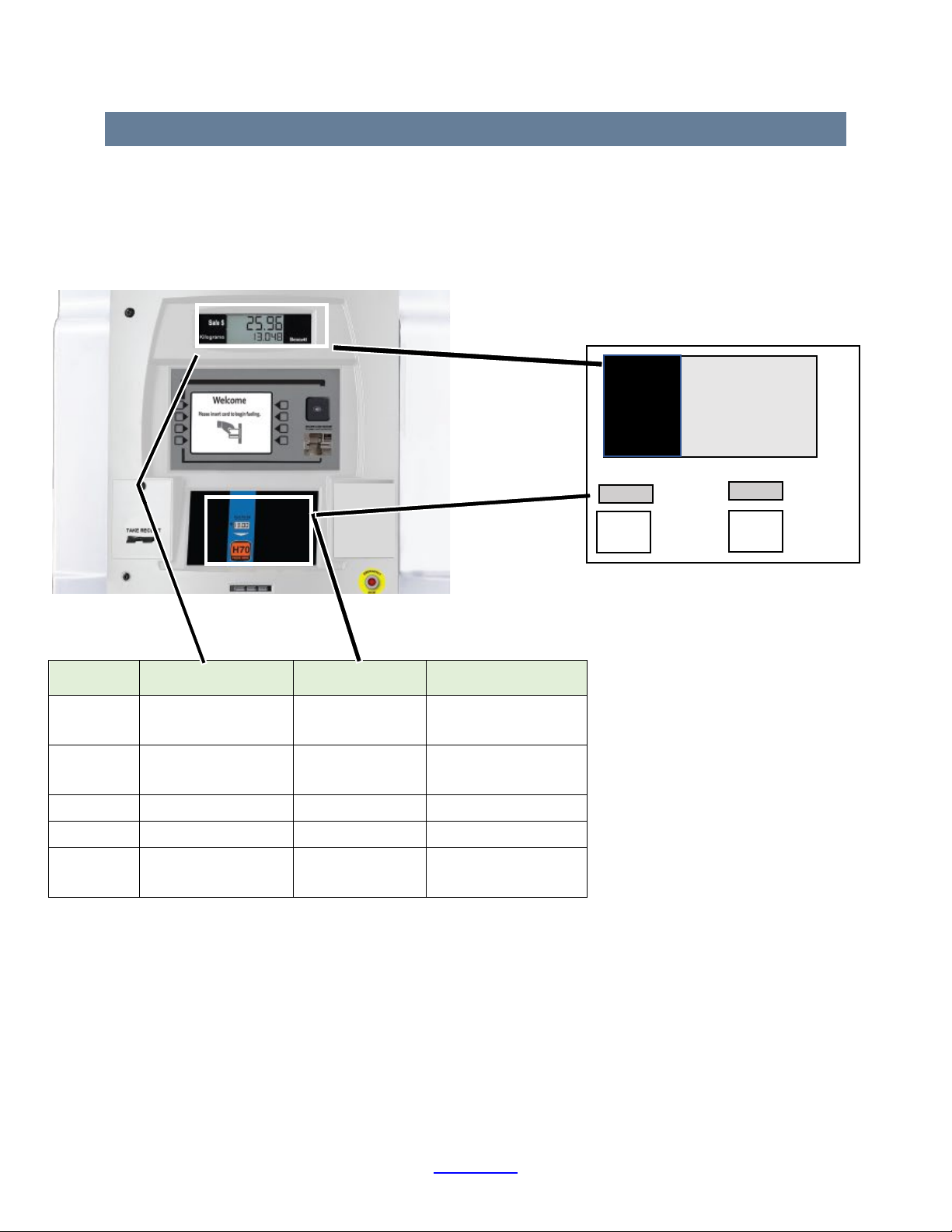
4.4 DISPENSER DISPLAY
This manual uses two methods to describe the dispenser displays and what they will show when using
the Manager’s Keypad to access menu codes or modes. One method is a graphic, shown below to the
right, and the second method is a table, below. The upper graphic Sale and Kilograms represent the
upper display. The lower part of the graphic represents the lower PPM display. The table headers
describe the columns representation.
Keypad
Action
Main Display Results
Lower PPM Display
Results
Description
Plug in the
Keypad
EntEr
SidE 1 PC4P Select desired
programming side.
Enter COdE
00 SidE 1 Managers Access Ready
3, Mode PASS CodE 3 Password Ready
2218, Enter PASS CodE - - 3 Password Accepted
Cancel COdE
00 SidE - - 1 Exit
COdE
00
--1
Sale $
Kilograms
sidE
Setup And Programming
H35 Series Operation Manual Back to TOC 16
4.5 MANAGER’S KEYPAD OPERATION
To enable the dispenser for setup and programming, follow this procedure:
1. Hang up all nozzles in their boots. If any nozzle is not hung up, the dispenser will beep and not
enter manager mode.
2. Unlock and open the upper door of side one. Side one has louvered doors at the top of the
dispenser on the outside. On the inside, side one has the serial number tag on the left side, at
eye level.
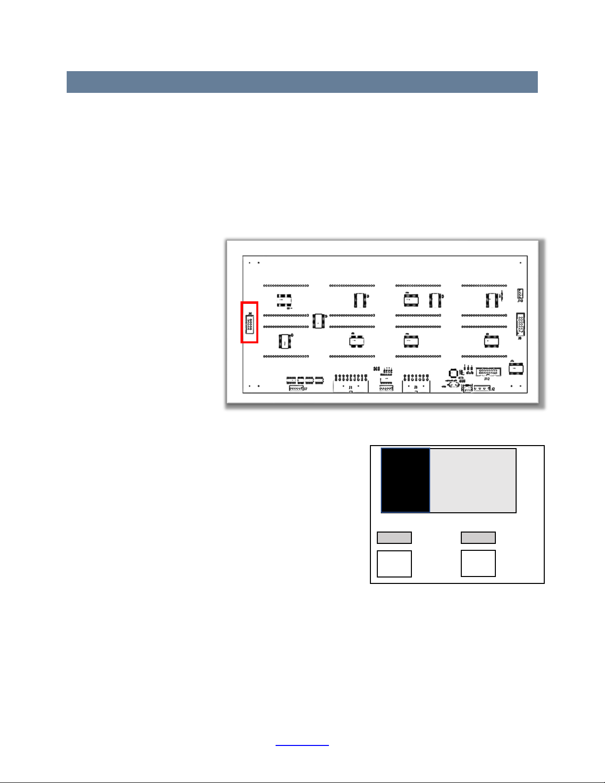
3. The keypad receptacle is located on the Price Per Mass Board (J4), which is located on the lower
back of the side one
door, see Figures 1.6.
See Figure 3.1. for
keypad receptacle
location.
NOTE: Connecting the keypad
to the side two P.P.V.
Display Board will not
provide access to Menu
Codes.
4. Plug the keypad into
the receptacle.
5. After connecting the
keypad, the dispenser
will automatically enter the managers programming
mode. “Enter side 1” will be on the dispenser’s side 1
display. The side 2 screen will display “OFFLINE”.
6. On the keypad, press Enter to access Manager’s Mode.
The display appears as shown in Figure 3.2.
7. See Section 4.6 Manager’s Access. To program a specific
Menu Code, refer to the Table of Contents for the page
location.
8. When the programming session is complete disconnect
the keypad from the receptacle, return to storage.
9. The dispenser will automatically enter the operating
mode.
Figure 3.2. Manager’s Mode
Figure 3.1. Keypad Receptacle (Red Rectangle) on the Price Per Mass Board.
Sale $
Kilograms
COdE
00
SidE
--1

Setup And Programming
H35 Series Operation Manual Back to TOC 17
4.6 MANAGER’S ACCESS
The following keypad sequence is necessary to get access to any code that is three (3) or higher:
Keypad
Action
Main Display Results
Lower PPM Display
Results
Description
Plug in the
Keypad
EntEr
SidE 1 PC4P Select desired
programming side.
Enter COdE
00 SidE 1 Managers Access Ready
3, Mode PASS CodE 3 Password Ready
2218, Enter PASS CodE - - 3 Password Accepted
Cancel COdE
00 SidE - - 1 Exit
Table key.
4.7 SELECT THE DISPENSER DISPLAY TYPE
Upon receiving a new dispenser, the display should be factory pre-programmed and working as
expected. If the 819 Control Board has been replaced or the memory has been erased, the main display
may show distorted text. In this case follow this procedure:
1. Plug in the Manager’s Keypad
2. Press +/-five times. Each five or so cycles will change the display.
3. Stop cycling when appears on the main display.
4. Confirm that the main display and the price displays show real numbers and real letters.
EntEr
SidE l
Other manuals for H35 Series
2
Table of contents
Other Bennett Marine Equipment manuals

Bennett
Bennett BOLT Rocker BRC4000 User manual

Bennett
Bennett BOLT Control BCI8000 User manual

Bennett
Bennett H35 Series User manual

Bennett
Bennett SITE MASTER EMV User manual

Bennett
Bennett LNG Series User manual

Bennett
Bennett 621 User manual

Bennett
Bennett H35 Series User manual

Bennett
Bennett HIGH FLOW H35 User manual


