PMG ULTRAGUARD Antifouling Master Series User manual

OWNER’S MANUAL

How Does Ultraguard Work
The microbiome and larvae that are the early stages of marine growth require a number of
environmental criteria to be in an optimum state to allow them to begin the colonisation
process. These criteria include water temperature, salinity, light levels, time of year,
concentration of larvae and seed in the water and many other criteria can affect colonisation
depending on the species and type of growth. A suitable substrate to attach to is also
essential.
Our goal is to use ultrasonic sound waves to create a resonance in the substrate which causes
a vibration in the surface of the substrate. This, in turn, becomes a sub-optimal location for
the colonisation process to begin. This vibration can only prevent the colonisation at the larval
stage. Mature growth creates bonds that are too strong to be affected by the vibrations. To
this end, ultrasonic antifouling systems can only keep a clean substrate clean, they cannot
clean a heavily fouled surface.
It sounds like a simple process but acoustically there are many challenges to overcome,
especially on acoustically complex structures such as coolers. It is the research and
development that MGPS and our partners have undertaken that sets Ultraguard apart from
the competition.
Each transducer acts like an audio speaker. In the control panel, each transducer has its own
control board and power supply. These generate ultrasonic acoustic signals which are then
boosted via an amplifier and sent down the cable to the transducer. The transducer is
attached to the structure being protected by an adhesive bond. It is essential that there is
always full surface to surface contact between the transducer head and the protected
structure. This is why we choose the bonding method over methods such as a screw in ring
welded or attached to the surface. In that method the ultrasonic waves can loosen the
transducer in the mounting ring.
By causing each transducer to resonate at the correct frequency we induce the required
vibrations which prevent the larvae from attaching themselves to the surface being
protected.
Ultraguard’s design means that if a transducer cable, power supply or control PCB is damaged
or fails it can be swapped out by ship’s staff in a matter of minutes. The rest of the system
can operate as normal until the replacement takes place so there is minimum downtime and
minimum loss of antifouling effect.

The Birth of the Master Series
Ultraguard Antifouling from Marine Growth
Prevention Specialists Ltd (MGPS) is the World’s
premier ultrasonic antifouling system, providing
environmentally friendly and cost effective antifouling
solutions to the commercial marine industry.
Based on MGPS’s years of experience in the
commercial maritime industry, Ultraguard Antifouling
was designed from the start with the unique
challenges of the shipping world in mind. The UG
series of antifouling systems has fast become the go
to alternative to high cost and highly polluting legacy
antifouling techniques.
Ultraguard was approached by some customers who operated smaller commercial craft such as
workboats and crew boats which had the same problems with marine growth as bigger commercial
vessels, but which did not have onboard generators and the AC power requirements needed for the
UG Series systems, nor did they have the space to fit large electrical enclosures aboard their vessels.
They had looked at offerings from other manufacturers but felt that they were older technology, had
lower power outputs and were not really robust enough for the commercial market.
The challenge had been set and we grasped it with
both hands. Could we get the same powerful
commercial grade antifouling system into a package
which would allow smaller commercial craft and
leisure boat owners to enjoy the benefits of
Ultraguard?
Our best minds on both the electronics and enclosure
aspects got straight to the job in hand and within a few
months, Ultraguard Master Series was born!

The Birth of the Master Series
The Master Series units have exactly the same signal
generation, control and amplifier circuits onboard as the
full UG commercial series from Ultraguard does. The
Master Series has the same powerful acoustic output
and creates the same antifouling effect that major
shipping companies all over the world already enjoy
from Ultraguard.
The only difference electronically is that we were able to leave out the power supply that converts AC
power to DC and replace it with a PCB designed and built by our team which manages the incoming
DC power, smooths it out and adds a safety device between the system and the supply from the vessel’s
batteries. This is important as the amplifier transformers hold current in their coils and this needs to be
prevented from damaging the batteries (During our research we were shocked to see that some
competitors don’t have this!).
Packaged into a custom designed and robust aluminium
enclosure, the Master Series is the perfect solution for tackling
marine growth on small commercial and leisure craft!
The Ultraguard Master Series systems are designed, developed and
manufactured in the United Kingdom, mostly in the Silicon Glen of
central Scotland.


120w / 20kHz Ultraguard Transducer (x 2) 10m Transducer Cable (x2)
12v DC Power Cable 24v DC Power Cable
Loctite HY 4070 Transducer Adhesive

Fitting the Control Unit
Locate a suitable location for the Ultraguard Master Series control unit. It should be a dry area, inside
and protected from the elements. Ultraguard recommends that you fit the control unit as close as
possible to your power source in an area which is easily accessible. The control unit has four adjustable
mounting brackets. Simply attach the unit to a secure bulkhead or panel using fixings (Not Supplied)
through the slots on the brackets.
Power Connection
The Ultraguard Master Series control unit can run on either a 12v DC or 24v DC power supply. There
are two power cables included in your kit, one for 12v DC and the other for 24v DC. Simply choose the
correct cable for your supply voltage and connect it to the power cable connection on the control unit.
(DOUBLE CHECK YOU HAVE THE CORRECT CABLE; THEY ARE NOT INTERCHANGEABLE)
This connector can only fit together one way. Line up the locating tab with its corresponding slot.
Push the cable end connector and control unit connection socket together and screw up hand tight.
The power cable ends have been left unterminated to allow each customer to terminate in the best
manner for their vessel. We recommend using crimp-on connectors of suitable amperage rating (See
technical specification page) that best connects to your onboard power supply. Non insulated crimp-on
connectors should be insulated with heat shrink tubing after fitting to the cable ends.

Fitting the Transducers
Before installing your Ultraguard transducers, plan out where the best location is for each transducer.
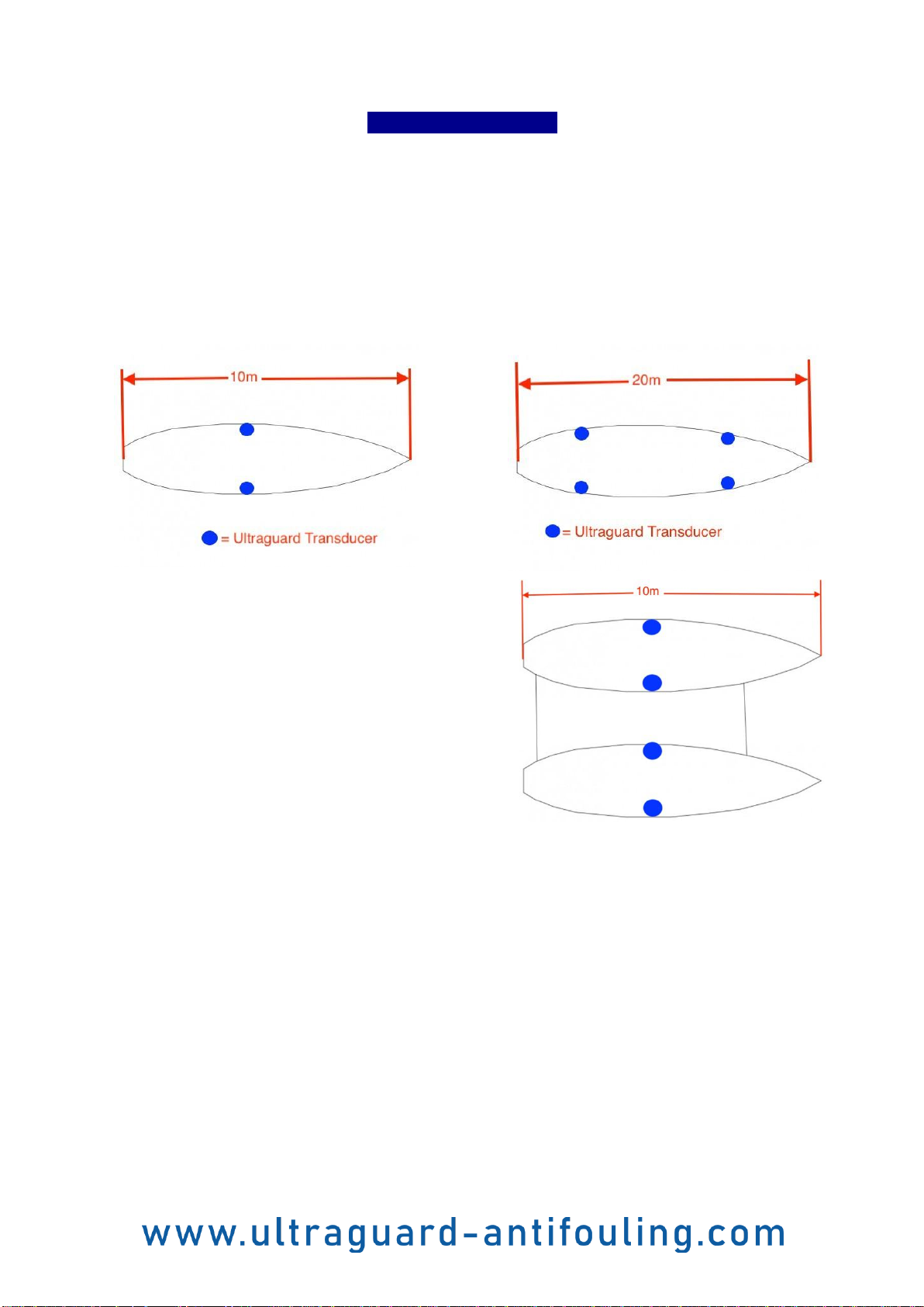
Transducers should be located directly onto the inside (dry side) of the hull’s outer shell. Each
transducer has an effective antifouling radius of five metres on uninterrupted surfaces. Acute angles
and reinforcements can reduce the transmission of the sound waves. For this reason, we recommend
locating transducers in pairs, one on each side of the vessel to ensure that the antifouling effect is not
lessened by the acoustic waves having to pass through the keel of the vessel. Each Ultraguard Master
Series control unit can operate two transducers. If your vessel’s underwater area is longer than ten
metres, you will need to add additional Ultraguard Master Series control panels to protect the entire
length of the underwater hull. For larger vessels and ships, Ultraguard’s AC powered commercial UG
series systems may be more suitable.
If your boat is a multi-hull vessel, you should treat each
hull sponson as an individual hull.
It is best to locate transducers as close as possible to
the halfway point between the waterline and the
moulded keel (not including attached keels, drop keels,
dagger boards etc).
Ideally, we recommend locating transducers away from
any framing there may be on the vessel. The object is to
set up a microvibratory response in the shell off the hull
and this is better achieved by locating the transducer as
equidistant as possible between frames, stringers and
bulkheads.
If your vessel’s hull has a sandwich laminate construction with a foam, plywood or honeycomb core
between an inner and outer skin of GRP/Carbon fibre/Kevlar, then a disk slightly larger than the
transducer head will need to be cut out of the inner skin and the sandwich core. This cut-out should
then be filled with solid resin/fibre laminates ensuring that there are no air gaps created to build a base
for the transducer that allows the transducer to transmit the acoustic waves directly to the outer shell of
the hull.
If the inner surface of your hull has a rough GRP finish that can’t be sanded smooth it may be necessary
to apply a skim of resin to the transducer locations before fitting the transducers. This is done to avoid
air gaps between the transducer head and the hull. This is extremely important as air gaps that are
subjected to powerful ultrasonic waves can cause erosion of the surface.

Fitting the Transducers to the Structure
1. Mark around the transducer with a marker pen. 2. Clean substrate to bare, flat, smooth and paint free
3. Soak clean lint free cloth in acetone or similar. 4. Thoroughly clean substrate until surgically clean
5.
Repeat cleaning process on transducer head. 6. Make a serpentine trail of adhesive across the transducer
head and smear to smooth even coating with a spatula
7. Immediately set transducer into location 8. Press firmly on transducer for 20-30 seconds to set bond.

Fitting the Transducers to the Structure
Locate where you want to fit the transducers using the guide in these instructions. On hulls you should
locate the transducers as equidistant from hull frames as you can to allow the maximum resonance
response.
Draw around the transducer with a marker pen so as toeasily see the area you need to prepare.
Remove the paint and any coatings right back to the bare substrate.
Ensure the surface is smooth and free of gouges or dimples that could cause an air gap
between the transducer and the surface.
Clean the surface and the head of the transducer with acetone or similar solvent until both
surfaces are, ‘Surgically,” Clean. (Unfortunately, Ultraguard cannot supply acetone due to
carriage difficulties)
Once the surfaces are clean DO NOT TOUCH them again with fingers or skin as the oils in
your skin affect the bond. If you do, re-clean thoroughly.
Ensure you are happy with the location and practice dry fitting the transducer.
Once you are happy with location, get into position to apply the transducer. The adhesive will
cure in seconds and you have to place the transducer onto the surface IMMEDIATELY once
the adhesive is applied. (You will not have time to move from a work bench or other location
before the adhesive cures!)
Fit the supplied nozzle to the adhesive syringe
Have a spatula or similar implement ready to spread and smooth adhesive.
Apply a serpentine bead across the face of the transducer and immediately smooth it across
the transducer face with the spatula. The aim is to have an even coverage of 2mm-3mm thick
with no bare spots which could form air gaps (The threaded hole does not need to be filled, this
is for use with adapters if protecting pipes).
IMMEDIATELY place the transducer into location and hold in place for 30 seconds.
Leave the transducer to fully cure for 24 hours before connecting its cable to the control unit.
Whilst waiting you can run the main section of transducer cable back to the control unit.
Ultraguard recommends using suitable cable trays and conduits to achieve this.
If using an Ultraguard Pipe Adapter (Available separately), attach the adapter to the pipe first
in the same manner as above then repeat the process to attach the transducer to the adapter
using the M10 x 1mm threaded stud to locate the transducer correctly.

Starting the System and Fault Finding
Wait at least 24 hours after bonding the transducers to allow a full cure of the adhesive to take place
before plugging the transducers into the control unit.
When switching on the control unit, it is normal for the Transducer Operation LEDs on the end plate of
the control unit to remain blank for a few seconds whilst the control circuit initializes and pulse width
modulation (PWM) begins. The LEDs should then turn GREEN and remain so throughout operation.
Blank LEDs during Initialization Two Green LEDs during Normal Operation
Amber LED at Switch On
If the LEDs turn AMBER, check that the transducer
cable is properly connected to the panel and that
there is no damage to the cable.
Blank LEDs at Switch On
If the LEDs do not illuminate and remain blank, check
that power is properly applied to the panel and that
the power switch is in correct position. If it is contact
Ultraguard Antifouling for further assistance.

Starting the System and Fault Finding
Red LED at Switch On
There is a major PCB Fault. Contact Ultraguard
technical support.
Amber LED during Operation
There is a minor fault on the system. Switch off circuit.
Check transducer cable is properly connected and that
the cable is not damaged or broken along its length.
Switch circuit back on, fault should have cleared. If fault
re-appears contact Ultraguard technical support.
Red LED During Operation
System has a major fault. Switch off circuit, wait 30
seconds and switch the circuit back on. Fault should
clear. If fault re-appears please contact Ultraguard
technical support.

Warranty
All Ultraguard Master Series systems have a two year warranty from purchase against defects or
component failure.
We ask that all owners register their system for warranty at:
https://ultraguard-antifouling.com/register-warranty
Please contact Ultraguard via the email addresses on the inside front cover of this manual or via our
website:
www.parkermarinegroup.co.nz
Spare Parts
All components are available as spare parts from Ultraguard Antifouling. Please contact our sales team
to discuss your requirements whether that be for repair out with warranty or to maintain a spares kit
aboard the vessel for quick repairs at sea.
Extra Parts
If you require extra parts such aspipe adapters or transducer cable extensions, please
contact our sales team.
Transducer Cable Extensions
Ultraguard Pipe Adapters

Technical Specifications
Control Unit Dimensions: L = 260mm x H = 200 (including brackets) x D = 52mm
Control Unit Weight: 1600g
Power Cable Length: 1250mm
Transducer Dimensions: Ø = 90mm x H = 105mm
Transducer Weight: 1450g
Transducer Cable Extension Length: 10m
Control Unit Current Draw (Two Transducers Attached): @12v DC –Inrush = 11 Amps
Continuous = 1.1 Amps
@24v DC –Inrush = 6 Amps
Continuous = 0.55 Amps
Power Consumption (Two transducers operating): 13.2 Watts Continuous
Transducer Power: 120w
Frequency Range: 18kHz –42kHz
Control System: Fully digital microprocessor controlled signal generator and amplifier circuits
Place of Manufacture: Fife, Scotland, United Kingdom
Installation, maintenance and repairs of Ultraguard Antifouling systems
should ONLY be carried out by competent personnel who are familiar with
marine electrical systems!
There is a risk of severe injury or death when working in the vicinity of live
electrical equipment. ALWAYS ensure proper isolation and safety lock
out procedures are followed!

Parker Marine Group
36 Brett's Place,
Kauri,
Whangarei 0185
Phone: 0275504140 or 09 4377051
Email: info@nzmarinedistribution.co.nz
Other PMG Marine Equipment manuals
Popular Marine Equipment manuals by other brands

Speedtech
Speedtech DEPTHMATE SM-5A Operation manual

Edgetech
Edgetech 6205S2 USER HARDWARE MANUAL

AML Oceanographic
AML Oceanographic AML-1 RT user manual

DIGITAL YACHT
DIGITAL YACHT Fusion 700 Series Technical notes

CanDock
CanDock G2 JETSLIDE Installation and use

Clarion
Clarion CMS20 Owner's manual & installation manual